Tenor AX
VoIP MultiPath/Gateway
Switch
Product Guide
P/N 480-0062-00-13
Tenor and Quintum are registered trademarks. PacketSaver, Quintum Technologies, Inc., Risk Free VoIP, VoIP Made Easy, SelectNet, and SelectNet Technology are trademarks of Quintum Technologies, Inc.
This unit contains new hardware, which requires newer software. This software was installed on the unit prior to leaving the factory.
If you must downgrade the software in this unit, please visit http://ae.quintum.com/support/ rohs/ for a list of latest software patches that support this new hardware. Loading unsup-ported software will render this unit inoperable and will require physical access to this unit for recovery.
T
able of Contents
About this Guide
What’s included? . . . 1-2 Typographical Conventions . . . 1-3 Product Guide Conventions . . . 1-3 Finding Help/More Information . . . 1-4 Chapter 1: Overview
What is the Tenor AX?. . . 1-2 Features. . . 1-4 Unique Design . . . 1-4 State-of-the-Art GUI Configuration and Network Management . . . 1-4 Easy Connect to Console . . . 1-4 Powerful System Monitoring . . . 1-4 Capabilities . . . 1-5 SelectNet™ Technology Safety Net (for Tenor AXM and Tenor AXE configurations). 1-5 PacketSaver™ reduces bandwidth consumption . . . 1-5 Virtual Tie Trunk. . . 1-5 SNMP Support . . . 1-6 Call Detail Recording . . . 1-6 IVR/RADIUS Support . . . 1-6 NATAccess™. . . 1-6 Dynamic Call Routing . . . 1-7 Tenor AX Call Paths . . . 1-8 Tenor AXM MultiPath Switch (AXM800, AXM1600, AXM2400) Configuration . . . 1-8 Tenor AXT Trunking VoIP Gateway (AXT800, AXT1600, AXT2400, AXT4800)
Configuration . . . 1-10 Advanced Features/Capabilities . . . 1-12 Call Management. . . 1-12 Dial Plan Options . . . 1-12 H.323 Gatekeeper Services. . . 1-13 SIP User Agent . . . 1-15 Chapter 2: Hardware Components
Hardware Description . . . 2-2 Front Panel Connections and Reset Options. . . 2-2 Back Panel. . . 2-4
DB-9 Serial RS-232 Cable . . . 2-10 Specifications. . . 2-11 Voice/Fax . . . 2-11 PSTN/PBX Connections . . . 2-11 LAN Connection. . . 2-11 Physical . . . 2-11 Electrical . . . 2-11 Environmental . . . 2-11 Chapter 3: Installation/Basic Troubleshooting
Installation . . . 3-2 Pre-Installation Guidelines . . . 3-2 Inspect Package Contents . . . 3-2 Rack Install . . . 3-3 Connect to Phone/FXS Interface . . . 3-6 Connect to Line/FXO Interface . . . 3-8 Connect to Ethernet LAN . . . 3-9 Connect to PC Console . . . 3-10 Power up the System. . . 3-11 Assign IP address . . . 3-12 Change IP Address . . . 3-13 Getting Started with Configuration/Making the First Call . . . 3-16 Load Software Upgrade. . . 3-18 Common Symptoms/Problems . . . 3-19 Chapter 4: Advanced Topic: Diagnostics/Maintenance
Monitor LEDs . . . 4-2 Monitor Alarms. . . 4-2 How to Read Alarms . . . 4-2 Valid Alarms. . . 4-4 Display all Alarms . . . 4-6 Display Active Alarms . . . 4-7 Display Alarm History. . . 4-7 Verify Unit Provisioning . . . 4-8 Maintenance Procedures. . . 4-9 Restore Factory Defaults . . . 4-9 Reset System. . . 4-9 Change Password . . . 4-10 Change Unit Date and Time . . . 4-10
If you need Additional Help . . . 4-11 GLOSSARY
INDEX
About this Guide
What’s included?
This product guide is divided into chapters; each chapter describes a specific topic. The following chapters are included:
• About this Guide: Describes what is included in the Product Guide, including typographical conventions.
• Chapter 1: Overview. Includes a general overview of the product, including a description of the Tenor AX’s features and capabilities.
• Chapter 2: Hardware Components. Hardware description, including the front and rear panels, as well as LEDs and required cables.
• Chapter 3: Hardware Installation/Basic Troubleshooting. Describes how to install the Tenor AX unit, including how to connect, power up, and assign the IP address.
• Chapter 4: Advanced Topic: Diagnostics/Maintenance: This chapter describes how to view Tenor Alarms as well as perform maintenance procedures.
• Glossary • Index
Typographical Conventions
Product Guide Conventions
Certain typographical conventions are used throughout this product guide. See below.
• All commands you enter via keystrokes appear in bold (e.g., Press Enter or Press Ctrl-I).
• All text commands you enter via Telnet session or command line typing appear in italics (e.g., type active).
• There are three types of special text that are designed to reveal supplemental information: Note, Warning, and Caution. See below.
A NOTE provides additional, helpful information. This information may tell you how to do a certain task or just be a reminder for how-to’s given in previous sections. (i.e., For a list of valid commands at any time, type ?)
A WARNINGprovides information about how to avoid harming your VoIP equipment or other equipment (i.e., Do not stack more than 4 units together.)
A CAUTION provides information about how to avoid injury to yourself or to others (e.g., Do not install the equipment during a lightning storm).
About this Guide
Finding Help/More Information
Refer to the Product Guide for help. The Table of Contents and Index tells you where to find infor-mation easily.
Extensive configuration help is available via the Tenor Configuration Manager/Tenor Monitor User Guide or the Command Line Interface User Guide. Both documents are on the CDR ROM you received with the unit or you can download the latest documentation from www.quintum.com.
C
hapter 1: Overview
This chapter gives you a general overview of the Tenor AX including feature descriptions and capa-bilities. Specifically, the following topics are covered:
A description of Tenor AX Features
Capabilities Call Paths
Chapter 1: Overview
What is the
Tenor AX?
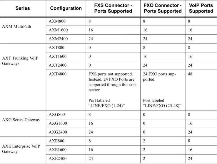
The Tenor AX is a high-density VoiP (Voice over Internet Protocol) H.323/SIP switch that com-presses and packetizes voice, fax, and modem data and transmits it over the IP network. Designed for Enterprises and Service Providers, the Tenor AX gives large businesses with analog voice infra-structure an easy, cost-effective way to capitalize on the power of Voice over IP (VoIP).
The Tenor AX integrates a gateway, gatekeeper, border element, intelligent call routing, and supports H.323/SIP and QoS all in one solution. The gateway converts circuit switched calls to VoIP calls, the gatekeeper performs IP call routing functions, and the border element distributes the call routing directories throughout the network. Through the FXS port, you can connect to a telephone, key sys-tem or PBX; through the FXO port, you can connect to the PSTN (through direct connection to the Central Office).
Figure 1-1 Tenor AX VoIP Switch
The Tenor AX is available in four series types:
• AXM MultiPath.The AXM MultiPath Switch is mainly intended for symmetrical multipath applications for typical enterprise applications. The number of FXS (i.e., PBX) ports is equal to the number of FXO (i.e., PSTN) ports. The number of VoIP channels is half the number of PSTN channels. Calls are routed between the Phone/FXS, Line/FXO, and the IP Network.
• AXT Trunking VoIP Gateway.The AXT Trunking VoIP Gateway is mainly intended for trunk side connections between the PSTN and the VoIP network. The number of VoIP ports is equal to the number of FXO ports. Calls can be routed in any direction between any of the ports. • AXG VoIP Gateway. The AXG VoIP Gateway is mainly intended for applications interfacing
between the PBX and the VoIP network. The number of VoIP channels equals the number of FXS ports. Calls can be routed in any direction between any of the ports.
• AXE Enterprise VoIP Gateway (plus 2 FXO ports). The AXE VoIP Gateway is mainly intended for applications interfacing between the PBX and the VoIP network, but it also includes two FXO ports for autoswitching to PSTN back-up and 911 service.
Table 2-1 Tenor AX Configuration Types
The MultiPath version’s architecture enables the Tenor AX to intelligently route calls between the FXS, FXO, and the VoIP network to achieve the best combination of cost and quality. The Tenor AX also routes calls over IP to reduce costs, and then transparently “hop off” to the PSTN, to reach off-net locations. Calls can be routed in any direction between any of the ports.
Whichever configuration you choose, the high performance unit provides one 10/100 BaseT con-nection, along with one RS-232 serial console port connection. The unit also incorporates an intelli-gent call routing engine which regulates system resources and configuration while coordinating all voice traffic activity in the unit.
The unit’s simple plug and play embedded system architecture brings VoIP technology to your net-work without changing your existing telephony infrastructure. Your netnet-work stays as is, and the call type is transparent to the user. This technology boasts superior voice quality without compromising reliability.
Series Configuration FXS Connector -
Ports Supported FXO Connector - Ports Supported VoIP Ports Supported AXM MultiPath AXM800 8 8 8 AXM1600 16 16 16 AXM2400 24 24 24
AXT Trunking VoIP Gateways
AXT800 0 8 8
AXT1600 0 16 16
AXT2400 0 24 24
AXT4800 FXS ports not supported. Instead, 24 FXO Ports are supported through this con-nector.
Port labeled
“LINE/FXO (1-24)”
24 FXO ports sup-ported.
Port labeled
“LINE/FXO (25-48)” 48
AXG Series Gateway
AXG800 8 0 8
AXG1600 16 0 16
AXG2400 24 0 24
AXE Enterprise VoIP Gateway
AXE800 8 2 8
AXE1600 16 2 16
Chapter 1: Overview
Features
The Tenor AX’s specific features are explained below. Unique Design
Tenor AX packs powerful VoIP features into one compact unit. The Tenor can be installed without upgrades to the existing voice or data network. You can install the unit anywhere, without affecting the network infrastructure you already have in place. As with all Tenor architecture, the Tenor AX provides the power of VoIP in a easy-to-use product that takes just minutes to get up and running. State-of-the-Art GUI Configuration and Network Management
The Tenor AX is managed by a two unique systems: Tenor Configuration Manager and Tenor Moni-tor. Through the Tenor Configuration Manager, you can configure all options, such as dial plans, call routing numbers, etc. via a simple Graphical User Interface (GUI). An easy-to-use installation process enables you to an install the manager and start configuring within minutes. Through the Tenor Monitor, you can monitor the health of the system, including alarms, call detail records, etc. Both the Tenor Configuration Manager and the Tenor Monitor provide comprehensive on-line help systems that are available at your fingertips.
In addition, you can configure the unit via Command Line Interface (CLI). Through this simple tel-net session, you can access all configuration options, including an online help system, built into the CLI, which provides help for all features and functions. Just type help at any prompt, and data about that field will be displayed.
Easy Connect to Console
Plugging a serial cable between the unit’s RS-232 port and your PC’s console port, will allow unit management.Through the console connection, you are able to assign an IP address. In addition, through the RS-232 port, you are able to configure the unit via Command Line Interface (CLI). Powerful System Monitoring
There are many different ways to monitor the health of the unit, including LEDs and alarms. LEDs appear on the front of the unit. The LEDs light up according to operations and alarms the system is experiencing.
For more advanced monitoring, you can use the Tenor Monitor and the Command Line Interface (CLI) to view a list of active system alarms, as well as view an alarm history. Each alarm indicates the unit’s operational status.
Capabilities
SelectNet™ Technology Safety Net (for Tenor AXM and Tenor AXE configurations) Quality of service is virtually guaranteed. Tenor AX ’s built-in patented SelectNet
™
Technology provides a “safety net,” which virtually guarantees that each call going VoIP will not only be routed successfully, but will deliver high voice quality.SelectNet monitors the IP network performance for VoIP calls. If the performance characteristics become unacceptable—according to the delay, jitter, and packet loss specifications you configure— the Tenor AX will switch the call to the PSTN automatically and transparently. The Tenor continu-ously monitors your data network and transparently switches customer calls to the PSTN when required.
PacketSaver™ reduces bandwidth consumption
PacketSaver packet multiplexing technology reduces the amount of IP bandwidth required to sup-port multiple calls flowing between two endpoints. PacketSaver minimizes bandwidth usage by aggregating samples from multiple VoIP conversations and packing them into a larger IP packet with a single IP header. The process removes the need to send a bulky IP header with individual voice packets. As a result, it eliminates the transmission of redundant information.
Figure 1-2 PacketSaver
Virtual Tie Trunk
The Tenor unit can emulate any tie trunk. It provides all of the functionality of a tie trunk, including the considerable cost savings, but eliminates the need for a PBX trunk to be configured, or marked as a tie trunk. (A traditional tie trunk is a PBX-configured direct connection between two PBXs in separate locations. The tie trunk bypasses the PSTN network, which results in considerable savings.) Your PBX does not need any additional configuration. The Tenor AX treats all trunks the same with-out compromising voice quality.
Conventional VoIP Transmission Sends Many Redundant Packet Headers
Tenor Tenor
Tenor using PacketSaver to Minimize Bandwidth Usage
Chapter 1: Overview SNMP Support
The Tenor AX supports Simple Network Management Protocol (SNMP), the standard protocol used to exchange network information between different types of networks.
Call Detail Recording
Through the Call Detail Record (CDR) feature, the Tenor AX generates a call record at the comple-tion of each call, typically for accounting purposes. A CDR is a string of data that contains call information such as call date and time, call duration, calling party, and called party. Tenor AX may store Call Detail Records locally or they can be sent to a CDR server within the network. The CDR contains sufficient information to capture billing data, which can be used to create billing reports using third party billing software.
IVR/RADIUS Support
Interactive Voice Response (IVR) is a feature of the Tenor AX that enables you to offer services, such as Pre-paid calling cards and Post-paid accounts, to your customers.
The Tenor uses the RADIUS (Remote Authentication Dial-In User Service), for authenticating and authorizing user access to the VoIP network, including ANI Authentication (Types 1 and 2). The RADIUS is a standard protocol which provides a series of standardized message formats for trans-mitting and receiving dialed information, account data and authorization codes between the network access gateway and the billing server.
NATAccess™
NATAccess is an intelligent network address translation technology. It enables VoIP networks with multiple endpoints to operate behind firewalls equippped with H.323 Network Address Translation (NAT); this provides maximum network security. NATAccess simplifies deployment by eliminating the need to place the Tenor on a public IP network. Using NATAccess provides easy, secure expan-sion between multiple VoIP sites. In addition, NAT technology in the Tenor permits the use of pri-vate subnets at the same time; in-house calls will never go over the public internet.
Figure 1-3 Tenor with NATAccess Deployment “Public” LAN Firewall NAT “Private” LAN “Private” port “DMZ” Port “DMZ” LAN Router
Dynamic Call Routing
Tenor AX’s intelligent call routing capabilities are state-of-the-art. The unit automatically detects and supports three call types: voice, fax, and modem.
Tenor AX will first identify the call origination site—Line/FXO, Phone/FXS, or IP routing group — and then route the call according to the parameters you have configured in the routing database. Each call may be routed via circuit switched path between any two circuit groups, or compressed and transported via VoIP when connecting to an IP routing group. Trunk circuits are those that typi-cally connect to another circuit switched network such as the PSTN. Line circuits typitypi-cally connect to a termination device on the user premises, such as a PBX.
Chapter 1: Overview
Tenor AX Call Paths
Tenor AXM MultiPath Switch (AXM800, AXM1600, AXM2400) Configuration The Tenor AX VoIP MultiPath Switch Configuration is symmetrical with an equal number of Phone/FXS and Line/FXO ports. Calls are routed from the Phone/FXS, Line/FXO, or IP Network. Calls can be routed in any direction between any of the ports.
Below are descriptions of the basic call paths from the FXS (Phone), FXO (Line) and IP; the exact call path will be determined by the specific Tenor AX configuration you have in your network.
FXS (Phone) Originated Calls. Calls coming from the Phone/FXS interface (i.e.PBX) may be switched to either the data network as a VoIP call or to the FXO interface, typically for connection to another circuit switched network such as the PSTN. The routing decision made by the Tenor AX is based upon your configuration and the dialed number. See Figure 1-4 for an example of a call origi-nated from a PBX.
Figure 1-4 FXS (Phone) Originated Calls
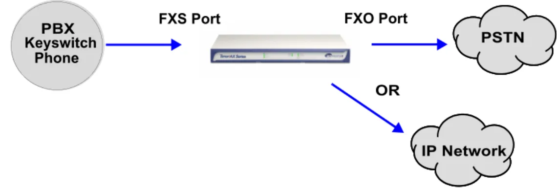
FXO (Line) Originated Calls. A call coming from a Line/FXO interface may be switched to either the data network as a VoIP call, a Line Circuit, or trunk typically for connection to a termination device on the user’s premises such as a PBX. The routing decision made by the Tenor AX is based upon your configuration and the dialed number. See Figure 1-5 for an example of a call originated from the PSTN.
Figure 1-5 FXO (Line) Originated Calls Keyswitch
Phone
PBX PSTN
IP Network OR
FXS Port FXO Port
Keyswitch Phone
PBX
PSTN
FXS Port FXO Port
IP Network OR
IP Network Calls. Calls coming from the IP network data can be routed to the Line/FXO or Phone/ FXS interfaces. The Tenor will route calls based upon the dialed number. If the number is config-ured as a local phone number, the call will be sent to a Phone/FXS circuit for termination, otherwise the call is considered a “Hop-Off call” and the Tenor sends it out through a Line/FXO interface, typ-ically connected to the PSTN. See Figure 1-6 for an example of a call originated from the IP net-work.
Figure 1-6 IP Network Originated Calls
Keyswitch Phone PBX PSTN IP Network OR
Chapter 1: Overview
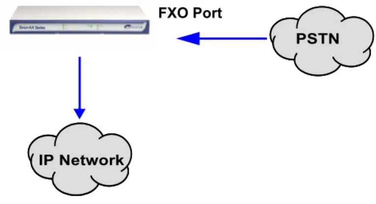
Tenor AXT Trunking VoIP Gateway (AXT800, AXT1600, AXT2400, AXT4800) Configu-ration
The Tenor AXT Trunking VoIP Gateway Configuration is used for trunk side PSTN (Line/FXO port) to VoIP connections; calls coming from the Line/FXO interface (i.e.PSTN) may be switched to the data network as a VoIP call. Calls can be routed in any direction between any of the ports. See
Figure 1-7 for an example of a call originating from the PSTN.
Figure 1-7 Tenor AXT FXO/Line Originated Call Sample
Tenor AXG VoIP Gateway (AXG800, AXG1600, AXG2400) Configuration
The Tenor AXG VoIP Gateway Configuration is used for (Phone/FXS) to VoIP connections; calls coming from the Phone/FXS interface (i.e. PBX) may be switched as a VoIP call. Calls can be routed in any direction between any of the ports. See Figure 1-8 for an example of a call originating from the Phone/FXS side (PBX).
See Figure 1-8 for an example of a call originating from a PBX.
Figure 1-8 Tenor AXG Phone/FXS Originated Call Sample IP Network PSTN FXO Port Keyswitch Phone PBX IP Network FXS Port
Tenor AXE Enterprise VoIP Gateway (AXE800, AXE1600, AXE2400) Configuration The Tenor AXE Enterprise VoIP Gateway is mainly intended for applications interfacing between the PBX and the VoIP network, but it also includes two FXO ports for autoswitching PSTN back-up and 911 service provision. The number of VoIP ports is equal to the number of FXS ports. Calls can be routed in any direction between any of the ports.
See Figure 1-9 for an example of a call originating from a PBX.
Figure 1-9 Tenor AXE Phone/FXS Originated Call Sample
Keyswitch Phone
PBX
PSTN
IP Network
Chapter 1: Overview
Advanced Features/Capabilities
Call Management
There are four types of routing databases you can configure: Bypass Directory Numbers (BPN), Hunt Local Directory Numbers (Hunt LDN), Hop-Off Directory Numbers (HDN), and Static Routes.
Bypass Directory Numbers. Bypass Directory Numbers (BDN) are telephone numbers that are automatically routed directly from a line circuit to the PSTN; they will not be routed VoIP. Some examples of bypass numbers include toll-free calls, emergency calls (i.e., 911), or high security calls.
Hunt Local Directory Numbers. A Hunt Local Directory Number (Hunt LDN) is aphone number reachable through local Line Circuits.
Hop-Off Directory Number. A Hop-off PBX call travels over IP, and then “hops” off into the pub-lic network (PSTN) on the distant side to reduce or eliminate pubpub-lic toll charges (also known as Leaky Area Map). A Hop-Off Directory Number is routed over the IP to another Tenor location and then out to the Trunk circuit, possibly to the PSTN as a local call.
Static Routes. Static Routes are used between networks and other H.323 devices that are not regis-tered to the network through the Border Element (such as non-Quintum gateways). A static route associates endpoints (as represented by their IP address) with Directory Number patterns. Dial Plan Options
Public/Private Dial Plan Support.The Tenor AX supports public and private dial plans. A public dial plan includes numbers which conform to the international dialing plan (E.164) of a country code + city/area code + local number. For a public dial plan, you can define the numbering plan structure for the Tenor AX to use for outgoing calls.
A private dial plan does not conform to a public dialing plan (i.e., 3 digit dialing plan); through the Tenor AX you are able to configure the unique pattern/dialing plan structure, including number length.
You are able to configure which dial plan to use for incoming and outgoing calls, including whether other options such as hop-off calls, will use a public or private dial plan.
User Programmable Dial Plan Support. The User Programmable Dial Plan Support (UPDP) enables the Tenor to identify a completely customizable set of digit sequences, such as Local, National, International or Private Numbers.
PassThrough support for certain call types. Certain call types can be directly routed to a trunk circuit, without going IP. There are several routing tables you can configure through the Tenor Con-figuration Manager to adjust how the Tenor AX unit routes these types of “pass through” numbers. For example, you may want to configure 911 as a “bypass number”, which means that all 911 calls coming into Tenor AX from the line circuit will be routed directly to a Trunk circuit presumably con-nected to a PSTN. Bypass calls are never routed over IP.
Hop-off PBX Calls. Hop-off numbers are phone number patterns for calls to be routed out to the PSTN. (A hop-off PBX call is a toll call which hops through a private network to reduce or elimi-nate the toll charge.) They are entered in a Hop-off Number Directory and associated with trunks where matching calls should be sent.
Tenor AX supports those hop-off PBX calls where the destination Tenor AX is programmed to route the call to the PSTN. The destination Tenor AX unit is configured with the phone numbers to be “supported” for this feature.
H.323 Gatekeeper Services
The Tenor AX unit’s built-in H.323 gatekeeper performs IP call routing functions, such as call con-trol and administrative services to another Tenor AX unit, or another H.323 endpoint. The gate-keeper’s functionality complies with the H.323 industry specifications for voice control and management.
Gatekeeper. A Gatekeeper in an H.323 network provides call control services and other services to H.323 endpoints (i.e., gateways, terminals, and MCUs). The Tenor AX has a built-in H.323 gate-keeper which complies to the H.323 industry specifications for voice control and management. The gatekeeper performs call routing functions for calls entering and exiting a site.
The Gatekeeper performs IP call routing functions, such as Call Control Signaling and Call Authori-zation for Gateways, IP phones, and H.323 terminals. The Gatekeeper communicates with other Gatekeepers through a Border Element. When using a group of Tenor AX units, you can assign one unit as the Gatekeeper for the network. We recommend you configure each as its own gatekeeper. Tenor AX supports gatekeeper to gatekeeper communication using the standard LRQ (Location Request)/LCF (Location Confirm) messaging scheme.
Zone Management. A zone is a group of H.323 defined endpoints controlled by a Gatekeeper. End-points can be gateways (i.e., Tenor AX), terminals, and/or multipoint conferencing units (MCUs). Endpoints establish control channels with a gatekeeper for registration, admission, and security. Call routing information about the endpoint is sent to the gatekeeper, including: IP address, unit type (gateway, terminal, or MCU) and routing information (such as phone numbers, number patterns, etc.).
A collection of zones is an administrative domain. An administrative domain provides call routing services for its zones through gatekeeper to gatekeeper messages or gatekeeper to border element messages (see below for more information).
Call Registration. When registration from an H.323 endpoint is complete and a call is originated, the call request is sent to the gatekeeper. The call request provides the Gatekeeper with the dialed number and requests the routing information. The gatekeeper confirms the dialed number and sup-plies the endpoint with the destination IP address. For example, a Tenor AX’s gatekeeper will act as the gatekeeper for that zone and all of the other endpoints will register with it.
Border Element. The Tenor AX’s gatekeeper uses a border element to gain access to the routing database of the administrative domain for the purpose of call completion or any other services that involve communications with other endpoints out of the administrative domain. The border element functionality is built into the Tenor AX unit, along with the gateway and gatekeeper.
Chapter 1: Overview The primary function of the border element is to collect, manage, and distribute call routing infor-mation. A gatekeeper will establish a service relationship with a border element; the gatekeeper pro-vides its zones capabilities and the border element shares call routing capabilities of other zones in the administrative domain. Through the border element, gatekeepers from multiple zones will be able to communicate.
A border element also establishes relationships with other border elements to route between admin-istrative domains. If a gatekeeper cannot resolve an address, it contacts the border element.
In addition, if you are using more than one Tenor unit, you can configure one of the border elements for that zone. The Tenor AX unit can use two border elements: primary and secondary. These work together as one entity to provide redundancy and fault tolerance; there are no hierarchal differences.
Call Services. Gatekeepers provide services such as addressing, authorization and authentication of terminals and gateways, bandwidth management, accounting, billing, and charging. Gatekeepers also provide call-routing services. Specifically, the Tenor AX Gatekeeper provides the functions which follow:
Address Translation. The gatekeeper translates telephone numbers into IP addresses and vice versa. It performs Alias Address (phone number) to Transport Address (IP address) translation when an endpoint requests service. The Gatekeeper uses a translation table to translate an Alias Address (an address such as an H.323 identifier that a user may not understand) to a transport address. The translation table is updated using Registration messages.
Autodiscovery. The gatekeeper is discovered in one of the following ways: An endpoint sends an IP broadcast called a Gatekeeper Request message (GRQ) message (which includes that correct gate-keeper name) to discover a Gategate-keeper OR the endpoint will discover a gategate-keeper by its IP address.
Routing. The gatekeeper identifies the IP address of endpoints in its administrative domain. The gatekeeper builds a routing database from information obtained from the border element and also from gateways and H.323 endpoints.
Admissions Control. All H.323 endpoints must register and request permission to enter the gate-keeper’s zone; the gatekeeper will confirm or deny access to the network. The gatekeeper authorizes
Border Element Gatekeeper Zone Gatekeeper Zone Gatekeeper Zone Administrative Domain Border Element Gatekeeper Zone Gatekeeper Zone Gatekeeper Zone Administrative Domain
network access and protects the integrity of the network using Admissions Request (ARQ), Admis-sions Confirmation (ACF) and AdmisAdmis-sions Reject (ARJ) messages.
SIP User Agent
SIP (Session Initiation Protocol) is a signaling protocol used to establish a session on an IP network for voice control and management; it is a request-response protocol that closely resembles Hypertext Transfer Protocol (HTTP), which forms the basis of the World Wide Web. SIP re-uses many of the constructs and concepts of Internet protocols such as HTTP and Simple Mail Transfer Protocol (SMTP). The purpose of SIP is only to establish/change/terminate sessions. SIP is not concerned with the content or details of the session.
SIP is Transport layer-independent, which means it can be used with any transport protocol: UDP, TCP, ATM, etc. It is text-based, so it requires no encoding/decoding like H.323. And SIP supports user mobility, using proxies and redirecting requests to your current location.
When configured for SIP the Tenor will act as a SIP User Agent (Endpoint) as defined in IETF RFC3261. Multiple user agents allow for separate agents to be allocated to each SIP call. It will be able to gateway calls to and from the IP network, and Customer Premise Equipment (CPE) such as phones, PBX's, and FAX machines, or the Public Switched Telephone Network (PSTN). The Tenor SIP User Agent will work in conjunction with an external SIP proxy or redirect to route and connect calls over SIP based networks.
There are three basic components of SIP: 1. User Agent (Endpoint)
• client element, initiates calls • server element, answers calls
2. Network Server (Proxy Server or Redirect Server) • name resolution
• user location • redirect and forking 3. Registrar
C
hapter 2: Hardware Components
This chapter tells you what is contained in your hardware package. A description of each component is also included.
Specifically, the following topics are covered:
Hardware Description Cables
Hardware Description
The Tenor AX is a stackable device which provides Phone/FXS and Line/FXO connections as well as connections to the Ethernet LAN and a PC.
The unit’s front panel includes LEDs; the back panel includes connection jacks, a diagnostics option, a reset button, and an on/off power switch.
Front Panel Connections and Reset Options
Figure 2-1 Tenor AX Front Panel
The LEDs display the health of the system. There are different types of LEDs: Power, Status, LAN, and Analog Port. See Table 2-1 for a description.
Table 2-1 Front Panel LEDs Definitions
LED Label LED Color Description
Power Power Green On: Indicates power is on.
Off: Power is off. Status Status Green Flashing Operational Status.
Off: Tenor AX is working properly. On: One or more diagnostic tests have failed.
Analog Port
Line/FXO Phone/FXS
Line/FXO LED - Green On indicates activity is occurring on at least one Line/FXO port. Phone/FXS LED - Green On indicates activity is occurring
on at least one Phone/FXS port. Power LED
LAN LEDs Analog Port LEDs
Chapter 2: Hardware Components
LAN
100Mb Green On: The advertised link rate is
100Mb if the link is not connected, or the actual link rate is 100b if the link is connected.
Off: The advertised link rate is 10Mb if the link is not connected, or the actual link rate is 10Mb if the link is connected.
Link Green On: Link is working properly and
there is activity on the line. Off: Link has failed.
Activity Green Flashing On: Indicates there is activity (i.e., transmit/receive) on the line. Off: No activity is occurring.
Back Panel
• Phone/FXS port. Provides a 50 Pin Telco connector which supports up to 24 Phone/FXS con-nections for connecting to the PBX, Keyphone or phones. For the AXT4800, this supports Line/FXO capability, and is labeled LINE/FXO (1-24).
• Line/FXO port. Provides a 50 Pin Telco connector which supports up to 24 Line/FXO connec-tions for connection to the Central Office (connection to the PSTN). For the AXT4800, this is labeled LINE/FXO (25-48).
• LAN port. 10/100 Base-T Ethernet port. This port provides an RJ-45 jack for individual con-nection to a 10/100 Ethernet LAN switch or hub via RJ-45 cable; it is individually configured with a unique IP and MAC address.
Figure 2-2 10/100 BASE-T Ethernet Port Pin Order
Table 2-2 Input/Output 10/100 Ethernet port
Pin # Signal Definition Color
1 TX + Transmit Data White w/orange
2 TX - Transmit Data Orange
3 RX + Receive Data White w/green
Phone/FXS port Line/FXO port
LAN port Console Port Diag Reset Power Switch Power Receptacle For AXT4800 only,
this is labeled LINE/FXO(1-24)
For AXT4800 only, this is labeled LINE/FXO(25-48)
Chapter 2: Hardware Components
• Console port. This RS-232 connector is used for connection to a PC’s serial port via DB-9 serial cable at 38400 BPS 8N1, without flow control. The input/output signals are listed in
Table 2-3.
Figure 2-3 DB-9 Female Connector Pin Order
Table 2-3 Serial RS232 DB-9 Connector Pinouts
• Diag. Enables you to perform software diagnostic procedures.
• Reset. Enables you to reset the system. See Chapter 4: Advanced Topic: Diagnostics/Mainte-nance for more information.
• Power Switch. Switch to turn power on and off.
• Power Receptacle. Connection port for connection to an AC outlet for power.
4 RSVD Reserved Blue
5 RSVD Reserved White w/blue
6 RX - Receive Data Green
7 RSVD Reserved White w/Brown
8 RSVD Reserved Brown
Pin # Function Description
1 DTR Data Terminal Ready
2 TXD Transmit Data 3 RXD Receive Data 4 CD Carrier Detect 5 GND Signal Ground 6 N.C. No Connect 7 N.C. No Connect 8 N.C. No Connect 9 N.C. No Connect
Pin # Signal Definition Color
5 4 3 2 1
Cables
The cables listed in Table 2-4 are required to connect a Tenor AX to various interfaces. Contact Quintum for ordering information, if necessary.
Table 2-4 Cables Supported
Cable Usage
50-Pin Telco Connector Connection to FXO/Line Connection to FXS/Phone
RJ-45 Ethernet cable Connection to Ethernet LAN 10/100
DB-9 Serial RS-232 Connection to PC’s asynchronous console port Detachable (IEC) AC Power Supply Cord Connection to AC power jack.
Chapter 2: Hardware Components 50-Pin Cable
The 50-pin Telco shielded cable connection pinouts and wire colors are given in this section to help you identify the proper specifications for connection to the FXO/Line and FXS/Phone ports. For the 50-pin Telco cable, terminate only one end with a Female, AMP 50-pin Telco Connector with 180 degree entry. Cable must consist of 25 twisted pairs color coded per Figure 2-4 and be of 22 or 24 AWG copper wire.
Figure 2-4 50-Pin Cable Connector Specifications
Connector Wire Color Wire Band DSO #'s Pin #'s Tip wire Ring wire Pin # Color w/ Color
1 Blue / White 1 1 & 26 26 1 Slot 1 line 1 2 Orange / White 2 2 & 27 27 2 Slot 1 line 2 3 Green / White 3 3 & 28 28 3 Slot 2 line 1 4 Brown / White 4 4 & 29 29 4 Slot 2 line 2 5 Slate / White 5 5 & 30 30 5 Slot 3 line 1 6 Blue / Red 6 6 & 31 31 6 Slot 3 line 2 7 Orange / Red 7 7 & 32 32 7 Slot 4 line 1 8 Green / Red 8 8 & 33 33 8 Slot 4 line 2 9 Brown / Red 9 9 & 34 34 9 Slot 5 line 1 10 Slate / Red 10 10 & 35 35 10 Slot 5 line 2 11 Blue / Black 11 11 & 36 36 11 Slot 6 line 1 12 Orange / Black 12 12 & 37 37 12 Slot 6 line 2 13 Green / Black 13 13 & 38 38 13 Slot 7 line 1 14 Brown / Black 14 14 & 39 39 14 Slot 7 line 2 15 Slate / Black 15 15 & 40 40 15 Slot 8 line 1 16 Blue / Yellow 16 16 & 41 41 16 Slot 8 line 2 17 Orange / Yellow 17 17 & 42 42 17 Slot 9 line 1 18 Green / Yellow 18 18 & 43 43 18 Slot 9 line 2 19 Brown / Yellow 19 19 & 44 44 19 Slot 10 line 1 20 Slate / Yellow 20 20 & 45 45 20 Slot 10 line 2 21 Blue / Violet 21 21 & 46 46 21 Slot 11 line 1 22 Orange / Violet 22 22 & 47 47 22 Slot 11 line 2 23 Green / Violet 23 23 & 48 48 23 Slot 12 line 1 24 Brown / Violet 24 24 & 49 49 24 Slot 12 line 2 25 (Unused) Slate / Violet N/A 25 & 50 Un-used Un-used Un-used
26 White / Blue
27 White / Orange NOTE: Slot 1 is closest to the 50 Pin Telco
28 White / Green bulkhead connector on the chassis.
29 White / Brown 30 White / Slate 31 Red / Blue 32 Red / Orange 33 Red / Green 34 Red / Brown 35 Red / Slate 36 Black / Blue 37 Black / Orange 38 Black / Green 39 Black / Brown 40 Black / Slate 41 Yellow / Blue 42 Yellow / Orange 43 Yellow / Green 44 Yellow / Brown 45 Yellow / Slate 46 Violet / Blue 47 Violet / Orange 48 Violet / Green 49 Violet / Brown 50 (Unused) Violet / Slate
Chapter 2: Hardware Components RJ-45 Ethernet Cable (10/100)
The RJ-45 cable connector pinouts are given in this section to help you identify the proper connector to accommodate your specific networking requirements. The RJ-45 (ISO 8877) connector is the EIA/TIA standard for Unshielded Twisted Pair (UTP) cable; the wiring color codes are UTP Stan-dard Coloring. The pin order is shown in Figure 2-5.
Figure 2-5 RJ-45 Pin Order
An RJ-45 (10/100BaseT) straight through cable is used to connect Tenor AX to an Ethernet LAN. Cable pinouts are listed in Figure 2-6. Color specifications are applicable to the RJ-45 cable pro-vided.
Figure 2-6 RJ-45 (10/100BT) Connector Pinouts
Table 2-5 RJ-45 (10/100BT) Connector Pinouts
Pin # Signal Definition Color
1 TX + Transmit Data White w/orange
2 TX - Transmit Data Orange
3 RX + Receive Data White w/green
4 Unused Unused Blue
5 Unused Unused White w/blue
6 RX - Receive Data Green
7 Unused Unused White w/Brown
8 Unused Unused Brown
8 1 1 8 Side View Top View
Pin # Connects to Pin #
1 2 3 4 5 6 7 8 1 2 3 4 5 6 7 8
DB-9 Serial RS-232 Cable
The Serial RS-232 9-pin cable with a DB-9 male connector (with RS-232 interface) is used to con-nect the Tenor AX to your PC’s asynchronous serial port. The pin order for DB-9 male and female connectors are shown in Figure 2-7 and Figure 2-8.
Figure 2-7 DB-9 Male Connector Pin Order
Figure 2-8 DB-9 Female Connector Pin Order
Figure 2-9 DB-9 Connector Pinouts
Table 2-6 DB-9 Connector Pinouts
Pin # Function Description Pin #
1 DTR Data Terminal Ready 1
2 TXD TransmitData 2 3 RXD Receive Data 3 4 CD Carrier Detect 4 5 GND Signal Ground 5 6 N.C. No Connect 6 7 N.C. No Connect 7 8 N.C. No Connect 8 9 N.C. No Connect 9 1 2 3 4 5 6 7 8 9 5 4 3 2 1 9 8 7 6
Pin # Con nects to Pin #
1 2 3 4 5 6 7 8 9 1 2 3 4 5 6 7 8 9
Chapter 2: Hardware Components
Specifications
Voice/Fax
Call Routing: FXO/FXS/IP
Voice Algorithms: G.723.1A (5.3, 6.3 Kbps), G.726 (16, 24, 32, 40 Kbps), G.729A, G711 Fax Support: Group III at 2.4, 4.8, 7.2, 9.6, 12, 14.4 Kbps
Automatic Call Detection:Voice/Modem/Fax PSTN/PBX Connections
Interface: Analog, FXO Interface (PSTN side), FXS Interface (PBX side) Connector: 50-PIN Telco
Ringing Voltage: Adjustable/Country-specific Ringing Cadence: Adjustable/Country-specific Maximum Loop Current: 24 mA
Ringer Equivalence Number:3 up to 1000 feet of 24 AWG or heavier Ringing Frequency: Adjustable/Country-specific
LAN Connection
LAN Support: 10/100 Mbps Ethernet
Connection Type: Autosensing of speed and duplex Physical
Position: 19” (48.7 cm) rack mountable, desktop stackable, wall-mountable Depth: 10 3/4” (27.6 cm)
Length: 17 3/8” (44.5 cm) Height: 1 3/4” (4.5 cm) Weight: 10 lbs (4.55 kg) Electrical
Ethernet: Standard 10/100Base-T RJ-45 interface (IEEE 802.3) Connectors: 50-pin Telco Connector for FXO connection
50-Pin Telco Connector for FXS connection Console Port: RS-232/DB-9 Female
Power: AC Power at 100-240 volts and 50-60 Hz, 70 Watts max Environmental
Operating Temperature: 40° to 104 °F (5°-40° C) Operating Humidity: 20% to 80% non-condensing
Altitude: -200 to 10,000 feet, or -60 to 3,000 meters Storage Temperature: 14° to 140° F, or -10° to 60° C
C
hapter 3: Installation/Basic
Troubleshooting
This chapter gives you installation instructions, as well as how to position the Tenor AX successfully within your network. In addition, basic troubleshooting techniques are included.
Specifically, the following topics are covered:
Installation
Connect to Phone/FXS Connect to Line/FXO Connect to Ethernet LAN Connect to PC
Power up the System Assign IP Address Common Troubleshooting
Chapter 3: Installation/Basic Troubleshooting
Installation
Before you begin the actual installation, review the pre-installation guidelines which follow and inspect the package contents.
Pre-Installation Guidelines
• Always use an anti-static wrist strap when handling the unit.
• Do not open the unit cover. Inside parts have hazardous voltages and are extremely sensitive to static. If the unit has been opened, our warranty is void.
• Do not connect equipment in wet conditions and keep away from dusty areas.
• The area must not exceed the temperature and humidity guidelines outlined in Chapter 2: Hardware Components.
• Avoid exposing the unit to excessive vibrations. • Ensure no equipment is put on top of the unit.
• Ensure there is clearance between the fan intake/exhaust on the side of the unit to avoid airflow being blocked.
Inspect Package Contents
Before you install the hardware, ensure the following components are included in our shipment: • Tenor AX and Mounting Hardware
• 1 AC Power Cable
• 1 DB-9 RS-232 Serial Cable • RJ-45 Cable
• Product Guide in CD format
Rack Install
Locate the Tenor AX unit within the same area as your PBX, Ethernet hub, switch, router, and/or PSTN patch panel. The unit is intended to be installed in a 19” rack.
Mounting brackets are attached to the chassis; the rack is not included with your system. Included with the unit are the screws below. The sizes should allow installation in most racks. If your rack does not use the same size screws listed in the table, please consult the instructions you received with the rack.
Required Materials
• 19” rack (not included with system)
• #8 - 32 x 3/8 screws (qty: 2) (included with system) • screws as required by your rack manufacturer Install the unit in a rack as follows:
1. Choose a position for the unit within the rack.
WARNING: If the unit is the only equipment installed in the rack, ensure it is level with the rack to avoid the rack from becoming unbalanced. Mount as low as possible to avoid a high center of grav-ity.
2. Align the unit’s mounting brackets flush with the rack’s mounting holes and follow the vendor specific instructions for rack installation. The screws provided require a Phillips #2 screwdriver. 3. Ensure the unit is secured firmly to the rack.
Wall Mount
There are two mounting brackets available to mount the unit to the wall. Pre-installation Guidelines
• Ensure the wall is level and stable.
• Do not attach the unit to a temporary wall.
• Ensure the wall mounting area is within cord distance of the power outlet. Required Materials
• 2 wall mounting brackets (including 2 screws) • Drill
• 3/16 drill bit
• Measuring tape or ruler • Hammer
Chapter 3: Installation/Basic Troubleshooting Attach the unit to the wall as follows:
1. Determine the wall area to mount the unit. With chalk or a soft pencil, mark the install area according to Figure 3-1.
NOTE: Ensure the unit is level.
Figure 3-1 Wall Mounting Dimensions
2. Position and attach one mounting bracket to the unit using a screw existing in the system and one screw included with the package. See Figure 3-2.
3. Position and attach the other mounting bracket using a screw existing in the system and the remaining screw in the package. See Figure 3-2.
Figure 3-2 Wall Mount Installation
4. Mount the unit to the wall using the four remaining screws included with the system. 5. Ensure the unit is firmly mounted against the wall.
7 3/4” (19.9cm) 3/16”
Mounting Brackets
Note: Ensure unit is level.
Attach each bracket to the
unit using 1 screw already installed and 1 screw included
in the unit (unscrew and re-insert) with the package.
Unit Front
The fan needs to be pointed up (when viewed fromNote: Fan
Preparing the Single-ended or Double-ended Telco Cable
Depending on your order, you will have received either a double-ended or a single-ended 50-pin Telco cable. Follow these steps for preparing and installing the cables.
Single-ended 50-pin Cable
If you have ordered a single-ended shielded 50-pin Telco cable, you must prepare it for use with your specific application.
At the opposite end from the 50-pin connector, the cable is taped off. Follow this procedure. 1. Cut into the outer cable casing approximately two inches from the taped off end, and cut
length-wise toward the taped end of the cable. Spread the outer casing to expose the following elements: • foil shielding, containing the bundle of 25 twisted pairs.
• silver braided drain lead • silk cords
Figure 3-3 Cross-section of Cut Cable
2. Gather the silk cords and pull back along the cut end of the casing to expose the desired length. 3. Trim back the outer casing, the foil shielding, and the silk cords to fully expose the 25 twisted
pairs.
4. Cut the drain lead and twisted pairs past the point of the initial cut into the cable casing. This will prevent the use of any wires that may have been nicked in the initial cut.
5. Terminate the drain lead to an appropriate earth ground.
6. Terminate the twisted pairs to the customer-specific connections (see Figure 2-4 for the color-coded 50-pin cable specification).
7. Ensure the screws on the opposite end are hand-tightened (do not overtighten). Double-ended 50-pin Cable
1. Ensure that the screws are hand tightened at both ends, including the termination end (do not overtighten).
Drain Lead
Outer Cable Casing
25 Twisted Pairs Silk Cords
Chapter 3: Installation/Basic Troubleshooting Connect to Phone/FXS Interface
NOTE: For the AXT4800 product only, the Phone/FXS port interface has FXO capability, and is labeled “LINE/FXO (1-24)”.
Since there are many different PBX devices, key systems, fax machines and phones you can connect to the Tenor AX, the instructions which follow explain the general procedure for connecting an external device to the Phone/FXS port through the 50-pin Telco connector. Use the phone/FXS ports for on-premise wiring only.
A double ended Telco cable connects to PBXs or phone systems that are equipped with the appropri-ate 50-pin Telco interface. An un-terminappropri-ated cable can be used with a break out box or another type of termination device specific to your needs. See Chapter 2: Hardware Components for the 50-pin connector pinouts you can use to acquire another cable or adaptor that may be required to connect to the specific external device (i.e., PBX).
Figure 3-4 Connect to Phone/FXS port
Connect to Phone/FXS port as follows:
CAUTION: Connect the Phone/FXS ports to a telephone, fax machine, PBX or key system only. Connecting to other devices/networks (i.e., telephone wall jack) will cause damage to the unit.
The instructions below assume you are using a double ended 50-pin Telco cable. See Chapter 2: Hardware Components for pinout information.
1. Plug one end of the 50-pin Telco cable into the port labeled Phone/FXS. 50 Pin Telco Connector
PBX
Telephone
Fax
Break Out Box
PBX OR
2. Insert the other end of the 50-pin Telco cable into the appropriate port on the PBX, key system, or another device that connects interfaces, such as a break out box. For the PBX connection, see your PBX documentation port requirements for connection specifics.
Chapter 3: Installation/Basic Troubleshooting Connect to Line/FXO Interface
NOTE: For the AXT4800 product only, the Line/FXO interface is labeled “LINE/FXO (25-48)”. To connect to the Line/FXO port, you must first connect the analog phone lines to another piece of equipment that houses your telephone lines running to the PSTN, such as the patch panel, punch down block or wire wrap blocks. If you are unsure of the installation procedures, contact the net-work administrator or review the documentation you received with the PBX.
A double ended Telco cable connects to PBXs or phone systems that are equipped with the appropri-ate 50-pin Telco interface. An un-terminappropri-ated cable can be used with a punchdown box or another type of termination device specific to your needs.
See Chapter 2: Hardware Components for the RJ-11 cable pinouts you can use to acquire another cable or adaptor that may be required to connect to the specific external device.
Figure 3-5 Connect to Line/FXO Interface
1. Plug one end of the 50-pin Telco cable into the ports labeled Line/FXO. See Chapter 2: Hard-ware Components for cable pinouts.
2. Connect the other end of the 50-pin Telco cable into the networking equipment (i.e., patch panel) which houses your telephone lines.
NOTE: Connecting to the patch panel may require trained telephone personnel. 50 Pin Telco Connector
Punchdown block PSTN Patch Panel Punchdown Block OR
Connect to Ethernet LAN
You can use these instructions for general connection purposes only. The Ethernet hub/switch manu-facturer’s documentation should provide specific instructions for connection to another device, such as the Tenor AX.
Figure 3-6 Connect to Ethernet Hub/Switch
1. Plug one end RJ-45 Ethernet cable into the port labeled LAN.
2. Plug the other end of the cable into one of the Ethernet hub/switch ports. If a custom cable or adapter is required, see Chapter 2: Hardware Components for Ethernet RJ-45 10/100.
Data Network
Ethernet Hub/Switch RJ-45 Cable
Chapter 3: Installation/Basic Troubleshooting Connect to PC Console
You will need to connect the Tenor AX to your workstation’s serial port via RS-232 connection. (This connection will be used when you assign an IP address to the unit.) For the instructions below, it is assumed you are connecting to a Windows PC.
Figure 3-7 Connect to PC Com Port
1. Insert the male end of the DB-9 cable into the port labeled Console. (See Chapter 2: Hardware Components for RS-232 connector pinouts.)
2. Insert the female end of the DB-9 cable into your workstation’s serial console port (see your PC documentation for more information about this port).
Power up the System
Once you have all cables connected properly, you are ready to turn the system on as follows: 1. Plug in the power cord to an AC outlet.
2. Locate the on/off switch on the back of the unit and click the switch to On.
The unit will power up and the LEDs will flash and turn off; the power LED will remain lit. For information about the LEDs, see Chapter 2: Hardware Components.
Once the unit is powered up, you are ready to assign an IP address. See the following section Assign IP address.
Chapter 3: Installation/Basic Troubleshooting
Assign IP address
Before you can configure the Tenor AX, you need to assign a valid IP address. An IP address is a 32 bit (up to 12 numeric characters) address used to identify each network device in the TCP/IP net-work. If the unit does not have an IP address, data will not be able to be sent to or from the unit. Communication between the Tenor and the PC is enabled via RS-232 connection and terminal emu-lation software. The instructions below assume you are running HyperTerminal (running Windows 95 or later) on your PC. For all other terminal emulation packages, the specific Tenor commands used to assign the IP address will be the same, but the software specific instructions will be different. Consult the applicable documentation for more information.
You can re-configure the IP address using the procedure which follows. 1. Press the Tenor AX’s power switch to On.
1. Click on Start> Programs> Accessories> Communications>HyperTerminal> Run. The Connec-tion DescripConnec-tion window will be displayed.
2. Enter a connection name (i.e., name for each unit such as Tenor AX New Jersey). 3. Click Ok.
4. Choose the serial port on your PC from the Connect Using drop down list box (i.e., Direct to Com 1). Click Ok. The Com1 Properties window will be displayed. See Figure 3-8.
Figure 3-8 Port Settings Window
5. From the Bits Per Second drop down list box, choose 38400. 6. From the Data Bits drop down list box, choose 8.
7. From the Parity drop down list box, choose None. 8. From the Stop bits drop down list box, choose 1.
9. From the Flow control drop down list box, choose None.
10.Click Ok and a connection to the Tenor will be established. Information about the unit will scroll on the screen.
11.Enter login and password. Both are admin by default.
12.A message will appear on the screen “Tenor Analog does not have an Ethernet interface config-ured. Would you like to configure an Ethernet Interface?” (y/n).
13.Type y.
14.For IP Address, enter the IP address for the Tenor unit.
15.For Subnet Mask, enter the subnet mask. This address is used to differentiate the network portion of the IP address from the host portion of the IP address.
16.For Default Gateway, choose whether there should be a default gateway (router) which routes packet data outside of your LAN and enter its IP address.
17.A message will appear on the screen “Tenor Analog Ethernet Interface successfully configured.” The Tenor will restart using the new Ethernet settings.”
Tenor will restart using the new Ethernet settings. Change IP Address
You are able to change the IP address in which the unit is attached as follows: NOTE: The instructions below assume you are running Windows 2000 or above. 1. Press the Tenor AX’s power switch to On.
2. Click on Start> Programs> Accessories> Communications>HyperTerminal> Run. The Connec-tion DescripConnec-tion window will be displayed.
3. Enter a connection name (i.e., name for each unit such as Tenor AX New Jersey). 4. Click Ok.
5. Choose the serial port on your PC from the Connect Using drop down list box (i.e., Direct to Com 1). Click Ok. The Com1 Properties window will be displayed. See Figure 3-9.
Chapter 3: Installation/Basic Troubleshooting Figure 3-9 Port Settings Window
6. From the Bits Per Second drop down list box, choose 38400. 7. From the Data Bits drop down list box, choose 8.
8. From the Parity drop down list box, choose None. 9. From the Stop bits drop down list box, choose 1.
10.From the Flow control drop down list box, choose None.
11.Press the Tenor AX power switch to On. After the bootup sequence, the login prompt will appear. 12.Enter a login name. The default login name is admin.
13.Enter a password. The default password is admin. (Once you are up and running, changing the password is a good idea for security purposes). Step through each of the following parameters and enter the correct values for your installation: IP address, Sub-net Mask and Default Gateway.
14.At the Quintum prompt, type ei to reach the Ethernet prompt and then type config to change to the Configuration mode.
15.To set the IP address, type set ipa followed by the IP address.
16.To set the Subnet Mask, type set subnetmask, followed by the subnet mask. 17.Type siprd to change to the Static IP Route Directory.
18.To set the Default Gateway IP, type change 1 g followed by the IP address for the default gate-way IP.
20.Type maint to reach the maintenance mode and then mc. Type reset. A confirmation message will ask if you want to reset the unit. Type yes to reset the unit. The reboot enables the Tenor to incorporate the new settings.
Once the IP information is set, you are ready to configure the unit. See the Tenor Configuration Manager/Tenor Monitor User’s Guide and Command Line Interface (CLI) User Guide for specifics. Both documents are on the CDR ROM you received with the unit or you can download the latest documentation from www.quintum.com.
Chapter 3: Installation/Basic Troubleshooting
Getting Started with Configuration/Making the First Call
This section includes basic information for making the first call using VoIP and a Tenor AX; for an example, this call will enable you to dial Quintum Technology’s test unit and hear a recorded mes-sage. Once you have accomplished that, you can modify the configuration to meet your own specific needs.
For future calls, if you require detailed configuration information, see the Tenor Configuration Man-ager/Tenor Monitor User’s Guide and Command Line Interface (CLI) guide for detailed configura-tion informaconfigura-tion (both documents are located on the CDR ROM you received with the unit or you can download the latest documentation from www.quintum.com).
If you are using a cable modem, or a DSL modem and a firewall, specific instructions are included in this section, When configuring a firewall, set up a DMZ (this makes the firewall act as a switch so that all incoming IP traffic for the firewall’s WAN IP will be routed directly to the Tenor AX). If you are using a cable modem with No firewall, specific configuration options are also included.
Figure 3-10 Making the First Call
These instructions assume the unit is taken right from the box and in the default state from the fac-tory, and basic connections are made. See below for a list of prerequisites that must be met before making a call from the Tenor.
• An analog phone connected to the port labeled FXS.
• A connection between the Tenor’s port labeled Console and your workstation’s serial console port. See Installation.
• Tenor Configuration Manager software is loaded on your workstation.
• Through HyperTerminal, you have configured an Ethernet Interface by assigning an IP Address, Subnet Mask, and Default Gateway (see Assign IP address for more information). Execute the first call as follows:
NOTE: If the call does not connect or you encounter a problem, see Common Symptoms/Problems
or Chapter 4: Advanced Topic: Diagnostics/Maintenance for possible solutions. 1. Start the Configuration Manager.
2. At the prompt, enter the IP address for your unit and enter the default login and password (admin/admin).
3. At the Phone(FXS)/Line(FXO)> AnalogInterface-Line screen, enable all four lines (or two lines, depending upon the unit type) under FXO Channel Assignment. Click on Confirm/OK.
4. At the System-Wide Configuration> Dial Plan screen, enter an Area Code (default is 732) and check Use 10 Digit Local Dial. Clickon Confirm/OK.
Allows the unit to use the 732 area code for its call without having to dial a “1”.
5. At the System-Wide Configuration> Time Server screen, set the Primary Time Server IP Address to a standard Time Server IP Address. This is not a required entry for the first call, but it is a good idea to set it at this point.
Set the Secondary Time server IP Address to a standard Time Server IP Address. Set the UTC Offset to -5 hours.
Clickon Confirm/OK.
6. At the VoIP Configuration> Gatekeeper/Border Element screen, set the Primary Border Ele-ment IP Address (i.e.,
12.176.187.080
for Quintum’s test unit). Click on Confirm/OK.7. At the VoIP Configuration> H323 Signaling Group screen, set the Primary Gatekeeper IP (i.e., 208.226.140.40 for Quintum’s test unit) Clickon Confirm/OK.
Allows the unit to get the information it needs to route your phone call to a specific IP address. 8. At the System-Wide Configuration> Circuit Configuration> Line Routing Configuration> Hunt
LDN Directories> Hunt LDN Directory-pub 1 screen, enter a pattern. (i.e., 10 digit phone num-ber that will be assigned to the phone on your end). Click on Confirm/OK.
This provides the Gatekeeper with a phone number designation for your unit.
For use with a Cable Modem or DSL Modem and a Firewall only
9. At the Ethernet Configuration> Ethernet Interfaces> Ethernet Interface-1 screen and enter the
External NAT IP (this is the IP that the service provider assigns to the firewall WAN port). Click Confirm/OK. This was tested with a Linksys™ firewall. Other types may work as well and should be configured similarly.
For use with a Cable Modem and No Firewall only
10.At the Ethernet Configuration> Ethernet Interfaces> Ethernet Interface-1 screen, check the
Enable DHCP box. Click Confirm/OK.
This provides a way for your service provider to assign an IP to your unit which can then be reached by the Gatekeeper on the public internet.
Chapter 3: Installation/Basic Troubleshooting
12.Pick up the phone and hear dial tone. Dial 7324609000. The call should route to Quintum’s test unit and you should hear a recorded message.
When you
dial 7324609000 (ten-digits), your unit (the Gateway) consults the
Gate-keeper's table of phone number to IP translations (the Gatekeeper is an application or
function inside the test Gateway at 12.176.187.080), and sends the appropriate data to
the other endpoint (in this case, the Quintum test unit). The Gateway is merely another
function or application of 12.176.187.080 The Gateway functions allow the incoming
call to be connected to Quintum’s PBX.
Load Software Upgrade
To upgrade the software, download the upgrade from the CD ROM you received with the unit, or download the latest software/documentation from www.quintum.com.
Common Symptoms/Problems
Before you begin troubleshooting a potential malfunction, it is a good idea to check your basic hard-ware connections. See below.
• Ensure power cord is firmly installed in the back panel’s power jack and the other end is plugged into the AC power source.
• Ensure the unit’s power switch is in the On position.
• Verify that all RJ-45, 50-pin Telco connectors, and DB-9 cables fit snugly in each back panel jack. Faulty connections may cause a number of network interfacing or connection issues. If you suspect the problem to be on the network end, contact your Central Office to verify proper operation.
Below is a list of common symptoms and problems youmay encounter. Use this list as a guideline; if your problem is not listed, see Chapter 4: Advanced Topic: Diagnostics/Maintenance.
Table 3-1 Common Symptoms/Problems
Common Symptom/Problem Description/Solution
Unit will not turn on. Check AC power source. Communication between Tenor AX and the
FXO or FXS cannot be established.
There are several reasons why communication may not be successful. A few of the most common are listed below. Verify correct 50-pin Telco cables are installed in the Phone/FXS and Line/FXO ports.
Ensure the unit is on.
Network issues may cause a number of problems. Contact the Central Office to perform test procedures.
Communication with Command Line Inter-face (CLI) cannot be established using Tel-net.
The IP address of the Tenor AX unit may be incorrect. Check Ethernet cable.
Verify the IP address of Tenor AX. Check the Default Gate-way Subnet Mask. Check Ethernet connection via RS-232 connection.
Verify network connectivity using ping from another net-work host.
Communication with Ethernet Hub, or switch cannot be established.
Verify RJ-45 cable is firmly installed in the Ethernet port. Check MDI/MDIX configuration. Check duplex setting on the switch in which they were connected and the speed of 10MB or 100 MB.
Chapter 3: Installation/Basic Troubleshooting
Communication between computer’s COM port and Tenor AX serial port cannot be established.
Verify DB-9 cable is firmly placed in the unit’s console port and your PC’s serial port.
Verify Terminal port settings at 38400 BPS 8N1 No Flow Control.
Tenor AX cannot receive or transmit calls. Ensure FXO/FXS ports are working correctly. Generate alarm list for more information. Contact Central Office for interface issues.
C
hapter 4: Advanced Topic: Diagnostics/
Maintenance
This chapter explains the advanced topics for monitoring alarms and performing maintenance/diag-nostic procedures.
Monitor LEDs Monitor Alarms
Verify Unit Provisioning
Perform Maintenance Procedures Finding Additional Help