IMPROVING THE UNIFICATION OF SOFTWARE CLONES
USING TREE AND GRAPH MATCHING ALGORITHMS
Giri Panamoottil Krishnan
A thesis in
The Department of
Computer Science
Presented in Partial Fulfillment of the Requirements For the Degree of Master of Computer Science
Concordia University Montr´eal, Qu´ebec, Canada
April 2014 c
Concordia University
School of Graduate Studies
This is to certify that the thesis prepared
By: Giri Panamoottil Krishnan
Entitled: Improving the Unification of Software Clones using Tree and Graph Matching Algorithms
and submitted in partial fulfillment of the requirements for the degree of
Master of Computer Science
complies with the regulations of the University and meets the accepted standards with respect to originality and quality.
Signed by the final examining commitee:
Chair
Dr. Joey Paquet Examiner
Dr. Peter Rigby Examiner
Dr. Nikolaos Tsantalis Supervisor
Approved by
Chair of Department or Graduate Program Director
Dean of Faculty
Abstract
Improving the Unification of Software Clones using Tree and Graph Matching
Algorithms
Giri Panamoottil Krishnan
Code duplication is common in all kind of software systems and is one of the most troublesome hurdles in software maintenance and evolution activities. Even though these code clones are created for the reuse of some functionality, they usually go through several modifications after their initial introduction. This has a serious negative impact on the maintainability, comprehensibility, and evolution of software systems.
Existing code duplication can be eliminated by extracting the common functionality into a single module. In the past, several techniques have been developed for the detection and management of software clones. However, the unification and refactoring of software clones is still a challenging problem, since the existing tools are mostly focused on clone detection and there is no tool to find particularly refactoring-oriented clones. The programmers need to manually understand the clones returned by the clone detection tools, decide whether they should be refactored, and finally perform their refactoring. This obvious gap between the clone detection tools and the clone analysis tools, makes the refactoring tedious and the programmers reluctant towards refactoring duplicate codes.
In this thesis, an approach for the unification and refactoring of software clones that overcomes the limitations of previous approaches is presented. More specifically, the proposed technique is able to detect and parameterize non-trivial differences between the clones. Moreover, it can find a mapping between the statements of the clones that minimizes the number of differences. We have also defined preconditions in order to determine whether the duplicated code can be safely refactored to preserve the behavior of the existing code. We compared the proposed technique with
a competitive clone refactoring tool and concluded that our approach is able to find a significantly larger number of refactorable clones.
Acknowledgments
Foremost, I would like to express my sincere gratitude to my advisor Dr. Nikolaos Tsantalis. His enthusiasm and motivation helped me throughout the research and writing of this thesis. His proper guidance helped me publish papers in major conferences. He continuously supported me in improving my knowledge and ability to do the research.
Besides my advisor, I would like to thank my thesis examiners: Dr. Joey Paquet and Dr. Peter C. Rigby. I would like to thank other faculty members of the Department of Computer Science and Software Engineering as well, for the necessary guidance. I also take this opportunity to thank Institute for Co-Operative Education, Concordia for giving me a chance to explore the professional world of Canada.
I thank my fellow lab mates and my friends in Concordia University for all their support towards the completion of this thesis. I express my gratitude to the staff members of our university for their help in providing a clean and safe environment for me to work. Also, I would like to thank my family and my roommates for supporting me throughout my endeavors.
Last but not the least, I would like to thank NSERC and the Faculty of Engineering and Computer Science at Concordia University for their generous financial support of this project.
Contents
List of Figures ix List of Tables x 1 Introduction 1 1.1 Software Maintenance . . . 1 1.2 Refactoring . . . 31.3 Software Code Clones . . . 3
1.4 Software Clone Management . . . 5
1.5 Challenges Involved . . . 6
1.5.1 Determining Valid Clone Regions . . . 6
1.5.2 Optimal Statement Matching . . . 6
1.5.3 Non-trivial Differences . . . 7
1.5.4 Refactoring ofType-3 Clones . . . 8
1.5.5 Refactoring Sub-clones . . . 9
1.6 Motivation . . . 9
1.7 Overview of the approach . . . 10
1.8 Contributions . . . 11
1.9 Thesis Outline . . . 12
2.1 Program Dependence Graphs and their Applications . . . 13
2.2 PDG-based Mapping Techniques . . . 15
2.3 AST-based Mapping Techniques . . . 18
2.4 Clone Refactoring Techniques . . . 19
3 Clone Unification 23 3.1 Statement Matching . . . 24
3.1.1 Abstract Syntax Tree . . . 24
3.1.2 AST Matching . . . 25
3.1.3 Implementation Details . . . 26
3.2 Control Structure Matching . . . 29
3.2.1 Control Dependence Tree Representation . . . 31
3.2.2 Algorithm . . . 33
3.2.3 Working Example of bottomUpMatchAlgorithm . . . 36
3.3 PDG Matching . . . 36
3.3.1 Advantages of PDG Matching . . . 37
3.3.2 Why do we need the PDG Mapping to be Improved? . . . 37
3.3.3 Maximum Common Subgraph . . . 40
3.3.4 Divide-and-Conquer Algorithm . . . 41
3.3.5 Example for Divide-and-Conquer Algorithm . . . 45
3.4 Clone Refactoring . . . 48
3.4.1 Preconditions Related to Clone Differences . . . 48
3.4.2 Preconditions Related to Method Extraction . . . 51
4 Evaluation 53 4.1 Experiment . . . 54
4.2 Discussion . . . 55
4.4 Threats to Validity . . . 58
5 Conclusion and Future Work 59
List of Figures
1 Maintenance activities . . . 2
2 Example of invalid clone regions (highlighted in gray) . . . 7
3 Example of reordered conditional structures . . . 7
4 Example requiring a more advanced parameterization of differences . . . 8
5 Example ofType-3 clones (highlighted in gray) with a gap . . . 9
6 An example for PDG . . . 14
7 An example of application of Form Template Method . . . 21
8 An overview of the proposed technique . . . 23
9 A block of source code and the corresponding Abstract Syntax Tree . . . 25
10 Abstract Syntax Trees of two assignment statements . . . 28
11 Example clone candidates . . . 32
12 The Control Dependence Trees for the code fragments of Figure 11 . . . 33
13 Optimizing statement mapping . . . 39
14 The Control Dependence Trees for the code fragments of Figure 13 . . . 40
15 Example clone fragments from the open-source projectJFreeChart . . . 45
16 The Control Dependence Trees for the code fragments of Figure 15 . . . 46
17 Parameterization of a difference breaking an existing anti-dependence . . . 50
18 Beanplots for the numbers of node comparisons using a brute-force approach and our mapping approach . . . 57
List of Tables
1 Supported Expression Types In AST Matching . . . 26
2 Detected Differences Between Matched Nodes . . . 27
3 Execution Steps In AST Matching Process . . . 29
4 Mappings Found At Level 2 . . . 46
5 Mappings Found At Level 1 . . . 47
6 Refactorable Clone Groups Found By Eclipse, CeDAR And JDeodorant . . . 54
7 Additional Refactorable Clone Groups Found By JDeodorant . . . 55
Chapter 1
Introduction
This chapter introduces the preliminary concepts and motivation behind the thesis. It also briefly discusses how we tackle the challenges involved.
1.1
Software Maintenance
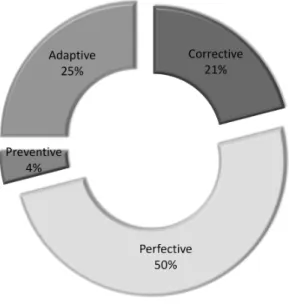
Maintenance and enhancement activities of a software application constitute a major share of the software life cycle. According to McKee [McK84], at least two thirds of the software activities are attributable to maintaining existing applications rather than creating new applications. Also, various surveys show that application program maintenance expenditures represent about 40-75% of the total application program expenditures [Gui83]. Software maintenance deals with the modification of a software product after delivery to correct faults, to improve performance or other attributes, or to adapt the software to a changed environment. Followed by the initial definition of maintenance activities by Swanson [Swa76], four categories of maintenance activity are distinguished as follows [BS87].
1. Corrective- consists of activities of repairing faults to keep the system operational.
2. Adaptive - initiated as a result of changes in the environment in which the system must operate.
Figure 1: Maintenance activities
3. Perfective - includes all changes and enhancements which are made to the system to meet the new or changed user requirements.
4. Preventive- concerns activities aimed at improving the future maintainability and reliability of the software system.
Lientz and Swanson [LS80] did a survey on software maintenance practices at 487 companies and found that most maintenance is perfective. At the same time, many empirical studies show that preventive maintenance corresponds to less than 5% of the total maintenance costs. The distribution of maintenance activities is shown in the Figure 1 [MM83] [SPL03] [Vli08]. The chart clearly shows that software industries invest more on maintenance activities leading to immediate benefits rather than preventive maintenance which leads to long-term benefits. This may be due to the lack of availability of efficient and user friendly tools aiming preventive maintenance, in the market. This thesis work focuses on the preventive maintenance of software systems as it deals with the refactoring of existing code to improve the future maintainability of the software.
A major problem which can evolve from poor maintenance activities is Legacy Crisis. The design quality of a software system tends to deteriorate with software aging. As a result, the companies invest more on maintenance activities, especially in modernizing legacy systems. If this
trend continues, there will be no resources left to develop new systems, and this reality is referred to as Legacy Crisis by Seacord et al. [SPL03]. One counteract to avoid this is improving the maintainability of the software through Preventive Maintenance.
1.2
Refactoring
“Refactoring is the process of changing a software system in such a way that it does not alter the external behavior of the code, yet improves the internal structure” [Fow99]. In other words, refactoring is done to improve the design of the existing code. Refactoring is supported by different IDEs like Eclipse. Programmers use two types of tactics to apply refactoring -floss refactoring and root-canal refactoring[MHPB09]. Floss refactoringis frequent and it is intermingled with other kind of program changes in order to maintain the code healthy. Root-canal refactoring is an infrequent long activity done exclusively to fix unhealthy code. Murphy-Hill and Black [MHB08] suggestfloss refactoring as the recommended tactic for the preventive maintenance of the code.
In refactoring process, the bad code is improved and thus the software quality is increased. Fowler [Fow99] calls the occurrences of substandard code quality as ‘bad smells’. Among the 22 bad smells identified [Fow99], he mentions ‘Duplicated Code’ as “the number one in stink parade”. We concentrate on this bad smell and here onwards, we call ‘Duplicated Code’ as ‘Code Clone’. The next section explains why code clones are a major problem in software programs.
1.3
Software Code Clones
Code duplication happens when a code fragment has other code fragments identical or similar to it somewhere in the software system. Duplicated code or code clones are common in all kinds of software systems. Typically, 10-15% of the software comprises code clones [KG08]. This is mainly because programmers find it easier to use copy-paste technique during programming in order to reuse some functionality. But, this causes software to be less maintainable. There is empirical evidence that duplicated code makes the maintenance of software more difficult.
1. Duplicated code increases significantly the maintenance effort and cost [LW08]
2. It is associated with error-proneness due to the inconsistent changing of clones [JDHW09]
3. It is more unstable than non-duplicated code [MRS+11] [MRS12] [MRS13].
Code duplication in general increases the code size and complexity, thus making the software maintenance difficult. This is often because any modification of original code should be applied to the code clones as well. For example, when enhancements or bug fixes are done on one copy of the duplicated code, we would need to find the other copies and fix them as well. This would be a major problem in software renovation projects and those projects where code changes are done quite often. If the developers forget to apply necessary changes in every instance of code clones, it will result in the inconsistent functioning of the software, which in turn causes expensive maintenance activities in future. The above mentioned reasons make code clones good candidates for software redesign. Therefore, it is of utmost importance to find code clones efficiently and remove them, i.e., to refactor the code such that only one copy of the code fragment is maintained.
Four types of code clones have been defined by the software clone community [DBFF95] [KFF06] [RC07].
1. Type-1 clones- Exactly identical code fragments except for differences in white spaces and comments.
2. Type-2 clones- Similar code snippets with variations in identifiers, literals and types.
3. Type-3 clones-Gappedcode fragments in which statements(one or more) have been added/deleted or modified beyond syntactic similarity.
4. Type-4 clones- Code fragments that perform the same calculation(logic) but with different syntax.
1.4
Software Clone Management
Software clone management comprises all activities of looking after and making decisions about consequences of copying and pasting [Kos08]. According to Koschke [Kos08], we can distinguish three main lines of clone management:
1. preventive, which comprises activities to avoid new clones,
2. compensative, which encompasses activities aimed at limiting the negative impact of existing clones that are to be left in the system and
3. corrective, which covers activities to remove clones from a system.
Recent research work has focused more on the preventive and compensative aspects by providing techniques for clone tracking [DER07], incremental clone detection and clone consistency analysis [NNP+12], and much less on the corrective aspect of clone management.
The best solution to avoid the existing duplicates of code fragments is to find a way to unify them. Existing code duplication can be eliminated by extracting the common functionality into a single module. However, the unification and refactoring of software clones is a challenging problem, since clones usually go through several modifications after their initial introduction. Both detection and elimination of code clones have been investigated before. Fowler presented a catalog of different techniques for refactoring, which have been widely followed by the refactoring community. Some of them which are relevant to this thesis are explained below.
1. Extract Method - When the clones belong to the same class, they are extracted into a new method and all the clone copies are replaced by calls to the new method.
2. Pull Up Method - This can be applied when the code clones (Type-1 and Type-2) lie in sibling subclasses. They are extracted into a new method created in their parent class.
3. Form Template Method - When the code clones are Type-3 and exist in sibling subclasses, duplicated code fragments are pulled up to the base class and the unique fragments remain in the derived classes.
1.5
Challenges Involved
Many code clone detection tools are available to identify all types of duplicated code. But they do not guarantee that all code clones identified by them arerefactoring-oriented code clones. Refactoring-oriented code clones are more suitable for refactoring than general code clones returned by the clone detection tools [HKI08]. Figure 2 shows an example of general code clones returned by a token-based clone detection tool. These clones cannot be directly refactored as discussed in the following sub-sections. So, the first challenge is to find code clones that can be unified for the purpose of refactoring. The major problems with using the output directly from code clone detection tools are listed below.
1.5.1
Determining Valid Clone Regions
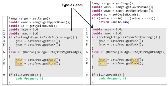
Most existing clone refactoring techniques [TG12, HKI08] recognize that the presence of valid clone regions (i.e., the regions in which the clones expand) is an important condition to enable the refac-toring of a clone group. A valid clone region is a region that does not contain incomplete statements. A statement is considered as incomplete if part of its expression(s) or body is not included in the clone region. The example shown in Figure 2 is a typical case of invalid clone regions (the lastif statement is incomplete in both clones).
1.5.2
Optimal Statement Matching
The differences of mapped statements may not be minimal. For example in Figure 2, line number 7 in the first clone and line number 8 in the second clone are exactly the same. Likewise, line number 8 in the first clone and line number 7 in the second clone are exactly the same. But, due to the insufficient information from the results of clone detection tools, the refactoring tool tends to map the statements in order i.e., line 7 with line 7 and line 8 with line 8. This problem should be addressed before refactoring, in order to minimize the number of differences and thereby the number of required parameters while extracting the code fragment into a separate method.
Figure 2: Example of invalid clone regions (highlighted in gray)
tools do not support the matching of the two code fragments shown in Figure 3 as the conditional structures are reordered. Looking for an optimal mapping of statements in the entire clone fragments will help us to determine that these two code fragments can be mapped indeed.
Figure 3: Example of reordered conditional structures
1.5.3
Non-trivial Differences
There are other challenges involved in unifying the code fragments. If Type-1 clones are easy and straightforward to merge, Type-2 clones often contain non-trivial differences. Type-2 clones are syntactically identical code fragments that differ in variable identifiers, method call identifiers, literals, and types. Type-2 clones can be refactored by mapping the differences among the clones
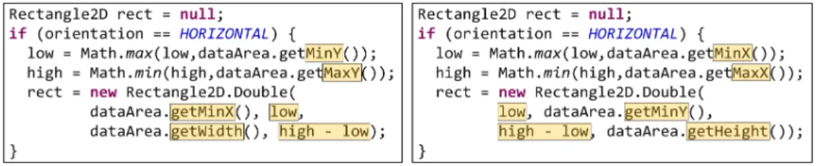
of a clone group and introducing a parameter of appropriate type in the extracted method for each parameterized difference. After the extraction of the duplicated code, the methods that originally contained the clones call the extracted method by passing as arguments the values corresponding to the parameterized differences. The majority of clone refactoring tools support the parameterization of differences in local variable identifiers. Recently, CeDAR [TG12] introduced the parameterization of differences in field accesses, method calls and literals. This extended parameterization enables the refactoring of clones containing dissimilarities between different types ofAST nodes (e.g., variables replaced with method calls). AST (Abstract Syntax Tree) is a tree-like representation of the source code where each node represents a code construct (Section 3.1.1). However, this approach would be ineffective in the example of Figure 4, because an entire expression (i.e.,high - low) is replaced with a method call. This example could be refactored only if parameterization took place at argument level (i.e., a higher level in the AST) and not at identifier level (i.e., AST leaves).
Figure 4: Example requiring a more advanced parameterization of differences
1.5.4
Refactoring of
Type-3
Clones
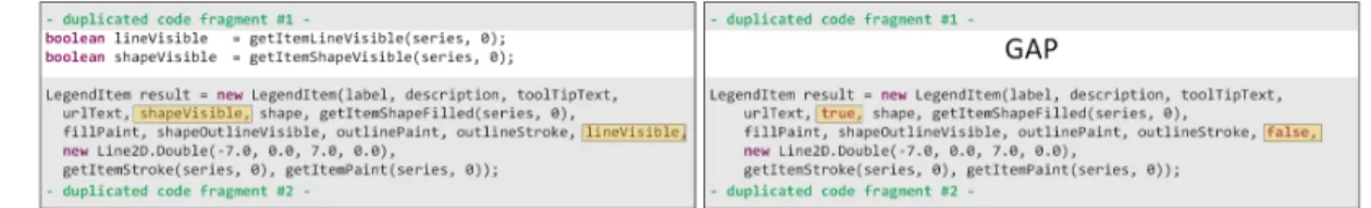
The refactoring of Type-3 clones is challenging due to the presence of unmatched statements (i.e., replaced, added, or removed statements). An example forType-3 clones is shown in Figure 5. The clone on the left side of Figure 5 contains two additional statements compared to the clone on the right side. These statements define two variables, namely lineVisible and shapeVisible, which are used as arguments in theLegendItemconstructor call that follows. In order to extract the common statements, we need to determine whether the unmatched statements between the clones (i.e., statements in gaps) can be moved before or after the execution of the duplicated code
by examining whether this move alters the original data flow of the program. Another challenge withType-3 clones is that, if the clones lie in different classes, we need to apply the Form Template Method.
Figure 5: Example ofType-3 clones (highlighted in gray) with a gap
1.5.5
Refactoring Sub-clones
All existing approaches are unable to refactor clone fragments that compute more than one variable, since the extracted method in which the duplicated code will be moved may return at most one variable (in Java programming language). In the example of Figure 2, we can observe that both clones contain the computation of two variables, namely jmin and jmax. These clones can be refactored only by extracting separately the computation of each variable. This can be achieved by decomposing the original clones into sub-clones having a distinct functionality [TC11]. In this particular example, the ifand else if conditional structures will have to be duplicated in the two extracted methods, since they are required for the computation of both jmin and jmax variables. However, the number of duplicated statements will be significantly reduced (from initially 8 statements before refactoring to just 2 statements after refactoring).
1.6
Motivation
There is a great potential for advancements in the research area of software clone refactoring. A recent study by Tairas and Gray [TG12] on the clones detected in 9 open-source Java projects using the Deckard [JMSG07] clone detection tool, revealed that only 10.6% of the detected clone groups could be refactored by the Eclipse IDE, while their technique (CeDAR) was able to refactor
successfully 18.7% of them. Clearly, there is still great space to improve the percentage of clones that can be refactored. This demands us to improve the algorithm behind the process. The main reason for the limited refactoring of both Eclipse IDE and CeDAR is they use the Eclipse JDT structure for performing the matching of Abstract Syntax Tree (3.1.1) of code fragments allowing only a small set of differences between them. Our approach improves this matching process by allowing non-trivial differences between the statements. Also, both Eclipse and CeDAR are not able to address the problems mentioned in Section 1.5.
Another aspect of clone refactoring which needs to be changed is the lack of tool support. After detecting refactoring-oriented clones, the next step is to aid the user in interpreting the clone information correctly. Even though IDEs like Eclipse support minimal refactoring, there is still no versatile tool available which helps the user to understand the similarities and differences of the clones precisely. The easier analysis of clones is relevant as the developers often find it time consuming and error prone to manually inspect the clones. Xing et al. [XXJ11] proposed a clone analysis tool called CloneDifferentiator which tries to characterize the clone based on the differences. This thesis aims to semi-automate the process of clone refactoring by giving the user a proper explanation of the clones differences, the reasons why clones are not refactorable and suggestions to make code refactorable.
1.7
Overview of the approach
This thesis presents a technique for refactoring of software clones in Java programs that tackles the limitations of the current state-of-the-art techniques. The proposed approach takes as input two code fragments or even entire methods that have been detected as clones by clone detection tools, and determines whether the clones or parts of them can be safely refactored. The three main steps involved in the process are the following. In the first step, it tries to find identical control dependence structures within the clones that will serve as candidate refactoring opportunities. In the second step, it applies a mapping approach that tries to maximize the number of mapped statements and at the same time minimize the number of differences between them. Finally, in the last step, the
differences detected in the previous step are examined against a set of preconditions to determine whether they can be parameterized without changing the program behavior.
The proposed technique supports the refactoring of Type-1 clones, Type-2 clones and Type-3 clones. The technique is compared with CeDAR [TG12], a state-of-the-art tool in the refactoring of Type-2 clones. The same experiment that they performed on the clones detected by Deckard [JMSG07] is repeated in order to do a fair comparison. The results have shown that our approach is able to find 82% more refactorable clones than CeDAR in the 7 Java open-source projects examined. Also, a report on the additional refactorable clones found by the proposed technique is given.
1.8
Contributions
Clone refactorability analysis is assessing whether two input code fragments contain opportunities for refactoring. Our approach is the first of its kind that takes as input any code clone fragments detected by any clone detection approaches (e.g.,token-based clone detection tools,tree-based clone detection tools) and finds refactoring opportunities inside them (code fragments having a similar control structures) and assesses if they can be safely refactored without altering the existing behavior of the program (i.e., the approach ensures that there are no side-effects on the program due to refactoring).
In summary, the contributions of the proposed technique are the following:
1. It supports the detection and parameterization of non-trivial differences between duplicated code fragments (Section 3.1).
2. It can process clones detected from any clone detection tool even if they do not have an identical control dependence structure, or they do not expand over a valid block region (Section 3.2).
3. It treats the problem of finding a mapping between the statements of two clones as an opti-mization problem with two objectives, namely maximizing the number of mapped statements and at the same time minimizing the number of differences between the mapped statements (Section 3.3).
4. It defines preconditions that can be used to determine whether a clone group is safe to be refactored (Section 3.4).
1.9
Thesis Outline
The remainder of this thesis is organized as follows. Chapter 2 provides the background and discusses the related research work. Section 3.1 describes our statement matching technique that is used in all our algorithms. The two major steps of the proposed clone unification technique are presented in Section 3.2 and Section 3.3. Section 3.4 explains the preconditions for refactoring process. In Chapter 4, we evaluate our technique by comparing it with CeDAR [TG12]. Finally, Chapter 5 contains the conclusions and future work.
Chapter 2
Literature Review
The extraction of code clone differences is an important step toward the process of refactoring code duplicates. The problem of source code matching or differencing has been investigated not only for software clone detection and refactoring, but also within the context of other applications such as change evolution analysis [FWPG07], plagiarism detection [LCHY06], source code retrieval [MdR04] and aspect mining [SGP04]. The first section explains the Program Dependence Graphs and their applications, the next two sections discuss the current approaches for code matching and the last section discusses the state-of-the-art techniques toward code clone refactoring. We will see that the existing mapping techniques either do not explore the entire search space of possible matches, and thus may return non-optimal solutions, or face scalability issues due to the problem of combinatorial explosion.
2.1
Program Dependence Graphs and their Applications
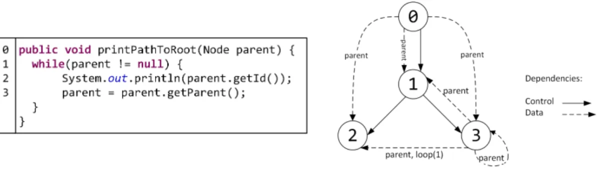
The core of our approach is built around the mapping of theProgram Dependence Graphs (PDGs) corresponding to duplicated code fragments. A PDG [FOW87] is a directed graph with multiple types of edges that represents dependencies between the elements of a program. A node in a PDG represents a statement of a function or a control predicate, and an edge represents control or data flow dependences between the nodes. Acontrol dependence edge denotes that the execution of the
statement at the end point of the edge depends on the control conditions of the control predicate statement (e.g.,if, for) at the start point of the edge. Adata dependence edge is always labeled with a variablev and it denotes that the statement at the end point of the edge is using the value of v, which has been modified by the statement at the start point of the edge. If the data dependence is carried through a loop nodel, then it is considered as aloop-carried dependence. Figure 6 shows an example code fragment and its corresponding PDG. In this example, node 0 represents the “method entry” node. There is a control dependence from the entry node to the loop (Node 1) and control dependences from Node 1 to all nodes that are directly contained by the loop (Node 2 and Node 3). There are data dependences from the entry node to all other nodes due to the variable parent. The other dependences are also due to the variableparent, sinceparent is defined in Node 3 and are used by Node 1, Node 2 and Node 3 because of the loop.
Figure 6: An example for PDG
Ottenstein and Ottenstein [OO84] mention PDG as an internal program representation which plays a major role in the system design. They suggest PDG as an effective tool in calculating program complexity metrics. Another main application of PDG is slicing [WRW03]. Slicing is the abstraction of program statements which affects the value of a variable in the code. The computation of slices is mostly used in debugging applications. PDG makes an ideal tool for constructing program slices. Horwitz and Reps [HR92] use PDGs in program differencing (finding differences between two programs) and program integration (integrating differences in one program onto another similar program). Software inspection is another area proposed by Walkinshaw et al. [WRW03] where PDGs can be used.
2.2
PDG-based Mapping Techniques
Komondoor and Horwitz [KH01] use Program Dependence Graphs(PDGs) and Program Slicing to find isomorphic Program Dependence Subgraphs that represent code clones. The main advantage of this approach is that it can detect non-contiguous clones (i.e., clones with gaps), clones in which matching statements have been re-ordered, and clones that are intertwined with each other. In their approach, two PDG nodes are matched if the corresponding statements or predicates are syntactically identical (i.e., their AST representation has the same structure) allowing only for differences in variable names and literal values. For each pair of matching nodes,backward slicing is performed in addition to forward slicing for matching predicates to construct a pair of isomorphic subgraphs (clones). A backward slice consists of all program points that affect a given point in the program whereas a forward slice consists of all program points that are affected by a given point in the program. The subsumed clone pairs are removed and the clone pairs are combined into larger groups wherever possible. Their method was implemented in a tool which finds duplicated code fragments in C programs and displays them to the programmer.
Krinke [Kri01] developed a method to identify code clones by computing the maximal similar subgraphs in fine-grained PDGs induced by k-limited paths starting from a pair of vertices. The method uses a fine-grained PDG (a specialization of the traditional PDG), in which there are special nodes for expressions, variable definitions, function calls etc. and special edges between expression components. In order to reduce the complexity of the algorithm, he considers only a subset of vertices (i.e., predicate vertices) as starting points, and restricts the maximum length of the explored paths using ak-limit. One important limitation of this proposal is that the running time of the algorithm increases tremendously as k-limit increases. Also, many duplicated results are calculated again because the algorithm generates maximal similar graphs for every pair of predicate nodes. Another limitation is that the use of k-limit may lead to an incomplete solution (i.e., the selected k-limit is insufficient for detecting all possible matching vertices). Using only predicate nodes as starting vertices is also a drawback since it can result in not finding some clones. The proposed technique cannot guarantee an optimal result since it is ak-limited technique.
Shepherd et al. [SGP04] implemented an automated aspect mining technique exploiting the Program Dependence Graph and Abstract Syntax Tree representations of a program. The proposed method identifies initial refactoring candidates using a control-based comparison which is inspired by the algorithms [Kri01] and [KH01] and then filters out the undesirable refactoring candidates based on data dependence information. They use a source level PDG in which nodes that correspond to the same source line number are collapsed into a single node and the duplicate edges are avoided from or to the subsuming nodes. The mapping of the code fragments is perfomed by matching control dependence subgraphs of each PDG starting from the method entry nodes. The limitation of this approach is that since the algorithm starts from the method entry nodes, it will fail to match the control dependence subgraphs nested in different levels. An example case is when the control dependence subgraph of one method is directly nested under the method entry node and the matching control dependence subgraph of the other method is not directly nested under the method entry node. They consider all possible combinations of PDG nodes at the same level by breadth first traversal of the control dependence subgraphs of each PDG(i.e., when a single node can be mapped to multiple nodes), but they do not provide a consistent search space because of the extensive pruning performed for reducing the overhead of the algorithm.
Even though PDG-based code clone detection techniques have the advantage of finding non-contiguous code clones, they are time consuming compared to other techniques. Higo and Kusumoto [HK11] discuss PDG specializations and some heuristics for enhancing PDG-based code clone de-tection, thus improving Komondoor’s technique [KH01]. The specializations are more specifically:
1. they introduced new edges called execution-next links, thereby expanding the range of program slicing in order to improve the ability to detect contiguous code, and
2. they merged multiple consecutive directly-connected equivalent nodes based on certain condi-tions thereby avoiding many node pairs as slice points resulting in false positives. This is done in order to reduce the computational cost of identifying isomorphic subgraphs.
The heuristics include two-way slicing (both backward and forward slicing), removing unnecessary slice points and neglecting small methods. They implemented the proposed technique in a tool called
Scorpio and investigated the effectiveness of each specialization and heuristic.
The common limitation of all aforementioned techniques is that they do not explore the entire search space of possible solutions and therefore they may return a non-optimal solution. The afore-mentioned techniques always select one match for each node, essentially exploring only a single path of the entire search tree. In addition, the applied node matching process allows only for differences in variable names and literal values, thus missing potential node matches that would lead to a better solution.
Speicher and Bremm [SB12] view the problem of software code clone removal as a process of stepwise unification of Type-3 clone instances using their Program Dependence Graph representa-tions. They suggested additional data dependencies by taking into account the method invocations and object aliases that affect the state of an object. The PDGs of the clone candidates are com-pared and the nodes are matched depending on the refactorings that are considered. For example, in RENAME refactoring, the statements with different names of local variables, parameters, fields and methods are mapped, while inREORDER PARAMETERS refactoring, method signatures that differ just in the order of parameters are mapped. Along with the many other techniques suggested by them in accomplishing refactoring, they suggest that differences in expression operators can be parameterized using lambda expressions (a feature introduced in Java 8). The process of statement unification allows for differences in the identifiers of local variables, parameters, fields, and method calls, differences in literals, differences in the types of declared objects, and finally, differences in the order of parameters in method calls.
Liu et al. [LCHY06] developed a software plagiarism detection tool called GPLAG. They support that the PDG structures of the original and the plagiarized code remain invariant since the PDGs encode the program logic. Their technique exploits this invariance property of PDGs to find pla-giarism through relaxed subgraph isomorphism testing, i.e., by checking if a PDG is γ-isomorphic to another, where γ is a relaxation parameter. In order to make the algorithm scalable to large programs, they prune the search space (i.e., they reduce the number of PDG pairs to be checked) by applying some filters. Even though they are able to detect five kinds of plagiarism disguises such as
‘Format alteration’, ‘Identifier renaming’, ‘Statement reordering’,‘Control replacement’ and ‘Code insertion’, the lossy filter applied to prune the search space may falsely exclude some interesting PDG pairs.
2.3
AST-based Mapping Techniques
Fluri et al. [FWPG07] describe an approach to extract the fine-grained changes that occur across different versions of a program. Their method is based on the tree alignment algorithm proposed by Chawathe et al. [CRGMW96], which takes as input two trees and produces a minimum edit script that can transform one tree into the other. They extended the original algorithm by applying the bigram string similarity measure for the matching of leaf nodes, and an enhanced subtree similarity criterion that takes into account the similarity of the nested nodes for the matching of control predicate structures. A limitation of the proposed approach is that string-based similarity matching is not resilient to extensive renaming of identifiers. In addition, the best match approach applied for leaf level nodes may match reoccurring statements that are not at the same position in the method body.
Cottrell et al. [CWD08] present an approach to help developers integrate reusable source code. Their algorithm takes as input two ASTs and tries to produce the best correspondences between the nodes. It applies a bottom-up comparison starting from leaf nodes (e.g., identifiers, types) and moving up to non-leaf nodes. The leaf identifiers are compared by means of the longest common substring measure. Non-leaf nodes are compared recursively taking into account the similarity of their children. The correspondences above a threshold value are finally used to identify the terms to be copied or transformed and integrated with the target system. A limitation is that the approach is only semi-automated, since user intervention is required to resolve the conflicts when multiple matches are found. Additionally, it tries to find a best fit in a greedy manner, which may lead to a non-optimal solution for the entire problem.
2.4
Clone Refactoring Techniques
Balazinska et al. [BMD+00] focus on the extraction of code clone differences, perform advanced code
clone analysis and provide the programmer with the information relevant to take a decision on the actual refactoring to be performed. Their technique to compare code fragments is based on the Dynamic Pattern Matching algorithm proposed by Kontogiannis et al. [KDM+96]. The proposed
algorithm aligns syntactically unstructured entities and finds an optimal distance between the two code fragments. The optimal distance is the minimum number of tokens to be inserted, deleted or substituted to transform one code fragment into another. However, this overall distance cannot be guaranteed as minimal as it tries to find optimal values at node level without considering the hierarchical structural differences at a higher level. The differences are expressed as programming language entities easily understandable by a programmer. This is done by projecting the tokens forming the differences onto the corresponding AST elements. The differences are also categorized based on the role in refactoring. The categories are:
1. superficial differences such as names of local variables which do not affect the behavior of methods
2. differences which affect the signature of methods: return value, access modifiers, thrown ex-ceptions etc.
3. differences affecting the types of parameters
4. all other differences.
The distinction among the differences helps the programmers to make the right decision regarding refactoring. As part of the proposed approach, they implemented an automatic refactoring process which transforms code clones using the design patterns Strategy and Template Method [GHJV95]. Higo et al. [HKI08] proposed a set of metrics to suggest different refactoring opportunities such as extract method refactoring and pull-up method refactoring in order to remove the software clones. The proposed method was implemented in a tool called ARIES which builds the ASTs of code clones detected using an existing code clone detection tool called CCFinder [KKI02]. A minimum token
length was used as the threshold in finding the refactoring oriented code clones. Some metric values were measured for these code clones which represent whether or not each of the code clones can be easily merged and how to merge them. It is up to the users to choose if refactoring should be performed. The following information is analyzed to characterize the clone sets:
1. how dispersed the code clones are across the class hierarchy and
2. the coupling between the code clone and its surrounding code in terms of the number of referenced and assigned variables within the clones.
The above values were used to represent the possibility of different refactoring patterns such asPull Up Method,Form Template Method etc. A small-scale case study was performed on the open source project Ant, and they concluded that the proposed method can efficiently merge code clones.
Choi et al. [CYI+11] performed an industrial case study and concluded that clone sets extracted by combining multiple clone metrics constitute better refactoring opportunities than clone sets ex-tracted by individual clone metrics. These metrics include the average length of token sequences of code clones within a clone set, ratio of length of the non-repeated token sequences to the length of the whole token sequences of code clones within a clone set, and the size of the code clone set. The analysis was performed on the clone sets detected by CCFinder [KKI02]. The effectiveness of their method was studied by conducting a case study on an industrial software. In this case study, they asked a software developer to fill out a questionnaire based on a list of selected code clones. The survey results were used as a basis to conclude that the developer found the clone sets detected by combining higher clone metrics as more desirable for refactoring. The survey conducted was very minimal as the survey included very small number of clone sets and was conducted on a single system and got feedback from one developer.
Tairas and Gray [TG12] developed an Eclipse plugin called CeDAR with the objective to unify the code clone maintenance activities by bridging the gap between the clone detection tools and the process of refactoring. They also extended the Eclipse refactoring engine to enable the processing of more types of differences among duplicated code fragments, such as differences in field accesses, and method calls without arguments, in addition to the differences in local variable identifiers which
is supported by Eclipse refactoring engine. They managed to parse the output results from five clone detection tools and they were presented to the developer using their plugin, so that the user can attempt to refactor the clones within the Eclipse IDE. They performed an evaluation on Type-2 clones detected in 9 open-source projects using Deckard [JMSG07] clone detection tool, which revealed that the aforementioned enhancements in the matching of duplicated code increased the percentage of refactorable clones from 10.6% to 18.7%. As future work, they mentioned the inclusion of more parameterized differences (e.g., local variable identifiers replaced with method calls) and the support for additional types of refactorings of clones belonging to different classes.
Hotta et al. [HHK12] built upon the method proposed by Juillerat and Hirsbrunner [JH07], to refactor Type-3 clones by applying Form Template Method. Form Template Method is one of the refactoring patterns proposed by Fowler et al. [Fow99]. This pattern targets similar methods existing in derived classes that inherit the same parent class. The code clones found by this method can be pulled up into the base class as a common process. Figure 7 shows an example of application of Form Template Method [Fow99]. The two classes ResidentialSite and LifelineSite inherit from the parent class Site. The methods namedgetBillableAmount()in both child classes are similar to each other. Through Form Template Method, the common code fragments are pulled up into the base class and the unique code fragments in each method are extracted as new methods,getBase() and getTax().
(a) Before
⇒
(b) After Figure 7: An example of application of Form Template Method
The technique proposed by Hotta et al. detects isomorphic subgraphs in the PDGs of two similar methods, which are considered to be the clone pair. Their PDG-based detection technique
can detect code clones containing different order of statements, and different implementation styles such as differences in for and while loops. The proposed method suggests program statements that can be merged into the base class as the common process and the program statements that should remain in the derived classes as the unique processes.
Bian et al. [BKSM13] presented a semantic-preserving amorphous procedure extraction algorithm (SPAPE) to extract the near-miss cloned code fragments (Type-2 and Type-3 code clones). The algorithm analyzes the two PDGs of the clone code fragments and uses a set of amorphous transfor-mation rules to make the cloned code statements suitable for extraction. The transfortransfor-mations are applied in order to replicate predicate statements and partition loop structures. In addition, the dif-fering statements are identified and combined by inserting control variables and control statements. Finally, the clone sequences are extracted into a procedure. Currently, SPAPE supports procedural code written in the C programming language.
Goto et al. [GYI+13] proposed a method which detects ‘Extract Method’ candidate sets among
a pair of similar Java methods and are ranked according to cohesiveness. AST differencing is used to detect the syntactic differences between the input pair of methods and slice-based cohesion metrics such asTightness,Coverage andOverlap are used to rank the obtained refactoring candidates. The proposed approach is developed to help those programmers who need to refactor similar methods into cohesive methods. A case study performed by the authors indicated that the refactorings suggested by their method helped to increase two out of the three slice based cohesion metrics.
Chapter 3
Clone Unification
The proposed technique for the unification of clones in order to refactor them comprises three major steps as follows:
1. Control Structure Matching: The control structure of the code fragments is extracted into trees called Control Dependence Trees and they are matched for identifying potential refactoring candidates as well as to determine valid clone regions.
2. Program Dependence Graph Matching: The output of this phase is an optimal match of the PDGs corresponding to the matched subtrees from the previous step.
3. Checking Preconditions: A check is done against a set of predetermined conditions to ensure that the code behavior is preserved and to determine whether it is safe to refactor.
An overview of the process flow is shown in Figure 8. The input to the process can be either clone fragments detected by a clone detection tool or two methods manually selected by the programmer. The technique determines the Control Dependence Trees (CDTs) of the input code fragments. The matching pairs of subtrees of the CDTs are found and passed to the PDG mapping phase. The PDGs undergo the mapping process where two nodes are matched if they are within the control structure of the matched CDT pairs. The output of the PDG mapping phase is a set of mapped and unmapped statements with the differences between the mapped statements. The differences and the unmapped statements are checked against preconditions to evaluate if the mapped statements can be refactored.
The section 3.1 in this chapter explains the statement matching process used in the proposed technique and the rest of the chapter discusses each of the above steps in detail.
3.1
Statement Matching
This section deals with our statement matching process. Statement matching is a core functionality used throughout our algorithms in order to examine if two statements are compatible and to find the exact differences between them, if any. Two statements are said to be compatible if they can be matched by parameterizing their differences.
3.1.1
Abstract Syntax Tree
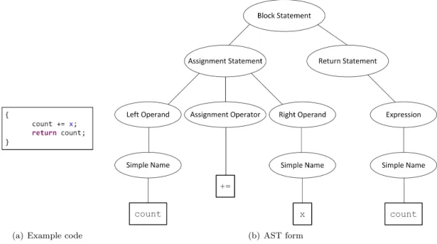
In our statement matching process, we analyze the Abstract Syntax Tree (AST) structure of the statements. AST is a tree-like representation of the source code. Each Java source file is represented as a CompilationUnit, which is the root of the corresponding AST tree. Each node of the Abstract Syntax Tree denotes a construct in the code and provides specific information about the object it represents. For example, a method is represented as aMethodDeclaration AST node and any string that is not a Java keyword is represented as a SimpleNamenode. An example of an Abstract Syntax Tree is given in the Figure 9.
(a) Example code (b) AST form
Figure 9: A block of source code and the corresponding Abstract Syntax Tree
3.1.2
AST Matching
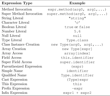
The clone unification method in this thesis is basically a process of matching the PDGs of two methods. Each AST statement forms a PDG node where AST statement is the AST repre-sentation of a program statement. There are many different types of AST statements such as ContinueStatement, WhileStatement etc. We consider two PDG nodes as compatible, if they correspond to the same AST statement type and have a matching AST structure. However, a high degree of freedom is required in the matching of expressions within the statements in order to make flexible the unification of duplicated code with non-trivial differences. In the past, Tairas and Gray [TG12] extended the Eclipse IDE refactoring engine for duplicated code, which supports only the parameterization of differences in local variable identifiers, by additionally allowing the matching of differences in field accesses, string literals, and method calls without arguments. But in general, the differences are not always trivial as mentioned before in Chapter 1. In our AST matching implementation, we have significantly increased the number of expression types that could be parameterized, and additionally we allow the matching of different types of expressions. Table 1 contains the complete list of supported expression types and shows the degree of freedom we allow in matching two expressions. Any expression type in that list can be replaced with any other expression
type as long as both expressions return the same class/primitive type or types being subclasses of a common superclass (excludingjava.lang.Object, becauseObjectis the implicit superclass of every Java class, unless it explicitly extends another class).
Table 1: Supported Expression Types In AST Matching
Expression Type Example
Method Invocation expr.method(arg0, arg1,...) Super Method Invocation super.method(arg0, arg1,...) String Literal "string"
Character Literal ‘c’
Boolean Literal trueor false
Number Literal 5.6
Null Literal null
Type Literal Type.class
Class Instance Creation new Type(arg0, arg1,...)
Array Creation new Type[expr]
Array Access array[index]
Field Access this.identifier
Super Field Access super.identifier Parenthesized Expression (expr)
Simple Name identifier
Qualified Name Type.identifier
Cast Expression (Type)expr
This Expression this
Prefix Expression -expr
Infix Expression expr1 + expr2
*we also support the matching of an assignment expression, where
the left-hand side is a field access, e.g.,field = value, with the corresponding setter method invocation, e.g.,setField(value).
3.1.3
Implementation Details
Our AST matching algorithm has been implemented by extending theASTMatchersuperclass pro-vided in Eclipse JDT framework. The default implementation of ASTMatcherprovided by Eclipse computes whether two ASTs subtrees are structurally isomorphic. Our implementation overrides some of the match methods in order to define more relaxed subtree matchers. For example, in the case of control predicate nodes (e.g.,if,forstatements), the AST structure contains the con-ditional expression(s) and their bodies. Our overridden matchimplementation will compare only their conditional expression(s) and ignores the bodies, because the statements inside them will be subsequently compared if the control predicate statements are found compatible. In addition, the
AST matching algorithm returns a list of differences detected between the matched AST state-ments. These differences are essential for the procedure of optimization and the examination of preconditions, which will be explained in the next chapter.
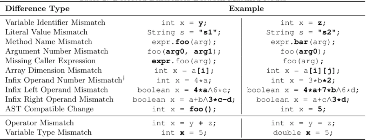
Table 2 shows the difference types which are reported by our AST matching algorithm. The last two difference types, namely operator and variable type mismatches are not parameterized in our approach. However, lambda expressions (a feature of Java 8.0) can be used to unify operator mismatches, whereas the concept of generics can be applied to unify variable type mismatches. Though these two scenarios are not explored as part of this thesis, they can be used to advance the refactoring technique in the future. In the cases where a difference refers to a property of a primary expression (e.g., method name mismatch, argument number mismatch, missing caller expression), the entire primary expression (e.g., method invocation) should be parameterized.
Table 2: Detected Differences Between Matched Nodes
Difference Type Example
Variable Identifier Mismatch int x = y; int x = z;
Literal Value Mismatch String s = "s1"; String s = "s2";
Method Name Mismatch expr.foo(arg); expr.bar(arg);
Argument Number Mismatch foo(arg0, arg1); foo(arg0);
Missing Caller Expression expr.foo(arg); foo(arg);
Array Dimension Mismatch int x = a[i]; int x = a[i][j];
Infix Operand Number Mismatch† int x = 4*a; int x = 3*b*2;
Infix Left Operand Mismatch boolean x = 4*a∧6*c; boolean x = 4*a+7*b∧6*d;
Infix Right Operand Mismatch boolean x = a+b∧3*c-d; boolean x = a+c∧3*d;
AST Compatible Change int x = foo(); int x = 5;
Operator Mismatch int x = y + z; int x = y - z;
Variable Type Mismatch int x = 5; double x = 5;
†
Infix operand number mismatch refers to the number of extended operands. The extended operands is the preferred way of representing deeply nested expressions of the form L op R op R2 op R3... where the same operator appears between all the operands (the most common case being lengthy string concatenation expressions).
An example of our AST matching process is explained below. Let’s assume we have the state-ments shown in Figure 10 along with their AST representations. Our AST matching algorithm applies the steps as described in Table 3.
(a) Statement 1
(b) Statement 2
Table 3: Execution Steps In AST Matching Process
Step AST Node 1 AST Node 2 Action
1 result=2+first+3*second+2; result=first+4*second; Both are ExpressionStatements. Proceeding to match expressions. 2 result=2+first+3*second+2 result=first+4*second
Both are Assignments. Proceeding to match assignment operators.
3 = =
Both operators are same. Proceeding to match left hand side operands.
4 result result
No difference. Proceeding to match right hand side operands.
5 2+first+3*second+2 first+4*second
Both are Infix Expressions. Proceeding to match extended operands. 6
No extended operands. Proceeding to match left hand side operands.
7 2+first+3*second first
No matching AST structure. The first node is Infix Expression and the second node is Simple Name. Reporting INFIX LEFT OPERAND MISMATCH. However, they have the same type. Proceeding to match right hand side operands.
8 2 4*second
No matching AST structure. The first node is Number Literal and the second node is Infix Expression.
Reporting INFIX RIGHT OPERAND MISMATCH. However, they have the same type.
9
Both left hand side and right hand side operands did not match. Decision to
parameterize the entire infix expression.
3.2
Control Structure Matching
Control structure matching is the first major step in our clone unification algorithm. We have made the assumption that in order to extract pieces of duplicated code, they should have exactly the same structure of control. In other words, only complete AST-subtrees having the same structure
can be valid candidates for refactoring. To achieve this condition, we find the common control structures within the input clones. Finding control structures also helps us to tackle the challenge of getting valid clone regions as mentioned in Section 1.5. Experience has shown that text-based and token-based clone detection tools may return invalid clone regions [TG12, HKI08]. The control structure matching phase addresses this problem, since the control structures always form valid clone regions. Another advantage of comparing control structures beforehand is that it helps to improve the performance of PDG matching algorithm. The PDG matching process is subject to the combinatorial explosion effect since there would be many nodes to be matched. As the number of possible matches for the nodes increases, the width of the search tree grows rapidly as a result of the numerous combinatorial considerations to be explored. The risk of combinatorial explosion is reduced by taking advantage of the control dependence structure of the two compared PDGs and matching them first. By taking advantage of the control structure, we can avoid the unnecessary comparison of nodes nested at different levels. This is explained in Section 3.3.
The proposed technique is able to process two different forms of input:
1. Two code fragments within the body of the same method, or different methods, reported as clones by a clone detection tool.
2. Two method definitions considered to be duplicated or containing duplicate code fragments, usually selected by the user.
Since control structure essentially forms a tree, we can conclude that our input constitutes two trees corresponding to the control structure of the input clones. Tree matching algorithms are used to find the largest common, non-overlapping subtrees within the input trees. In the book “Algorithms on Trees and Graphs”, Valiente [Val02] describes bottom-up and top-down algorithms for finding the common subtrees. A hybrid algorithm which combines both bottom-up and top-down approaches is developed for our matching technique.
3.2.1
Control Dependence Tree Representation
The control dependence structure of an input clone is represented as a Control Dependence Tree (CDT). More specifically, we first build the Control Dependence Tree of each input clone. A CDT has the same structure as theControl Dependence Graph (CDG) [FOW87] with the only difference being that it includes only the control predicate nodes of the PDG, while a CDG contains all nodes of the PDG. Basically, a CDT represents the nesting of control structure of the code fragment.
For example, consider the two candidate methods for clone refactoring given in Figure 11 and the corresponding Control Dependence Trees in Figure 12. The code example is taken from the book “Refactoring: Improving the Design of Existing Code” [Fow99]. The CDTs of the methods do not form isomorphic trees. Two trees are said to beisomorphic when there is a bijective correspondence between their node sets which preserves the structure of the trees. The formal definition of tree isomorphism [Val02] is given below.
Two unordered trees T1 = (V1,E1) andT2 = (V2,E2) areisomorphic, if there is a bijection M
⊆V1 ×V2 such that (root[T1],root[T2])∈ M and the following condition
• parent[v] = parent[w]for all nonroots v ∈V1 and w∈ V2 with (v,w) ∈M
is satisfied.
In this thesis, we are interested in finding isomorphic subtrees within the CDTs of the clone fragments, where the bijective correspondence between two nodes exists when they are AST com-patible. AST compatibility is checked using the techniques mentioned in Section 3.1. We have to find the largest possible common subtrees [Val02] in the CDTs of the clones to find valid refactoring opportunities. In the cases, where the input CDTs are isomorphic, the input pair of CDTs itself forms a refactoring opportunity.
Figure 12: The Control Dependence Trees for the code fragments of Figure 11
3.2.2
Algorithm
Our goal is to find isomorphic CDTs within the duplicated code fragments. In other words, we have to find the largest common subtrees [Val02] in the input CDTs. We construct the control dependence subtrees corresponding to each code fragment or the entire method. An algorithm is developed that takes as input two CDTs (CDT1,CDT2) and finds all non-overlappinglargest common
subtrees [Val02] within the CDTs. Each resulting subtree match will be further investigated as a separate clone refactoring opportunity. In the previous example shown in Figure 12, the largest common subtrees will be {2,5,13}and {8,11,19}where (2,8), (5,11)and (13,19)are the AST compatible node pairs. The numbers are used only for representing each statement in the example and have no relevance to the implementation of the process.
Step 1: Selecting leaf nodes
Initially, we start in a bottom up fashion i.e., we start from the leaf nodes of the input Control Dependence Trees. We collect from the two CDTs all leaf nodes, which either do not have siblings, or all of their siblings are also leaf nodes. This is done for improving the efficiency of the algorithm
by avoiding repeated analysis of the nodes. The reason is explained with an example as follows. In the beginning, we do not need to consider the leaf nodes which have any non-leaf siblings, since they will be explored in the later recursions of the algorithm when we consider their siblings which are non-leaf nodes. For example, in the Control Dependence Tree shown in Figure 12(b), the leaf nodes are11,19 and 23. But only the nodes11 and19 are considered initially, as 23would be visited later as part of the siblings of 8.
Step 2: Making match pairs of leaf nodes
The next step is to extract all matching pairs i.e., AST compatible nodes (the compatibility is checked using the statement matching process in Section 3.1.2), among the collected leaf node sets from the two CDTs. Each extracted leaf node pair is represented as (nodei,nodej), wherenodeiand nodej are leaf nodes of CDT1 and CDT2 respectively. In the CDT pair in Figure 12, the possible
matchings of leaf nodes are(5,11),(5,19),(13,11)and(13,19). We keep the best matching node pairs (i.e., node pairs with minimum number of differences) and therefore the extracted leaf node pairs are(5,11)and(13,19)(these are exactly matched node pairs with no differences).
Step 3: Filtering match pairs of leaf nodes
Instead of processing every extracted leaf node pairs, a filtering (i.e., removing some node pairs based on certain conditions as explained below) is done as another step to improve the efficiency of the algorithm. When sibling node pairs exist in the extracted leaf node pairs, only one of them is taken for further processing, since the common subtrees found from any of the sibling node pairs using Algorithm 1 will exactly be the same. In other words, when (nodei,nodej) and (nodex,nodey)
exist in the extracted leaf node pairs, andnodexand nodey are siblings ofnodei andnodej
respec-tively, (nodei,nodej) and (nodex,nodey) are called sibling pairs. Only one of the sibling pairs, say
(nodei,nodej) is added to the filtered leaf node pairs list for further processing. In the example given
Step 4: Forming common subtree pairs
Each leaf node pair (nodei,nodej) in the filtered leaf node pairs list obtained from Step 3, is given as
input to Algorithm 1, which returns a subtree match (a pair ofisomorphic subtrees) as a solution.
1 FunctionbottomUpMatch(nodePair,solution)
Data: nodePairrepresents a pair of matching CDT nodes (nodei, nodej)
Result: solutioncontains a set of CDT node pairs representing a complete subtree match
2 appendnodePairto solution 3 siblingsi←nodePair.nodei.siblings 4 siblingsj ←nodePair.nodej.siblings 5 matchedSiblings ←∅
6 tempSolution←∅
7 foreachsiblingi∈siblingsi do 8 foreachsiblingj∈siblingsj do
9 if compatibleAST(siblingi,siblingj) and 10 not alreadyMatched(siblingj) then 11 pair←(siblingi,siblingj) 12 pairs←topDownMatch(pair)
13 if exactlyPairedSubtrees(pairs)then 14 add pair→matchedSiblings 15 appendpairstotempSolution
16 break// first-match
17 end if
18 end if
19 end foreach 20 end foreach
21 if |matchedSiblings|= |siblingsi| =|siblingsj|then 22 appendtempSolutiontosolution
23 parenti ←nodePair.nodei.parent 24 parentj ←nodePair.nodej.parent
25 if compatibleAST(parenti,parentj) then 26 pair←(parenti,parentj)
27 bottomUpMatch(pair,solution)
28 end if
29 end if 30 end
Algorithm 1:Recursive function returning the maximum exactly paired subtree match starting from a given node pair.
Explanation of the Algorithm
The algorithm first compares sibling nodes of the nodes in the input node pair to find matching sibling pairs. The siblings are matched by checking if they have compatible AST structure (line 9) as explained in Section 3.1. For each matching sibling pair it performs a top-down tree match (line 12) and examines if the resulting subtree match is “exactly paired” (line13). Two subtrees
are considered as exactly paired if there is aone-to-one correspondence between their nodes (i.e., a bijection). In set theory, there is a bijection from setX to setY when every element ofX is paired with exactly one element ofY, and every element ofY is paired with exactly one element ofX. If all matching sibling pairs lead to exactly paired top-down subtree matches, then the parent nodes of the node pair given as input are visited. Finally, if the parent nodes match (line25), then Algorithm 1 is recursively executed with the new parent node pair as input. The proposed algorithm essentially applies a combination of bottom-up and top-down tree matching techniques [Val02] and guarantees that the returned subtree match will be exactly paired. The algorithm is designed to return only exactly paired subtree matches in order to avoid inconsistencies or gaps in the control dependence structure of the matched subtrees. CDT subtrees without inconsistencies or gaps in their control structure make better candidates for clone refactoring, since the possibility of having unmatched statements is lower.
3.2.3
Working Example of
bottomUpMatch
Algorithm
In the example given in Figure 12,(5,11)is given as input tobottomUpMatchalgorithm. (5,11) is added to solution. Siblings of5and11form a pair(13,19), since13and19are AST compatible. As13and 19have no children, they will satisfy the condition of “exactly paired top-down subtree matches”. (13,19)is added to the solution and parents of 5and 11 are visited since all siblings are covered. The parents of 5and 11 are AST compatible and they form a nodePair (2,8). The nodePair (2,8) is input to the recursive call of bottomUpMatchalgorithm. The nodePair (2,8) is appended to the solution. Since no sibling pairs are found for (2,8) and the counts of siblings of nodes 2 and 8 do not match, algorithm does not continue. The resulting solution is therefore
{(2,8),(5,11),(13,19)}.
3.3
PDG Matching
In the previous section, we described the algorithm that extracts isomorphic subtrees from the CDTs of the clones given as input. The obtained isomorphic subtrees are used in matching the subgraphs
of Program Dependence Graphs such that only the non-control nodes within the matched control structures need to be analyzed as the control nodes are already matched. This avoids the exhaustive comparison of all nodes, since the algorithm will try to match only those nodes nested under matched control structures. In this section, an approach for an “optimal” mapping of the PDG subgraphs corresponding to the extracted CDT subtree match pairs is presented.
3.3.1
Advantages of PDG Matching
Since clones may be identical (Type-1) or may be with some differences (Type-2 and Type-3), PDG is the most appropriate representation of the clone instances to identify the statements that are equal or unifiable. This is because of two reasons:
1. PDG can reduce the ambiguity of statement matching, since statement similarity can be as-sessed not only based on textual or AST-structure similarity, but also based on the matching of incoming/outgoing control and data dependencies (Chapter 2).
2. PDG can be used to determine whether the unmatched statements between the clones (i.e., statements in gaps) can be moved before or after the execution of the duplicated code by examining whether this move alters the original data dependencies of the graph [TC11].
3.3.2
Why do we need the PDG Mapping to be Improved?
With each statement considered as a node in PDG, one thing to remember is that there can be more than one common subgraph with the same number of nodes for the given PDGs. Therefore, we need to find an optimal mapping of PDG subgraphs. It is defined as a problem in which we find the common subgraph that satisfies the following conditions:
1. It has the maximum number of matched nodes.
<