Worcester Polytechnic Institute
Digital WPI
Major Qualifying Projects (All Years)
Major Qualifying Projects
April 2017
Smart Home Energy Controller
Andrew William Reyburn
Worcester Polytechnic Institute
Eric Philip Meier
Worcester Polytechnic Institute
Follow this and additional works at:
https://digitalcommons.wpi.edu/mqp-all
This Unrestricted is brought to you for free and open access by the Major Qualifying Projects at Digital WPI. It has been accepted for inclusion in Major Qualifying Projects (All Years) by an authorized administrator of Digital WPI. For more information, please [email protected].
Repository Citation
Smart Home Energy Controller
April 12, 2017
A Major Qualifying Project Report Submitted
to the faculty of WORCESTER POLYTECHNIC INSTITUTE
In partial fulfillment of the requirements for the
Degree of Bachelor of Science
An MQP by:
Andrew Reyburn, [email protected]
Eric Meier, [email protected]
Submitted to:
Professor Fred Looft, ECE and SE
This Major Qualifying Project is submitted in partial fulfillment of the degree requirements of Worcester Polytechnic Institute. The views and opinions expressed herein are those of the authors and do not
Abstract
The purpose of this project was to design a prototype device that could address the two main issues the team identified with existing residential solar systems: specifically, the inability to use solar power when the grid is offline and the inability to dynamically allocate power in a reconfigurable manner, depending on the power available from a solar PV system. The team researched solar system topologies and components, used a systems engineering approach to design a potential solution, and then built and tested a proof of concept device referred to as smart home energy controller. This report details the current state of solar PV system architectures, identifies current PV system design limitations, and explains the team’s proposed solutions. The group also addresses the final PV system designs and the technical challenges encountered with the technologies used in the prototype test setup.
Acknowledgements
We would like to acknowledge our advisor Professor Looft in his guidance and encouragement for us to keep trying something new and pushing us to achieve our best. We would also like to acknowledge and thank Jim Dunn for his professional advice and help in this project. Without his insights, the team would have faced a much more difficult time in implementing the prototype.
Table of Contents
Table of Figures ... i
Table of Tables ... iii
1.0 Introduction ... 1 1.1 Introduction ... 1 1.2 Project Statement ... 3 1.3 Summary ... 3 2.0 Background ... 4 2.1 Introduction ... 4
2.2 System Coupling and Wiring ... 4
2.2.1 AC Solar System Coupling ... 4
2.2.2 DC Solar System Coupling ... 5
2.2.3 Split Phase Power ... 6
2.2.4 Home Grounding System ... 7
2.3 Solar Inverters for Grid Tie and Off-Grid ... 8
2.3.1 Introduction to Inverters... 8
2.3.2 Central Inverters ... 9
2.3.3 Microinverters ... 10
2.4 System Layouts for Hybrid Grid Tied Solar With Batteries ... 11
2.4.1 Hybrid Grid Tie System with Battery Backup ... 11
2.4.2 SMA Technologies Hybrid Grid Setup ... 13
2.4.3 SolarEdge ... 14
2.4.4 Schneider Electric ... 17
2.5 Batteries ... 19
2.5.1 ABB REACT Battery ... 19
2.5.2 Tesla Powerwall ... 20
2.6 Charge Controllers ... 22
2.6.1 Battery Charge Controllers ... 22
2.6.2 Solar Charge Controllers and MPPT ... 22
2.7 Automatic Transfer Switches ... 22
2.8 Islanding Detection Methods ... 26
2.9 Switching Transients ... 27
3.0 Problem Statement ... 30
3.1 Introduction ... 30
3.2 Problem Statement ... 30
3.2.1 Perform Background Research ... 31
4.0 System Concepts ... 32 4.1 Introduction ... 32 4.2 Stakeholder Analysis... 32 4.2.1 Stakeholders ... 32 4.2.2 System Needs ... 33 4.3 CONOPS ... 35
4.3.1 Expected Operational Environment ... 35
4.3.2 Use Cases ... 35
4.3.3 Gap Analysis ... 38
4.3.6 Design Needs ... 39
4.3.4 System Specifications ... 40
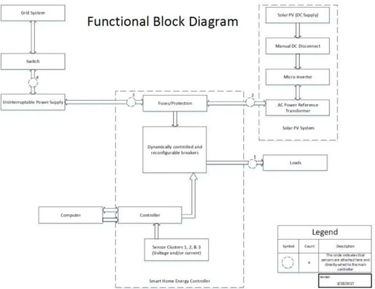
4.4 Final System Architecture ... 41
4.4.1 System Architecture ... 41
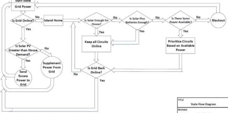
4.4.2 System Control Logic ... 43
4.5 Summary ... 44
5.0 Prototype Test System Design ... 45
5.1 Introduction ... 45
5.2 The Setup ... 45
5.2.1 Electronically Controlled Breakers ... 46
5.2.2 Pure Sine Wave UPS ... 46
5.2.3 Voltage Sensor ... 46
5.2.4 The Current Sensor ... 47
5.2.5 The Microinverter... 47
5.2.6 Microinverter Wiring ... 48
5.2.7 Arduino Mega Board ... 49
5.2.8 Microcontroller Wiring ... 49
5.2.9 Custom MOSFET Protoboard ... 51
5.3 System Testing Procedure... 51
5.4 Component Verification ... 54
5.4.2 Microinverter Testing ... 57
5.4.3 Voltage Sensor Testing ... 57
5.4.4 Microcontroller Verification ... 58
5.4.5 MOSFET Board Testing ... 59
6.0 Integrated System Testing and Results ... 60
6.1 Introduction ... 60
6.1 Microinverter Testing Results ... 60
6.2 UPS with Microinverter Testing Results ... 61
6.3 Solar Panel Testing Results... 63
6.4 Controller Testing Results ... 64
6.4.1 Current Sensor ... 64
6.4.2 Voltage Sensor ... 66
6.4.3 Microcontroller ... 67
6.5 Smart Home Energy Controller Test Results ... 68
6.6 Distortion Source Testing ... 68
6.6.1 Transformer Testing ... 68
6.6.2 Light Bulb Testing ... 69
6.7 Transient Testing ... 70
6.8 Results Summary ... 72
7.0 Conclusion ... 73
Appendices ... 74
Appendix A. Color Coded System Level Functional Block Diagram (Power) ... 74
Appendix B. Color Coded System Level Functional Block Diagram (Data) ... 75
Appendix C. Color Coded System Level Functional Block Diagram (Signals) ... 76
Appendix D. Zoomed in UPS Transfer Time ... 77
Appendix E. Simulation Oscillogram for Voltage Sensor ... 78
Appendix F. Linearity of Voltage Sensor ... 79
Appendix G. Wiring Diagram for BABRP1020 Breaker ... 80
Appendix H. Arduino Optimization Code ... 81
Appendix I. SolarEdge Single Phase Inverter SE3000A-US ... 87
Table of Figures
Figure 1. Solar PV Growth Predictions1 ... 1
Figure 2. Power Outages Due to Extreme Weather ... 2
Figure 3. AC Coupled System ... 5
Figure 4. DC Coupled Solar System ... 6
Figure 5. Utility Distribution Transformer and Split Phase Power ... 7
Figure 6. Home Grounding System ... 8
Figure 7. Inverter Waveform Outputs ... 9
Figure 8. Enphase M190 Microinverter ... 10
Figure 9. A Grid-tie System with Battery Backup ... 12
Figure 10. Sample SMA Grid-tie with Battery Backup Configuration ... 13
Figure 11. SolarEdge StorEdge Solutions ... 15
Figure 12. SolarEdge StorEdge Single Phase Inverter... 16
Figure 13. SolarEdge Wi-Fi Communication Solution... 16
Figure 14. Conext XW Hybrid Grid Tie System... 17
Figure 15. Schneider Electric Conext XW+ Solar Hybrid Inverter System ... 18
Figure 16. ABB REACT Battery and Inverter34 ... 19
Figure 17. Tesla Powerwall 2 ... 20
Figure 18. High Level Generator and Transfer Switch Setup ... 23
Figure 19. S&C Source Transfer Operating States ... 25
Figure 20. Impulse Transient ... 27
Figure 21. Oscillatory Transient ... 28
Figure 22. System Level Functional Block Diagram ... 41
Figure 23. State Flow Logic for Controller Algorithm ... 43
Figure 24. Main Test Bed Wiring Diagram ... 46
Figure 25. Custom AC Voltage Sensor Schematic ... 47
Figure 26. Solar System Power Wiring Diagram... 48
Figure 27. Arduino Mega Board ... 49
Figure 28. Microcontroller Diagram for Sensors and Electronic Breaker Controls... 50
Figure 29. Microcontroller Diagram Additional Electronic Breaker Controls ... 51
Figure 30. Mounted Test Setup ... 52
Figure 31. APC Back-Up UPS RS 1200 Main Waveform ... 55
Figure 32. APC Back-Up UPS RS 1200 Inverter Waveform ... 55
Figure 33. CyberPower UPS Grid to Battery Power Waveform ... 56
Figure 34. CyberPower UPS Battery to Grid Power Waveform ... 56
Figure 35. Voltage Sensor Readings ... 58
Figure 36. Microinverter Line Two (Blue) and AK (Yellow) Voltage Waveform ... 61
Figure 37. UPS and Microinverter On-Grid to Off-Grid Transition ... 62
Figure 38. Off-grid to On-grid Transition ... 63
Figure 39. Current vs Voltage Waveforms Pushing Power into Test Bed ... 64
Figure 40. Current Sensor Output Waveform with All Loads On ... 65
Figure 41. Distorted Current Sensor Waveform When Pushing Power into AK ... 65
Figure 42. Current Sensors Output Waveform - Mostly in Phase ... 66
Figure 44. Transformer fed by Function Generator, 10V Peak at 60Hz ... 68
Figure 45. Waveform Comparison - CFL in Blue, AK in Yellow ... 69
Figure 46. Waveform Comparison - Incandescent in Yellow, AK in Blue ... 69
Figure 47. On-Grid Voltage Sag Caused by Motor Operation ... 70
Figure 48. Off-Grid Voltage Sag Caused by Motor Operation ... 71
Figure 49. Off-Grid Voltage Sag Closeup Due to Motor Operation ... 71
Figure 50. Electronic Breaker Transient Testing - Breaker Closing and Restoring Power ... 72
Table of Tables
Table 1. Stakeholders and their Interests ... 32
Table 2. System Needs ... 34
Table 3. Use Case for Selecting Circuit Prioritization ... 36
Table 4. Use Case for Measuring Power Flows ... 37
Table 5. Use Case for Pressing the Emergency Stop Button ... 38
Table 6. Gap Analysis ... 38
Table 7. Design Needs ... 39
Table 8. Electrical Specifications ... 40
1.0 Introduction
1.1 Introduction
Recent data from the Solar Energy Industries Association (SEIA) shows an overwhelming surge in home solar installations.1 Figure 1 displays the yearly installed solar capacity from 2010 to the expected
installed capacity by 2021. The yearly installed capacity is divided into three categories: residential, non-residential, and utility. Residential solar capacity is indicated in green on the graph. The orange segment (or non-residential) is solar capacity installed on business or other non-residential sites. The final segment is utility solar in the form of utility scale solar power plants and is shown in blue. This data shows a rise in expected installed capacity, which introduces load balancing issues during power outages as solar power cannot be used during the outage. As yearly U.S. solar installations increase, coupled with increasing outages due to extreme weather events, there will be a rise in situations in which homeowners that have solar power will be unable to use their solar power.
Figure 1. Solar PV Growth Predictions1
1SEIA. (2016). Yearly U.S. Solar Installations [Online image].
In general, residential home solar systems are not independent of the grid as they require a constant grid connection to operate. If an outage occurs, the solar inverters used in the solar system must shut down almost immediately per utility regulations. The implications of this are that even if the solar power system is generating power it cannot be fed into the residential building in the event of a power outage. The back feeding of power into the grid is prohibited during an outage to avoid energizing distribution lines that line workers may be working on.
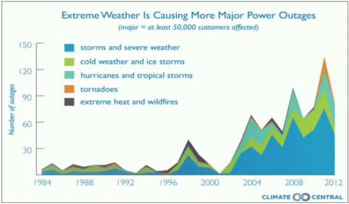
As climate change accelerates, increasing extreme weather events are causing more power outages. Figure 2 from Climate Central shows the number of outages affecting at least 50,000 customers or more from 1984 to 2012.2 The graph shows that the growth of major power outages events is
accelerating following the turn of century. The number of power outages from 2000 to 2013 have increased by 600% according to Inside Energy.3 These power outages currently cost American
households around $150 billion annually with each unplanned outage costing about $8,852 per minute on average.4 5 The $8,852 figure is based on a calculation that takes into account certain factors
resulting from no electricity such as: costs due to lost productivity, damaged pipes and equipment due to cold weather, flooded basements, and food spoilage.
Figure 2. Power Outages Due to Extreme Weather6
2 Kenward, A., & Raja, U. (2014). Blackout: Extreme Weather, Climate Change and Power Outages. Princeton: Climate
Central. Retrieved from http://www.climatecentral.org/news/weather-related-blackouts-doubled-since-2003-report-17281
3 Wirfs-Brock, J. (2014, August 18). Power Outages On The Rise Across The U.S. Retrieved from Inside Energy:
http://insideenergy.org/2014/08/18/power-outages-on-the-rise-across-the-u-s/
4Emerson. (2016, January 19). Emerson Network Power Study Says Unplanned Data Center Outages Cost Companies Nearly
$9,000 Per Minute. Retrieved from Vertiv: https://www.vertivco.com/en-us/about/newsroom/corporate-news/emerson-network-power-study-says-unplanned-data-center-outages-cost-companies-nearly-$9000-per-minute/
5 Kohler Generators. (2014, August 08). The Cost of Power Outage in the U.S. Retrieved from Kohler Generators:
http://www.kohlergenerators.com/common/pdf/RES_Infographic.pdf
6 Kenward, A., & Raja, U. (2014). Blackout: Extreme Weather, Climate Change and Power Outages. Princeton: Climate
1.2 Project Statement
The purpose of this project was to address the inability of residential solar systems to supply power to a house during a power outage by islanding a home and incorporating the ability to dynamically allocate available solar power. The goal of this project was to design and demonstrate a conceptual device that would enable homeowners to use their solar panels when a grid outage has occurred in a regulation compliant manner using dynamic power allocation. The objectives of this project were to: perform background research on solar systems, explore system architectures of existing solar systems, design the smart home energy controller, and create a small-scale demonstration of the prototype system design.
1.3 Summary
The problems that this project seeks to address are those caused by the increasing market penetration of residential solar systems and an increasing rate of power outages, during which a residential solar system cannot function. With a projected growth in expected installed solar capacity and in extreme weather events damaging the power system, residential solar systems should possess the ability to island a home and continue to provide power even when the main utility connection is offline. To enable these features for current residential solar systems, the team conducted background research on solar systems, designed the smart home energy controller, and performed testing and validation.
2.0 Background
2.1 Introduction
The background section provides a brief overview of the various technologies behind a residential solar system and those that are needed to build the smart home energy controller. The main focus of the research was to examine the technology incorporated in off-grid and hybrid solar systems to island a home with respect to the utility grid which is for a solar system to operate during a power outage. In addition to off-grid systems, on-grid system layouts and architectures are reviewed to study how current systems work and their limitations. The background research then delves into the individual components of a solar system. The three types of solar system configurations for residential solar are: grid tied solar, hybrid grid tied, and off-grid.
2.2 System Coupling and Wiring
2.2.1 AC Solar System Coupling
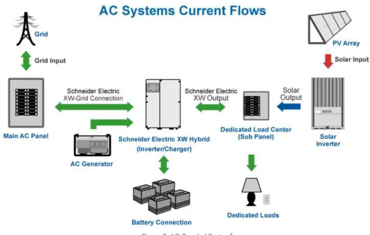
AC coupling is a solar interconnect topology in which a solar system and battery are connected on the AC side, rather than a direct DC connection from the solar panels to the battery, which would be a DC coupled system. In the AC coupled system, the output of the battery and solar panel is converted to AC with an inverter and then they are connected on a common AC line. The AC line then interfaces with the home’s load to supply power.
One of the challenges with an AC coupled system, as demonstrated in Figure 3, is that there are two inverters, one for the solar system and one for the battery. The system in Figure 3 is a retrofit that is designed to integrate with existing residential solar systems to provide battery backup capabilities. When the utility grid is lost in an AC coupled system, the battery inverter must perform two tasks: disconnect the home from the utility grid, and provide a reference waveform for the solar inverter. Without the reference waveform, the solar inverter will not work, and this feature is what dictates a manual system restart if the battery goes offline.7
7Lorenz, E. (2015, January). AC or DC Coupled - What? Retrieved from CivicSolar:
Figure 3. AC Coupled System8
2.2.2 DC Solar System Coupling
In a DC coupled solar system, batteries are connected to the PV panel’s DC output, which then connects to an inverter that then feeds AC power into a home. An example of a DC coupled system can be found in Figure 4 as well as Figure 10. The solar panel’s output is maximized via maximum power point tracking (MPPT) that then feeds the battery charge controller and then the loads through the inverter. Maximum power point tracking is a feature of most inverters or power optimizers that changes the DC voltage so that on the V-I power curve, the solar system will output at the point of maximum power. See Appendix J for more information on how MPPT works. When utility grid power is lost, the inverter can then transfer the load to a secondary sub-panel ensuring that power still flows while disconnecting from the grid.9 DC coupled systems are generally less expensive because they do not
require a second inverter. An example of a battery in a DC coupled system would be the Tesla Powerwall in Section 2.5.2, which is connects directly to the solar panel output and the panels are used to charge the Powerwall directly.
8Schneider Electric. (2016). AC Systems Current Flows [Online image].
Retrieved March 19, 2017 from http://www.amerescosolar.com/sites/default/files/ac-battery-backup-diagram.jpg
9 Lorenz, E. (2015, January). AC or DC Coupled - What? Retrieved from CivicSolar:
Figure 4. DC Coupled Solar System10
2.2.3 Split Phase Power
In the typical home, the utility company will provide split phase power to the house from a center tap transformer which is supplied by tapping a single-phase distribution line. This is accomplished by using a center tap transformer to create two phases for a home, which is demonstrated in Figure 5. Starting at the distribution transformer on the pole, a single phase is split to produce 120/240V AC split phase power. Figure 5 shows a center-tap transformer in which the voltage across two output lines is 240V AC. The center of the output transformer winding is tapped to serve as a zero-volt reference for each of the output lines and when an output line is referenced to the center tap or neutral, the voltage is 120V AC (the split phases). The center tap or neutral is generally non-current carrying. These two lines 120V lines are 180 degrees out of phase with respect to each other, and are used to create 240V for large appliances in a house.11
10Wind & Sun. (2017). Grid Connect System with Battery Storage. Retrieved from Wind and Sun:
http://www.windandsun.co.uk/information/types-of-system/grid-connect-system-with-battery-storage.aspx
11Sharma, V. (2012, August 01). 120 / 240 VAC Single Split Phase & Multi-Wire Branch Circuits. Retrieved from
SamlexAmerica: http://www.samlexamerica.com/support/documents/WhitePaper-120240VACSingleSplitPhaseandMultiWireBranchCircuits.pdf
Figure 5. Utility Distribution Transformer and Split Phase Power12
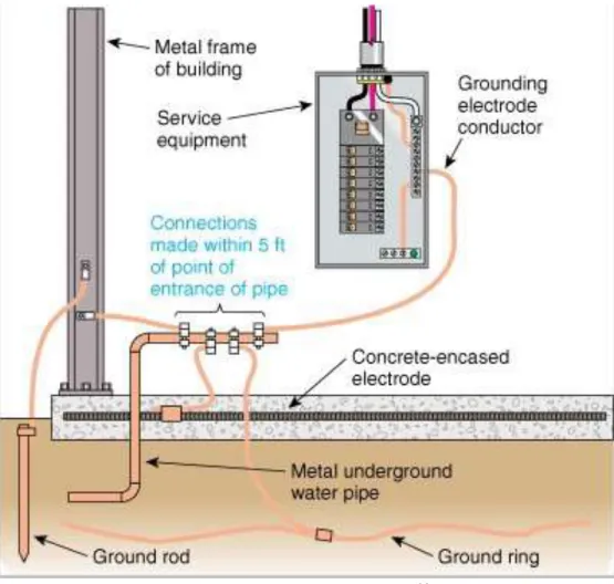
2.2.4 Home Grounding System
The purpose of the home grounding system illustrated in Figure 6 helps to prevent electrical shocks to electricians and the homeowner. Article 250 of the National Electric Code (NEC) specifies the requirements for a grounding system. The earth grounding system in a home connects the breaker box to water pipes and then to a ground rod or ring as a noncurrent carrying system.13 The ground
connection from the breaker box may also connect directly to a ground rod or ground ring as well. In the event of a fault or lightning surge, current is shunted to the earth through the ground system.
12Haynes, G. (n.d.). Inside household distribution transformer. Retrieved 2017, from See inside main breaker box:
http://waterheatertimer.org/See-inside-main-breaker-box.html
13 Biesterveld, Jim. (2011). GROUNDING AND BONDING NATIONAL ELECTRICAL CODE ARTICLE 250 [PowerPoint
Figure 6. Home Grounding System14
2.3 Solar Inverters for Grid Tie and Off-Grid
2.3.1 Introduction to Inverters
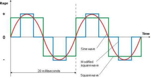
A power inverter converts DC to AC and is used in a solar system to convert the DC output of solar panels to AC for use in a home. In principle, any DC to AC inverter uses transistors to control the flow of DC power through the use of pulse width modulation (PWM) by switching the transistors in the inverter on or off to create the desired waveform. Inverters can output a variety of different waveforms, such as a square wave, modified sine wave, or a pure sine wave as shown in Figure 7.
14Hester, D. (2013, 02 07). Concrete encased Electrodes- UFER everybody. Retrieved from North Central Washinton Home
Figure 7. Inverter Waveform Outputs15
For a simple inverter, its output is a square wave or modified sine wave, but by using different filters and digital signal processing techniques, the square wave can be filtered into a sine wave.16 An
H-bridge can be used to create a single AC phase, which is then passed through a transformer if higher output voltage is needed. Filters can then be used to further refine the output sine wave to produce a pure sine wave.17
2.3.2 Central Inverters
There are two main types of inverters for solar PV systems, distributed inverters (such as microinverters which are attached to each individual solar panel) and central inverters, with a single inverter for all the solar panels in the system. Central inverters in a solar system application are DC/AC converters that can convert all the available power from a home’s solar system and output split phase 120V or single phase 240V into a home’s breaker box, matching the grid’s voltage waveform. Both central inverters and microinverters need to match their output voltage waveform to the grid’s because if it is off by more than a few degrees, power cancellation occurs and eventual system failure would occur. The grid also provides the primary reference frequency for inverter operation as the inverter must match the grid’s frequency. Central inverters typically range from 3-10KW, but can come in a variety of sizes. MPPT is standard in most central inverters, as is anti-islanding protection. Anti-islanding protection is required in central inverters to prevent them from back feeding power into the distribution lines during a power outage to avoid injuring line workers. For off-grid applications, central inverters do not need anti-islanding protections as they would prevent proper inverter operation. There are also limitations to the efficiency of MPPT on central inverters as the MPPT is functioning across the whole solar system and not just an individual PV module. For an example of a central inverter and sample specifications, see Appendix I.
15Nasir, S. Z. (2012, November 5). Pure Sine Wave Inverter Design With Code. Retrieved from The Engineering Projects:
http://www.theengineeringprojects.com/2012/11/pure-sine-wave-inter-design-with-code.html
16 Grabianowski, E. (2009, February 10). How DC/AC Power Inverters Work. Retrieved from HowStuffWorks.com:
http://electronics.howstuffworks.com/gadgets/automotive/dc-ac-power-inverter2.htm
17 Worden, J., & Zuercher-Martinson, M. (2009, May). How Inverters Work. Retrieved from SolarPro:
2.3.3 Microinverters
Microinverters are DC to AC inverters that are designed to attach to each individual solar PV panel and are meant to be connected to adjacent microinverters in a solar system. They allow for a decentralized system of solar inverters rather than a single central inverter. This allows each inverter to have a lower power rating and system failure can be avoided if an inverter fails. When a PV modules is shaded, each microinverter will perform MPPT limited to their individual module leading to more optimized power production from each module, improving the overall system power output versus a central inverter. Even without shading effects, microinverters optimize the solar system power output as much as 2-3% more when compared to a central inverter with string optimizers.18
While microinverters provide several advantages, they are generally harder to replace and repair.19
When a central inverter fails, the inverter can be easily repaired or replaced by a technician because it is relatively easy to access. However, when a microinverter fails, the solar panel must be removed from its mounting and the inverter must be replaced, creating additional work and cost. Since the microinverter must be mounted outdoors behind the solar panel, they also experience higher rates of failure due to weather conditions and heat generated by the solar panels. In addition, they do not have uniform rates of failure.
Figure 8. Enphase M190 Microinverter20
Microinverters (such as the one shown in Figure 8) need an AC grid as an input reference, otherwise they cannot operate as all the microinverters need to follow a reference frequency.21 The Enphase
M190 Microinverter in Figure 7 has a power output of 190W at both 208V or 240V with a nominal frequency of 60Hz with a frequency range of 59.3Hz to 60.5Hz.
18 Jacobson, N., Donovan, M., & Forrest, J. (2013). Enphase Energy. PV Evolution Labs. Retrieved from
https://enphase.com/sites/default/files/PVEL_Study-on-EE-vs-SolarEdge.pdf
19Energysage. (n.d.). Advantages & disadvantages of micro-inverters & power optimizers. Retrieved from Energysage:
https://www.energysage.com/solar/101/microinverters-power-optimizers-advantages-disadvantages/
20 Enertek Supply. (2011). Enphase M190 - Ontario FIT. Retrieved from Enertek:
http://www.enerteksupply.com/enphase-m190.html
21 Enphase Energy. (2014, January 17). AC Coupling of Enphase Microinverters to Battery Based Systems. Retrieved from
2.4 System Layouts for Hybrid Grid Tied Solar With Batteries
Hybrid grid tie solar systems are those that are connected to a utility grid and can function during a power outage by disconnecting from the utility grid. A hybrid inverter can function with multiple power inputs from solar systems and batteries, which allows for energy to be stored and used at various times.22 The battery however is optional in the system and is not required. A hybrid inverter eliminates
the need for a second inverter for the battery system and the major advantage of hybrid systems is that they can provide a battery backup for backup power.
2.4.1 Hybrid Grid Tie System with Battery Backup
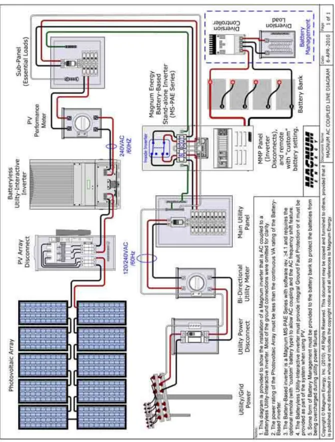
Grid tie systems with battery backup or generator backup capabilities can be implemented in several different ways. Figure 9 shows one method of configuring a hybrid grid tie system with battery backup in which the solar system supplies a central solar inverter. The solar inverter is then connected to a subpanel of essential loads which can supply preselected circuits in the home. A battery and divisionary load is connected to the battery inverter panel which has disconnects in order to island the home during a power outage. The battery inverter supplies the lost AC waveform in order to keep the solar system online.
The sub-panel serves as the breaker box for the “essential” circuits connected to a battery bank or an attached generator. When installing the system, the homeowner must decide which circuits they want powered by the sub-panel when the electrician installs the system. The battery inverter acts as a charge controller which controls the charging of the battery bank and the power flow to and from the batteries in the event of an outage to the sub-panel. If the current draw from the battery bank is too high, the charge controller will shut down to protect the batteries and wires from overheating past their thermal limits.
The battery inverter can include a battery monitor and load balancer, depending on the manufacturer, and the inverter plugs connects to the battery bank. The battery bank then helps provide power to the AC sub-panel when the solar PV panels are insufficient to meet demand. The inverter also connects to the main breaker panel and can serve as a conduit for the power from the solar system to the rest of the house when the grid is online. To measure power flows in both directions, a bidirectional meter is used.23
22Zipp, K. (2015, January 14). How are hybrid inverters used in solar projects? Retrieved from Solar Power World:
http://www.solarpowerworldonline.com/2015/01/hybrid-inverters-used-solar-projects/
23 SEIA. (2012). Net Metering. Retrieved from Solar Energy Industries Association:
Figure 9. A Grid-tie System with Battery Backup24
24Magnum Energy. (2010, May 1). MAGNUM AC COUPLED LINE DIAGRAM. Retrieved from Magnum Energy:
2.4.2 SMA Technologies Hybrid Grid Setup
SMA Solar Technology manufactures on-grid and off-grid solar system solutions designed to upgrade residential home energy systems and function without a utility connection. For hybrid grid solutions, a sample system wiring diagram for an AC coupled system is shown in Figure 10. The central points of the system are the PV inverter and the Sunny Island battery inverter. Connections to two main sources are offered in the hybrid grid tie system. These main sources are a diesel generator or a utility grid connection can be used to supply the home. A transfer switch is used to switch between these two sources as necessary. However, in off-grid mode, the utility grid connection is not available and power would be provided by the batteries, solar system, and optionally a generator.
Figure 10. Sample SMA Grid-tie with Battery Backup Configuration25
25SMA Solar Technology. (2014, October 28). Wiring Diagram Solar System Off Grid. Retrieved from SMA:
2.4.3 SolarEdge
SolarEdge manufactures a family of products within its StorEdge hybrid solar system that can provide power during an outage using battery based storage.26 The SolarEdge inverter acts as the central
controller connecting a solar system, battery pack, loads, and meters. SolarEdge utilizes a DC coupled system for improved efficiency and to provide power in the case of grid failure. An example of a typical SolarEdge system with a solar inverter and battery backup can be seen in Figure 11.
The StorEdge system is designed to be compatible with a Tesla Powerwall or LG Chem battery to provide power during an outage. The control system also allows for the powering of preselected circuits during an outage or demand response in addition to load shaving during non-outages. Measurements are conducted with the SolarEdge Electricity Meter with on-grid installations to provide information on whether to store electricity or export to the utility. The meter will also help measure how much energy is left in the battery and help reduce general electricity consumption.
The power optimizers in the system help to optimize the power output of the solar panels using MPPT. They also monitor the performance of the solar system and relay that information back to the homeowner.27 One of the differences between the SolarEdge system and the SMA Technologies
system is that the SolarEdge system uses a DC connection between the battery and solar system versus the SMA system which the connects the batteries through a second inverter on the AC side with AC coupling.
2.4.3.1 The SolarEdge Inverter
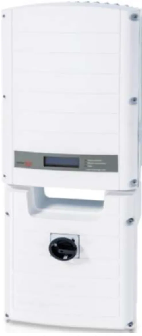
SolarEdge manufactures a single phase solar inverter for use with residential and commercial solar installations. The SolarEdge single phase StorEdge hybrid inverter in Figure 12 features two input connections, battery and PV and can operate in backup mode. The frequency tolerances for the inverter are 60Hz nominal, plus or minus 5Hz.In both normal operating mode and backup mode, the nominal rated power output is 5000VA at 220/230V AC. The SolarEdge inverter features internet connectivity via RS485, ethernet, or wirelessly with a ZigBee in Figure 13 or Wi-Fi.28
26 SolarEdge. (2016). StorEdge™ Products for On-grid Applications & Backup Power. Retrieved from SolarEdge:
http://www.solaredge.com/us/products/storedge#/
27 SolarEdge. (2016). Power Optimizer. Retrieved from SolarEdge: http://www.solaredge.com/us/products/power-optimizer#/ 28 SolarEdge. (2017, March). SolarEdge Single Phase StorEdge Inverter. Retrieved from StorEdge:
Figure 11. SolarEdge StorEdge Solutions29
29SolarEdge. (2017). The SolarEdge StorEdge Solution. Retrieved from SolarEdge:
Figure 12. SolarEdge StorEdge Single Phase Inverter
Figure 13. SolarEdge Wi-Fi Communication Solution30
30SolarEdge. (2016). SolarEdge Home Gateway Kit. Retrieved from SolarEdge:
2.4.4 Schneider Electric
Schneider Electric manufactures a residential hybrid grid-tie solar system with a battery backup shown in Figure 14. In the hybrid DC coupled system the Conext XW+ inverter serves as the central junction point accepting feeds from the grid (main AC panel), and solar and batteries while distributing power to the AC subpanel.31 During an outage, power is provided to the AC subpanel, which is isolated from the
main AC panel. Hybrid grid tie systems such as the one in Figure 14 are also capable of load peak shaving and other utility interactive mechanisms that can help make adopting solar PV easier for the grid system. Like Figure 11, Figure 14 follows an almost identical architecture.
Figure 14. Conext XW Hybrid Grid Tie System32
31Schneider Electric. (2016, October 17). Grid-tie, off-grid solar and backup power solutions. Retrieved from Schneider
Electric: http://cdn.solar.schneider-electric.com/wp-content/uploads/2014/04/Grid-tie-Off-grid-Solar-and-Backup-Power-Solutions-Brochure2.pdf
32 Schneider Electric. (2014). Residential, self consumption. Retrieved from Schneider Electric:
2.4.4.1 Schneider Electric Inverter
The Schneider Electric Conext XW+ 120/240V Inverter supports single or three phase systems from 7kW to 102kW with a multiple inverter array system for both off-grid and on-grid applications. Generators and the grid are potential input connections along with a supporting battery system. The output voltage is 120/240V with a +/- 3% tolerance and the output frequency range is 59.4 to 60.4 Hz with a +/- 0.05Hz tolerance. For off-grid support, frequency control is offered, along with other features such as prioritizing power sources, load shaving, and selling excess power to the grid. The Schneider Electric Inverter can be seen in Figure 15.
Figure 15. Schneider Electric Conext XW+ Solar Hybrid Inverter System33
33Schneider Electric. (2015). Conext XW hybrid inverter/charger. Retrieved from Schneider Electric:
2.5 Batteries
2.5.1 ABB REACT Battery
The ABB REACT in Figure 16 is a combined solar inverter and 2 kWh battery. It is a 230V, 50 Hz single phase system with additional MPPTs for solar systems designed for European use. To measure the production of the solar system, energy meters are integrated into the system along with an additional load manager function. For overvoltage protection, there are varistors, which will act as an open circuit during an overvoltage event. For remote monitoring, the ABB REACT is equipped with a Wi-Fi connection and a user interface consisting of a mobile app, user display panel, or web page.34 During
an outage, the battery can support an AC output with an automatic or manual restart. The length of time the battery will last depends on the active loads.
Figure 16. ABB REACT Battery and Inverter34
34 ABB. (2016, November 22). REACT-3.6/4.6-TL 3.6 to 4.6 kW. Retrieved from ABB PV + Storage:
2.5.2 Tesla Powerwall
The Tesla Powerwall 2 battery, shown in Figure 17, has a 13.5kWh capacity and can provide 7kW peak power and 5kW continuously and features an integrated inverter.35 The Powerwall can both serve as a
backup to the grid in the event of an outage and power the entire home or select circuits in conjunction with solar panels. As a storage system, it can store power from the solar system for use at night or to use off-grid. The Tesla Powerwall will charge during the day when home energy demand is low, and solar production is high. The stored power can be used during peak consumption hours which are not the peak production hours. The solar system will still need to be net metered to measure solar system production for the utility.
Figure 17. Tesla Powerwall 236
35Tesla. (2017). Powerwall. Retrieved from Tesla: https://www.tesla.com/powerwall 36 Tesla. (2017). Powerwall [Online image]. Retrieved March 5, 2017 from
The Powerwall connects to the solar system and can either be AC or DC coupled. The batteries only draw or produce power when either: instructed to by a controller via a communications port or when the Powerwall senses the home loads are greater than power generation. The integrated inverter then converts DC power to AC power for use by the home with an energy meter to measure solar production and home power usage. To power the home during an outage, a backup panel is needed to switch the power supply from the grid to the solar panels and battery. The roundtrip efficiency for the Tesla Powerwall is 89% for AC coupling and 91.8% for DC coupling, making it an efficient battery storage system.37
37Lambert, F. (2016, October 28). Tesla Powerwall 2 is a game changer in home energy storage: 14 kWh w/ inverter for
$5,500. Retrieved from Electrek: https://electrek.co/2016/10/28/tesla-powerwall-2-game-changer-in-home-energy-storage-14-kwh-inverter-5500/
2.6 Charge Controllers
2.6.1 Battery Charge Controllers
Battery charge controllers are devices used to prevent a battery from overcharging and prevent unintentional discharge current through the attached solar panels at night. At night, the panels will draw some current from the battery if sufficient protection is not built into the battery charge controller. The night time system losses can be prevented with a transistor or relay switch that opens at night. Preventing the batteries from overcharging is the main purpose of any battery charge controller because overcharging can damage the battery and eventually cause it to catch fire.38
2.6.2 Solar Charge Controllers and MPPT
MPPT charge controllers control the output voltage and current of solar panels to maximize the amount of power delivered under varying conditions.39 MPPT helps to improve the solar system performance
and can be applied to the system as a whole or to individual panels. Varying conditions can include cloud cover shading the panels, tree branches casting shadows on panels, or the changing angle of the sun. When a panel is under these varying conditions a MPPT controller will output a voltage with a variable current delivering maximum power instead of operating at the standard panel voltage output.40
As a day progresses, the irradiance and other factors change, causing the solar panels to produce less power, requiring the MPPT to alter voltage levels to maximize power production. The MPPT acts as a DC to DC converter to modulate the solar panel array output which reduces the losses from the panel.41
2.7 Automatic Transfer Switches
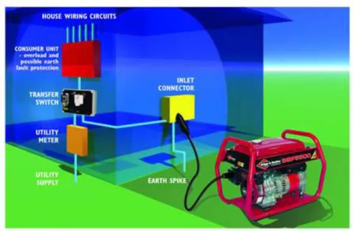
An automatic transfer switch (ATS) as illustrated in Figure 18 allows for selected grid-tie circuits to switch from main power to a secondary power source (solar or generator) in the event of a grid outage. The ATS (black box in Figure 18) has two inputs, the utility grid and a generator (or equivalent source). The transfer switch is connected to both the home circuits via the breaker box and the generator while offering a central connection point to the utility. The ATS is required by the National Electric Code (NEC) for a standby generator that automatically switches on during an outage, and it must be installed next to the breaker panel in a home. The switch transfers the power source from the utility grid-tie to an alternative source to ensure both sources cannot be active at the same time to prevent power from flowing back into the grid during an outage and injuring line workers.
38Dankoff, W. (1999). What is a Charge Controller? Retrieved from Blue Sky Energy:
http://www.blueskyenergyinc.com/reviews/article/what_is_a_charge_controller
39 Northern Arizona Wind & Sun. (2013). All About Maximum Power Point Tracking (MPPT) Solar Charge Controllers.
Retrieved from Northern Arizona Wind & Sun: https://www.solar-electric.com/mppt-solar-charge-controllers.html/
40 Cullen, R. (2009, March 25). What is Maximum Power Point Tracking (MPPT) and How Does it Work? Retrieved from Blue
Sky Energy: http://www.blueskyenergyinc.com/uploads/pdf/BSE_What_is_MPPT.pdf
41 Bas, L. (2011, March). How do MPPT charge controllers work? Retrieved from CivicSolar:
Both manual and automatic switches exist with automatic switches allowing for an uninterruptible power supply (UPS) by automatically switching to generator power during an outage.42 An ATS uses a motor
operator to switch the breakers in the event of an outage, and it is protected with a separate fuse.
Figure 18. High Level Generator and Transfer Switch Setup43
To operate, an ATS must first detect an outage or power quality issue to bring the standby generator online. Once the generator is running with a stable voltage and frequency, the load is shifted from the utility power to the generator. The circuits powered by the ATS are chosen in advance by the homeowner when an electrician installs the ATS. The ATS ensures that the sources cannot be paralleled in operation, preventing power feedback into the grid.
To detect an outage or power quality issue, both voltage and frequency are usually monitored with set points enabled so if a certain voltage drop or rise is detected; the power source is transferred to a standby generator. When an outage is detected, the transfer switch is programmed with a variable time delay to ensure that the outage or power quality loss is not momentary and allows the standby generator time to come online. The variable time delay is usually between zero to six seconds.
Fault detection on the incoming power line may be achieved with overcurrent relays or current transformers. To protect the ATS, surge protection is needed both before and after the ATS as the switch action can generate transients, which can damage equipment past the ATS. 44
42 Honda. (2012). Connecting your generator to your home. Retrieved from Honda Power Equipment:
http://powerequipment.honda.com/generators/connecting-a-generator-to-your-home
43 Jefferson Energy Cooperative. (2014). Using Generators. Retrieved from Jefferson Energy Cooperative:
http://www.jec.coop/content/using-generators
44 Moraff, P. (2016). ATS (AUTOMATIC TRANSFER SWITCH) APPLICATION. Retrieved from MCG Surge Protection:
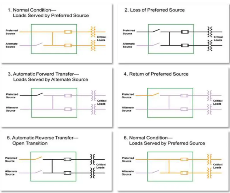
To avoid paralleling sources, the backup source is disconnected before switching back to the primary source. There is also an overcurrent sensor on the alternate source in the event the alternate source experiences a fault.45 The operating states for a sample ATS is shown in Figure 19.
The first state in Figure 19 shows that the critical load is supplied by the preferred source (such as a utility connection). The alternate source (such as a battery bank) is connected to the open switch, which prevents it from being able to turn on when not needed. When the power of the preferred source is lost, the switch connecting it to the load is opened in state two. During state three, the alternate source switch is closed to deliver power to the critical load. State four occurs once the power is turned back on and the utility grid is restored. The next step in state five is to open the alternate source switch, disconnecting both sources to avoid paralleling the sources. Finally, the preferred source switch is closed, connecting the utility grid back to the critical load (the home).
45S&C Electric Company. (2014). Solutions for Automatic Source-Transfer. Retrieved from S&C Electric Company:
Figure 19. S&C Source Transfer Operating States46
46S&C Electric Company. (2014). Solutions for Automatic Source-Transfer. Retrieved from S&C Electric Company:
2.8 Islanding Detection Methods
Current solar grid tie systems must have anti-islanding protection built in per UL standard 1741. There are several different methods for detecting a grid outage such as transient detection for voltage, frequency, or current.47 The purpose of these outage detection methods or “islanding detection
methods” is to force the solar inverter to immediately shut down during an outage.
When abnormal grid conditions are detected, an isolator switch (potentially an ATS) needs to fully disconnect the house from the grid, satisfying the NEC and UL 1741 standard. Inverter generators may need low-voltage-ride-through (LVRT) and frequency-ride-through (FRT) when switching to island mode or even as the utility grid is failing as specified by the utility. In the low-voltage-ride-through mode, when the grid voltage rises or falls beyond its limits for a short amount of time, the inverter must stay connected to help maintain grid stability. Inversely, LVRT can occur with high voltages as well, and in Hawaii, the inverter only shuts down when the voltage passes 120% or 113%-120% for more than 0.9 seconds, whichever comes first. FRT is similar to the voltage-ride-through in which the inverter must stay online during short-term frequency excursions beyond nominal.48 Depending on utility
requirements, this feature may be necessary to assist grid stability during frequency excursions by forcing the solar generation to remain online. The inverter will then monitor utility line voltage or frequency to detect a reactivation of the grid and then reconnect. The solar inverter can only reconnect and synchronize the frequency to the utility grid to begin power production five minutes after the grid comes back online per utility regulations.49
To synchronize with the utility grid, an inverter can generate an AC output waveform using PWM to match the utility grid waveform. Combined with active sensing, the inverter will continually match and adjust its frequency to the utility grid. A phase-lock loop (PLL) can then be used to match the inverters waveform output with the utility grid, helping to further synchronize the PWM waveform. A relay circuit will then break the connection with the utility grid in the event of a detected outage or fault.50 In order to
detect frequency excursions past the phase lock loop reference, a zero-crossing detector is used which drives an output when the input passes the reference signal. The PLL serves as the reference signal input.51
47De Rooij, D. (2015, July 16). Islanding: what is it and how to protect from it? Retrieved from SinoVoltaics:
http://sinovoltaics.com/learning-center/system-design/islanding-protection/
48 Dyke, J. (2015, May 5). Hawaiian grid requirements explained: interim ride through. Retrieved from SMA:
http://www.smainverted.com/hawaiian-grid-requirements-explained-interim-ride-through/
49 Greacen, C., Engel, R., & Quetchenbach, T. (2013). A Guidebook on Grid Interconnection and Islanded Operation of
Mini-Grid Power Systems Up to 200 kW. Berkeley: Lawrence Berkeley National Laboratory. Retrieved from
http://www.cleanenergyministerial.org/Portals/2/pdfs/A_Guidebook_for_Minigrids-SERC_LBNL_March_2013.pdf
50 Evanczuk, S. (2015, June 25). Anti-Islanding and Smart Grid Protection. Retrieved from Digi-Key:
https://www.digikey.com/en/articles/techzone/2015/jun/anti-islanding-and-smart-grid-protection
51 Advanced Linear Devices. (2005). Zero Crossing Detector. Retrieved from Advanced Linear Devices:
Grid-tie inverters are generally not designed to provide AC power if the grid power is not present. To synchronize the inverter output to the utility grid, a phase-locked oscillator is used and during an outage, the phase-locked oscillator drifts out of tolerance signaling an outage event. If there is an outage, the phase-locked loop frequency will drift to zero as only the inverter is supplying power to the grid. Therefore, a limit is set, at which point when the phase-locked loop frequency drifts past the limit, the inverter shuts off. Once the outage ends, the PLL and the utility grid synchronize and solar power production resumes.52
2.9 Switching Transients
In an off-grid home electrical system, the home grid will have to contend with various switching transients that would otherwise be absorbed by the utility grid. These switching transients occur when an inductive or capacitive load is switched on or off, causing power quality degradation. The transients may be either a voltage or current transient within two categories. The first category is an impulsive transient as shown in Figure 20, which is a sudden surge in power that is very damaging. In addition to transients from switched inductive/capacitive loads, lightning strikes will also cause an impulsive transient.
Figure 20. Impulse Transient53
The other form of transients are oscillatory transients as demonstrated in Figure 21. These are caused by capacitive or inductive loads turning off and generally last a single cycle, which changes the steady state waveform. Surge protective devices and UPS’s both serve as a protection against these types of transients along with a line reactor.53
52Meares, L. (2012, August 7). Product How-To: Solar power anti-islanding and control. Retrieved from EDN Network:
http://www.edn.com/design/systems-design/4391907/Product-How-To--Solar-power-anti-islanding-and-control
53 Seymour, J. (2012, May 4). The Seven Types of Power Problems. Retrieved from Schneider Electric:
Figure 21. Oscillatory Transient54
In a home, transients will be primarily generated through inductive switching, with capacitive switching being uncommon in a home and are typically only at the utility level or at large industrial facilities. The interactions however between the inductive and capacitive loads can cause oscillations as well, resulting in transients which can increase the voltage spike.55 Current transients are typically caused by
motors starting, and will cause little damage if the circuit breaker or fuse is not tripped. Voltage transients can be caused by switching or resonance conditions, or by factors related to the electrical distribution system. Voltage sags that are one cycle or less will have little effect on the home electrical system and smaller voltage dips will also not have much impact if they do not last long. In addition, most electrical equipment can withstand a range of input voltages, so a slight deviation from 120V will not be critical.56
54Seymour, J. (2012, May 4). The Seven Types of Power Problems. Retrieved from Schneider Electric:
http://www.apc.com/salestools/VAVR-5WKLPK/VAVR-5WKLPK_R1_EN.pdf?sdirect=true
55 Davis, E., Kooiman, N., & Viswanathan, K. (2014). Data Assessment for Electrical Surge Protection Devices. Quincy: The
Fire Protection Research Foundation. Retrieved from http://www.nemasurge.org/wp-content/uploads/2015/01/Surge-Protective-Devices-for-Residential-Applications-Phase-1-Final.pdf
56 Generac. (2011, January 26). Transients in mission critical facilities. Retrieved from Generac Industrial Power:
2.10 Summary
There are many different grid tie solutions and configurations out on the market, but they all have common elements and similar system layout configurations. Solar inverters are the backbone of any solar PV installation because they are responsible for detecting a grid outage and determining whether to shut down or if backup power is available, switch to backup power. Automatic transfer switches are needed to disconnect the home to either a battery backup or standby generator. There are many different ways to configure battery backup storage. Batteries can be placed between the solar PV and inverter or separately attached to a secondary breaker panel with a charge controller that serves as the backup circuits. Microinverters are similar to central inverters except that each microinverter attaches to each panel, and are daisy chained together. Microinverters also have MPPT built into them already, which eliminates the need for system level MPPT tracking. Transients are sudden voltage or current spikes (or oscillations) that can occur when switching on inductive or capacitive loads. They can cause damage to electrical equipment if not properly mitigated.
3.0 Problem Statement
3.1 Introduction
Currently, if a homeowner wants to install solar panels to reduce their electric bill, they will often go with a grid-tied solar system. In the event of a power outage, a homeowner is currently not allowed to run their inverter in order to prevent line back-feed, and therefore cannot use their solar energy, despite power being readily available. To address this issue, one approach is to install a hybrid grid-tie system. These systems offer a grid-tie with a battery backup, but only to preselected circuits in a separate breaker box, which cannot be changed unless an electrician rewires a breaker box. Hybrid grid-tie solutions still do not address the desire to dynamically allocate available power to the homeowner’s circuits without the need for an electrician.
3.2 Problem Statement
The purpose of this project was to prototype a device known as a “Smart Home Energy Controller” that would allow residential solar panels to operate during a power outage. Specific design objectives for the prototype included the following.
1. Accept power from a variety of sources such as solar or batteries.
2. Dynamically allocate available power to different circuits based on alternative power available during a power outage using electronically controlled breakers and an optimization algorithm. 3. Be able to island the home after an outage has occurred and keep solar system online.
The specific goals of this project were to research, design, simulate, and build selected components for the smart home energy controller. To accomplish these goals, the following objectives were addressed:
1. Perform background research on all relevant devices and systems that will connect and directly interact with the smart home energy controller.
2. Explore system architectures best suited to achieve the project goals based on existing systems.
3. Design a small-scale version of the smart home controller, and a test bed to test the system. 4. Test selected components.
3.2.1 Perform Background Research
The team researched the types of solar systems on the market as well as how hybrid grid tied solar systems work. In order to design the smart home energy controller, the team needed to understand how it would interface with existing systems. The background research was critical to understand the limitations of existing technology in order to create solutions for these limitations.
3.2.2 Explore System Architectures
Similar to background research, the team needed to understand how solar systems and their subcomponents are architected. This included knowing how solar inverters communicate with other devices, and what components (like automatic transfer switches, voltage sensors) are inside each device in a solar system. This understanding of how components are designed and architected gave the team ideas for how to architect the smart home energy controller.
3.2.3 Design the Smart Home Energy Controller
The team applied engineering practices and system engineering principles to design a functional smart home energy controller that could island itself from the main utility grid and dynamically control its loads. To accomplish this, the background research was utilized along with the various stakeholder and design needs, uses cases, and a defined operational environment. While creating the design, schematics were generated and implemented into the overall test bed. The required system logic was developed into a flow diagram and a system context diagram was created in order to understand all the inputs, outputs, and functionality required. After this, the team went through design reviews for each component until a prototype of the smart home energy controller was fully designed.
3.2.4 Test Selected Components
The team tested certain off the shelf components that would be integrated into the smart home energy controller, such as the electronic breakers, transfer switches, and sensors. The purpose of this testing was to confirm that these devices would function as designed inside the smart home energy controller.
4.0 System Concepts
4.1 Introduction
In order to design and architect the smart home energy controller, the team took a systems engineering approach to tackling the design aspect, the stakeholders, and all the relevant analysis and processes necessary to produce a high quality and well thought out design.
4.2 Stakeholder Analysis
4.2.1 Stakeholders
Stakeholders are the parties that will be impacted by or have an interest in the design and implementation of the smart home energy controller. Each stakeholder in Table 1 was given a stakeholder ID (SH ID) along with their potential role in the project or explanation of interest in the project and the device. A priority was assigned with 1 being the highest and 3 the lowest in terms of impact by the project. The stakeholders’ needs were also assessed relative to their impact by the project.
Table 1. Stakeholders and their Interests
Interests Homeown er SH. 01 Designer SH. 02 Utility SH. 03 UL SH. 04 Electrical Inspector SH. 05 FCC SH. 06 Installer SH. 07 Simple Installation 3 3 1 Easy to use 1 2 2 Reliable 1 2 1 2 Maintenance free 1 3 Compliance to Standards 2 1 1 1 1
4.2.1.1 SH. 01
The first stakeholder is the homeowner, which is the target end user. The smart home energy controller will be installed in their home for their benefit, and during the event of a power outage, the controller will provide power to selected circuits in the home by intentionally islanding the home. The homeowner requires a device that is as automatic and simple to use as possible.
4.2.1.2 SH. 02
The designers or project team are responsible for designing the device and have a vested interest in seeing the project succeed. The designers will determine the scale of the project and the system architecture to ensure the device has all the necessary functions and meets the prioritized needs of the stakeholders.
4.2.1.3 SH. 03
The utility company or electric power provider to the home have an interest in the project for safety reasons to prevent the back feeding of power into the grid. It is important to prevent back feeding into the grid so if power lines are downed, line workers will not be injured or worse when they are working on utility lines. The utility also wants to prevent frequency issues on the distribution system and prevent power quality distortions. Another interest of the utility would be to see data on solar power production and ensure that the home is isolated according to their standards.
4.2.1.4 SH. 04
Underwriters Lab (UL) has an interest in compliance to standards and reliability. They would like to product to be safe and comply with standards such as the National Electric Code (NEC). Reliability would also be an interest for UL as a reliable device is less likely to experience malfunctions and cause damage.
4.2.1.5 SH. 05
The Authority Having Jurisdiction (AHJ) is a local municipal or state inspector would have a stake should the smart home energy controller concept become a product. Their role would be to inspect the installation and equipment to ensure proper compliance with local and state laws. This role involves checking compliance with the NEC portions and addendums that has been adopted into state law.
4.2.1.6 SH. 06
The FCC only has a stake in the project if there are wireless transmissions for data. The FCC needs to ensure that the device does not broadcast on frequencies not permitted at the appropriate power levels.
4.2.1.7 SH. 07
The system installer’s role is to install the smart home energy controller and wire the solar system correctly. They desire the device to be as simple and easy to install as possible.
4.2.2 System Needs
The system needs are the functions that the smart home energy controller should do. They are derived from the stakeholders so that all needs are traceable to a certain stakeholder. These needs are functions that the device must have to fulfill the desires of the specific stakeholders. The system constraints, inputs, and enablers all contribute to each need. Table 2 details these needs.
Table 2. System Needs
ID Title Description Traceability Priority Complexity
N. 01 Detect an
outage
The system should detect an outage and power quality
issues.
SH. 03
SH. 05 High Low
N. 02 Dynamic Power
Distribution
The system should automatically allocate available power to user selected circuits.
SH. 01 SH. 02 Moderate High N. 03 Isolation and Islanding Capabilities
The system should island the home according to regulations
to prevent power back feed.
SH. 03 SH. 04 SH. 05 High High N. 04 User Programmability
The system should be easy and intuitive for a user to
program.
4.3 CONOPS
CONOPS stands for the concept of operations which describes how it will operate and for whom the system will operate for.57 The system functional requirements are what the system must do in order to
operate and function. All of the functional requirements, like the needs should be traceable to a stakeholder.
4.3.1 Expected Operational Environment
The smart home energy controller is expected to operate inside a home, which means the device will likely be insulated from outside weather. It should also be in a location where proper airflow can ensure the device does not overheat (i.e. not in a closed space). The humidity operating conditions will depend on the tolerances of the circuits and components inside the smart home energy controller.
4.3.2 Use Cases
Tables 3 to 6 present the various use cases a user might have for the smart home energy controller, along with the various use case exceptions. A use case is written from the user’s perspective and is a step by step guide that details how the system will respond or operate in specific situations. It details the starting assumptions, the steps needed to obtain the desired outcome, and potential variations that may occur while attempting to reach the desired outcome. The use case is important as it allows the designers to understand how the device will be used so it can be designed with the user’s perspective in mind.
Table 3. Use Case for Selecting Circuit Prioritization
Use Case UC01: Selecting circuit priorities.
Description
The smart home energy controller requires the user to select which circuits they want to keep on in the event of a power outage, and in what order of priority.
Actors Primary: Homeowner [SH. 01]
Successful Outcome User is able to select which home circuits and in what circuit order they want the backup system to try to keep online.
Assumptions
● The homeowner has preselected which circuits go to which breaker.
● The homeowner does not try to plug in more devices that draw significant power while backup power is online.
Steps
1. User decides what circuits to prioritize
2. User inputs a numerical number corresponding with a breaker as first priority.
a. Exception: User accidentally enters the wrong number b. Exception: User selects the wrong priority number 3. User then repeats step 2 until they have entered all the circuits
they feel are most critical.
Variations 1: User can set priorities for as many or as few circuit as they want.
Non-Functional
Reliability: The system will attempt to power all circuits with backup power but if it cannot, it will dynamically allocate power to select circuits based on the user’s prioritization.
Modifiability: Circuit prioritization can be reconfigured at any time without the need to rewire anything.
Discoveries
● If the user forgets to even enter circuit prioritization, the system should either force the user to enter at least one circuit (by not functioning upon install), or select circuits based on previously known power draws before outage occurs
● User needs a way to correct mistakenly entered circuit numbers/prioritization.
Table 4. Use Case for Measuring Power Flows
Use Case UC02: Measuring Power Flows
Description
In order to calculate power flows to determine which prioritized circuits should be powered during an outage. The microcontroller must be able to sense and record the measured line currents for each circuit. The controller should also be able to display the system voltage whether it is being supplied by the UPS or the grid.
Actors Primary: Homeowner [SH. 01]
Successful Outcome User is able to quickly learn how much power they are consuming.
Assumptions
● The user has connected the smart home energy controller and fully connect it to the loads.
● The user is able to access the measurements from the microcontroller.
● The default language is English.
Steps
1. User connects to the microcontroller with a computer to observe the output of the current and voltage sensors.
2. User loads the program to read the microcontroller output and measures the sensor outputs.
a. Exception: The program does not load, so the user reloads the program until it functions.
Variations 1. User can use a variety of different electronic devices to see the data through the internet.
Non-Functional
Reliability: The system needs be able to accurately display real time information to the user.
Modifiability: The user needs to be able to change various system settings with ease
Frequency: The information needs to update close to real time.
Discoveries ● A simple user interface with a graphical display would be desirable.
Table 5. Use Case for Pressing the Emergency Stop Button
Use Case UC03: A Catastrophic event has occurred and an immediate complete system shutdown is required.
Description The UPS/grid input will need a shutdown button in order to quickly shutdown the system in the event of a catastrophic failure.
Actors Primary: Homeowner [SH. 01]
Successful Outcome The UPS inverter shuts down, which causes the solar PV inverter to shut down as well
Assumptions ● The main controller hasn’t been destroyed in a fire. <