ASHRAE STANDARD
ASHRAE STANDARD
American Society of Heating, Refrigerating
and Air-Conditioning Engineers, Inc.
1791 Tullie Circle NE, Atlanta, GA 30329
www.ashrae.org
Ventilation
for Acceptable
Indoor Air Quality
ANSI/ASHRAE Standard 62.1-2007
(Supersedes ANSI/ASHRAE Standard 62.1-2004)
Includes ANSI/ASHRAE Addenda listed in Appendix I
www.ansi.org
See Appendix I for approval dates by the ASHRAE Standards Committee, the ASHRAE Board of Directors, and the American National Standards Institute.
This standard is under continuous maintenance by a Standing Standard Project Committee (SSPC) for which the Standards Committee has established a documented program for regular publication of addenda or revisions, including procedures for timely, documented, consensus action on requests for change to any part of the stan-dard. The change submittal form, instructions, and deadlines may be obtained in electronic form from the ASHRAE Web site, http://www.ashrae.org, or in paper form from the Manager of Standards. The latest edition of an ASHRAE Standard may be purchased from ASHRAE Customer Service, 1791 Tullie Circle, NE, Atlanta, GA 30329-2305. E-mail: orders@ashrae.org. Fax: 404-321-5478. Telephone: 404-636-8400 (worldwide), or toll free 1-800-527-4723 (for orders in US and Canada).
© Copyright 2007 ASHRAE, Inc.
ASHRAE STANDARDS COMMITTEE 2006–2007
David E. Knebel, Chair
Stephen D. Kennedy, Vice-Chair Michael F. Beda Donald L. Brandt Steven T. Bushby Paul W. Cabot Hugh F. Crowther Samuel D. Cummings, Jr. Robert G. Doerr Roger L. Hedrick John F. Hogan Eli P. Howard, III Frank E. Jakob Jay A. Kohler James D. Lutz Carol E. Marriott Merle F. McBride Mark P. Modera Ross D. Montgomery H. Michael Newman Stephen V. Santoro Lawrence J. Schoen Stephen V. Skalko Bodh R. Subherwal Jerry W. White, Jr. James E. Woods Richard D. Hermans, BOD ExO Hugh D. McMillan, III, CO Claire B. Ramspeck, Assistant Director of Technology for Standards and Special Projects
SPECIAL NOTE qÜáë=^ãÉêáÅ~å=k~íáçå~ä=pí~åÇ~êÇ=E^kpF=áë=~=å~íáçå~ä=îçäìåí~êó=ÅçåëÉåëìë=ëí~åÇ~êÇ=ÇÉîÉäçéÉÇ=ìåÇÉê=íÜÉ=~ìëéáÅÉë=çÑ=íÜÉ=^ãÉêáÅ~å pçÅáÉíó=çÑ=eÉ~íáåÖI=oÉÑêáÖÉê~íáåÖ=~åÇ=^áêJ`çåÇáíáçåáåÖ=båÖáåÉÉêë=E^peo^bFK=Consensus=áë=ÇÉÑáåÉÇ=Äó=íÜÉ=^ãÉêáÅ~å=k~íáçå~ä=pí~åÇ~êÇë fåëíáíìíÉ=E^kpfFI=çÑ=ïÜáÅÜ=^peo^b=áë=~=ãÉãÄÉê=~åÇ=ïÜáÅÜ=Ü~ë=~ééêçîÉÇ=íÜáë=ëí~åÇ~êÇ=~ë=~å=^kpI=~ë=ëìÄëí~åíá~ä=~ÖêÉÉãÉåí=êÉ~ÅÜÉÇ=Äó ÇáêÉÅíäó=~åÇ=ã~íÉêá~ääó=~ÑÑÉÅíÉÇ=áåíÉêÉëí=Å~íÉÖçêáÉëK=qÜáë=ëáÖåáÑáÉë=íÜÉ=ÅçåÅìêêÉåÅÉ=çÑ=ãçêÉ=íÜ~å=~=ëáãéäÉ=ã~àçêáíóI=Äìí=åçí=åÉÅÉëë~êáäó=ìå~åáãáíóK `çåëÉåëìë=êÉèìáêÉë=íÜ~í=~ää=îáÉïë=~åÇ=çÄàÉÅíáçåë=ÄÉ=ÅçåëáÇÉêÉÇI=~åÇ=íÜ~í=~å=ÉÑÑçêí=ÄÉ=ã~ÇÉ=íçï~êÇ=íÜÉáê=êÉëçäìíáçåKÒ=`çãéäá~åÅÉ=ïáíÜ=íÜáë ëí~åÇ~êÇ=áë=îçäìåí~êó=ìåíáä=~åÇ=ìåäÉëë=~=äÉÖ~ä=àìêáëÇáÅíáçå=ã~âÉë=Åçãéäá~åÅÉ=ã~åÇ~íçêó=íÜêçìÖÜ=äÉÖáëä~íáçåK ^peo^b=çÄí~áåë=ÅçåëÉåëìë=íÜêçìÖÜ=é~êíáÅáé~íáçå=çÑ=áíë=å~íáçå~ä=~åÇ=áåíÉêå~íáçå~ä=ãÉãÄÉêëI=~ëëçÅá~íÉÇ=ëçÅáÉíáÉëI=~åÇ=éìÄäáÅ=êÉîáÉïK ^peo^b=pí~åÇ~êÇë=~êÉ=éêÉé~êÉÇ=Äó=~=mêçàÉÅí=`çããáííÉÉ=~ééçáåíÉÇ=ëéÉÅáÑáÅ~ääó=Ñçê=íÜÉ=éìêéçëÉ=çÑ=ïêáíáåÖ=íÜÉ=pí~åÇ~êÇK=qÜÉ=mêçàÉÅí `çããáííÉÉ=`Ü~áê=~åÇ=sáÅÉJ`Ü~áê=ãìëí=ÄÉ=ãÉãÄÉêë=çÑ=^peo^bX=ïÜáäÉ=çíÜÉê=ÅçããáííÉÉ=ãÉãÄÉêë=ã~ó=çê=ã~ó=åçí=ÄÉ=^peo^b=ãÉãÄÉêëI=~ää ãìëí=ÄÉ=íÉÅÜåáÅ~ääó=èì~äáÑáÉÇ=áå=íÜÉ=ëìÄàÉÅí=~êÉ~=çÑ=íÜÉ=pí~åÇ~êÇK=bîÉêó=ÉÑÑçêí=áë=ã~ÇÉ=íç=Ä~ä~åÅÉ=íÜÉ=ÅçåÅÉêåÉÇ=áåíÉêÉëíë=çå=~ää=mêçàÉÅí `çããáííÉÉëK= qÜÉ=^ëëáëí~åí=aáêÉÅíçê=çÑ=qÉÅÜåçäçÖó=Ñçê=pí~åÇ~êÇë=~åÇ=péÉÅá~ä=mêçàÉÅíë=çÑ=^peo^b=ëÜçìäÇ=ÄÉ=Åçåí~ÅíÉÇ=ÑçêW ~K=áåíÉêéêÉí~íáçå=çÑ=íÜÉ=ÅçåíÉåíë=çÑ=íÜáë=pí~åÇ~êÇI ÄK=é~êíáÅáé~íáçå=áå=íÜÉ=åÉñí=êÉîáÉï=çÑ=íÜÉ=pí~åÇ~êÇI ÅK=çÑÑÉêáåÖ=ÅçåëíêìÅíáîÉ=ÅêáíáÅáëã=Ñçê=áãéêçîáåÖ=íÜÉ=pí~åÇ~êÇI=çê ÇK=éÉêãáëëáçå=íç=êÉéêáåí=éçêíáçåë=çÑ=íÜÉ=pí~åÇ~êÇK DISCLAIMER ^peo^b=ìëÉë=áíë=ÄÉëí=ÉÑÑçêíë=íç=éêçãìäÖ~íÉ=pí~åÇ~êÇë=~åÇ=dìáÇÉäáåÉë=Ñçê=íÜÉ=ÄÉåÉÑáí=çÑ=íÜÉ=éìÄäáÅ=áå=äáÖÜí=çÑ=~î~áä~ÄäÉ=áåÑçêã~íáçå=~åÇ=~ÅÅÉéíÉÇ áåÇìëíêó=éê~ÅíáÅÉëK=eçïÉîÉêI=^peo^b=ÇçÉë=åçí=Öì~ê~åíÉÉI=ÅÉêíáÑóI=çê=~ëëìêÉ=íÜÉ=ë~ÑÉíó=çê=éÉêÑçêã~åÅÉ=çÑ=~åó=éêçÇìÅíëI=ÅçãéçåÉåíëI=çê ëóëíÉãë=íÉëíÉÇI=áåëí~ääÉÇI=çê=çéÉê~íÉÇ=áå=~ÅÅçêÇ~åÅÉ=ïáíÜ=^peo^bÛë=pí~åÇ~êÇë=çê=dìáÇÉäáåÉë=çê=íÜ~í=~åó=íÉëíë=ÅçåÇìÅíÉÇ=ìåÇÉê=áíë=pí~åÇ~êÇë çê=dìáÇÉäáåÉë=ïáää=ÄÉ=åçåÜ~ò~êÇçìë=çê=ÑêÉÉ=Ñêçã=êáëâK
ASHRAE INDUSTRIAL ADVERTISING POLICY ON STANDARDS
^peo^b=pí~åÇ~êÇë=~åÇ=dìáÇÉäáåÉë=~êÉ=Éëí~ÄäáëÜÉÇ=íç=~ëëáëí=áåÇìëíêó=~åÇ=íÜÉ=éìÄäáÅ=Äó=çÑÑÉêáåÖ=~=ìåáÑçêã=ãÉíÜçÇ=çÑ=íÉëíáåÖ=Ñçê=ê~íáåÖ éìêéçëÉëI=Äó=ëìÖÖÉëíáåÖ=ë~ÑÉ=éê~ÅíáÅÉë=áå=ÇÉëáÖåáåÖ=~åÇ=áåëí~ääáåÖ=ÉèìáéãÉåíI=Äó=éêçîáÇáåÖ=éêçéÉê=ÇÉÑáåáíáçåë=çÑ=íÜáë=ÉèìáéãÉåíI=~åÇ=Äó=éêçîáÇáåÖ çíÜÉê=áåÑçêã~íáçå=íÜ~í=ã~ó=ëÉêîÉ=íç=ÖìáÇÉ=íÜÉ=áåÇìëíêóK=qÜÉ=ÅêÉ~íáçå=çÑ=^peo^b=pí~åÇ~êÇë=~åÇ=dìáÇÉäáåÉë=áë=ÇÉíÉêãáåÉÇ=Äó=íÜÉ=åÉÉÇ=Ñçê=íÜÉãI ~åÇ=ÅçåÑçêã~åÅÉ=íç=íÜÉã=áë=ÅçãéäÉíÉäó=îçäìåí~êóK få=êÉÑÉêêáåÖ=íç=íÜáë=pí~åÇ~êÇ=çê=dìáÇÉäáåÉ=~åÇ=áå=ã~êâáåÖ=çÑ=ÉèìáéãÉåí=~åÇ=áå=~ÇîÉêíáëáåÖI=åç=Åä~áã=ëÜ~ää=ÄÉ=ã~ÇÉI=ÉáíÜÉê=ëí~íÉÇ=çê=áãéäáÉÇI íÜ~í=íÜÉ=éêçÇìÅí=Ü~ë=ÄÉÉå=~ééêçîÉÇ=Äó=^peo^bK
ASHRAE Standing Standard Project Committee 62.1 Cognizant TC: TC 4.3, Ventilation Requirements and Infiltration
SPLS Liaison: Donald L. Brandt
Dennis A. Stanke, Chair Roger L. Hedrick, Vice-Chair David S. Butler, Sr., Chair (2003-2005) Leon E. Alevantis Michael G. Apte Michael Beaton Lynn G. Bellenger David C. Bixby Hoy R. Bohanon, Jr. Mark P. Buttner Waller S. Clements James L. Coggins David R. Conover Leonard A. Damiano Richard A. Danks Francis J. Fisher, Jr. Francis Michael Gallo
John R. Girman Scott Douglas Hanson
Donald C. Herrmann Thomas P. Houston
Eli P. Howard, III Roger L. Howard Don MacMillan Chris R. Magee Carl A. Marbery John K. McFarland Christopher O. Muller John E. Osborn R. Dean Rasmussen Walter L. Raynaud Lisa J. Rogers Lawrence J. Schoen Sitaraman Chandra Sekhar Harris M. Sheinman Dennis M. Siano Anthony J. Spata Jan Sundell Wayne R. Thomann Dilip Y. Vyavaharkar Michael W. Woodford *Denotes members of voting status when the document was approved for publication.
CONTENTS
ANSI/ASHRAE Standard 62.1-2007,
Ventilation for Acceptable Indoor Air Quality
SECTION PAGE cçêÉïçêÇKKKKKKKKKKKKKKKKKKKKKKKKKKKKKKKKKKKKKKKKKKKKKKKKKKKKKKKKKKKKKKKKKKKKKKKKKKKKKKKKKKKKKKKKKKKKKKKKKKKKKKKKKKKKKKKKKKKKKKKKKKKKKKKKKKKKKKKKKKKKKKKKKKKKKKKKKKKKKKKKKKK O N==mìêéçëÉ KKKKKKKKKKKKKKKKKKKKKKKKKKKKKKKKKKKKKKKKKKKKKKKKKKKKKKKKKKKKKKKKKKKKKKKKKKKKKKKKKKKKKKKKKKKKKKKKKKKKKKKKKKKKKKKKKKKKKKKKKKKKKKKKKKKKKKKKKKKKKKKKKKKKKKKKKK O O==pÅçéÉ KKKKKKKKKKKKKKKKKKKKKKKKKKKKKKKKKKKKKKKKKKKKKKKKKKKKKKKKKKKKKKKKKKKKKKKKKKKKKKKKKKKKKKKKKKKKKKKKKKKKKKKKKKKKKKKKKKKKKKKKKKKKKKKKKKKKKKKKKKKKKKKKKKKKKKKKKKKKK P P==aÉÑáåáíáçåëKKKKKKKKKKKKKKKKKKKKKKKKKKKKKKKKKKKKKKKKKKKKKKKKKKKKKKKKKKKKKKKKKKKKKKKKKKKKKKKKKKKKKKKKKKKKKKKKKKKKKKKKKKKKKKKKKKKKKKKKKKKKKKKKKKKKKKKKKKKKKKKKKKKKKKK P Q==lìíÇççê=^áê=nì~äáíó KKKKKKKKKKKKKKKKKKKKKKKKKKKKKKKKKKKKKKKKKKKKKKKKKKKKKKKKKKKKKKKKKKKKKKKKKKKKKKKKKKKKKKKKKKKKKKKKKKKKKKKKKKKKKKKKKKKKKKKKKKKKKKKKKKKKKKKKK R R==póëíÉãë=~åÇ=bèìáéãÉåíKKKKKKKKKKKKKKKKKKKKKKKKKKKKKKKKKKKKKKKKKKKKKKKKKKKKKKKKKKKKKKKKKKKKKKKKKKKKKKKKKKKKKKKKKKKKKKKKKKKKKKKKKKKKKKKKKKKKKKKKKKKKKKKKK R S==mêçÅÉÇìêÉë KKKKKKKKKKKKKKKKKKKKKKKKKKKKKKKKKKKKKKKKKKKKKKKKKKKKKKKKKKKKKKKKKKKKKKKKKKKKKKKKKKKKKKKKKKKKKKKKKKKKKKKKKKKKKKKKKKKKKKKKKKKKKKKKKKKKKKKKKKKKKKKKKKK NN T==`çåëíêìÅíáçå=~åÇ=póëíÉã=pí~êíJréKKKKKKKKKKKKKKKKKKKKKKKKKKKKKKKKKKKKKKKKKKKKKKKKKKKKKKKKKKKKKKKKKKKKKKKKKKKKKKKKKKKKKKKKKKKKKKKKKKKKKKKKKKKKKKK NT U==léÉê~íáçåë=~åÇ=j~áåíÉå~åÅÉ KKKKKKKKKKKKKKKKKKKKKKKKKKKKKKKKKKKKKKKKKKKKKKKKKKKKKKKKKKKKKKKKKKKKKKKKKKKKKKKKKKKKKKKKKKKKKKKKKKKKKKKKKKKKKKKKKKKKKKK NU V==oÉÑÉêÉåÅÉë KKKKKKKKKKKKKKKKKKKKKKKKKKKKKKKKKKKKKKKKKKKKKKKKKKKKKKKKKKKKKKKKKKKKKKKKKKKKKKKKKKKKKKKKKKKKKKKKKKKKKKKKKKKKKKKKKKKKKKKKKKKKKKKKKKKKKKKKKKKKKKKKKKK OM kçêã~íáîÉ=^ééÉåÇáñ=^W=jìäíáéäÉJwçåÉ=póëíÉãë KKKKKKKKKKKKKKKKKKKKKKKKKKKKKKKKKKKKKKKKKKKKKKKKKKKKKKKKKKKKKKKKKKKKKKKKKKKKKKKKKKKKKKKKKKKKKKKKK OM fåÑçêã~íáîÉ=^ééÉåÇáñ _W=pìãã~êó=çÑ=pÉäÉÅíÉÇ=^áê=nì~äáíó=dìáÇÉäáåÉë KKKKKKKKKKKKKKKKKKKKKKKKKKKKKKKKKKKKKKKKKKKKKKKKKKKKKKKKKKKKKK OP fåÑçêã~íáîÉ=^ééÉåÇáñ `W=o~íáçå~äÉ=Ñçê=jáåáãìã=mÜóëáçäçÖáÅ~ä=oÉèìáêÉãÉåíë Ñçê=oÉëéáê~íáçå=^áê=_~ëÉÇ=çå=`lO=`çåÅÉåíê~íáçå KKKKKKKKKKKKKKKKKKKKKKKKKKKKKKKKKKKKKKKKKKKKKKKKKKKKKKKKKKKKKKKKKKKKKKKKK PN fåÑçêã~íáîÉ=^ééÉåÇáñ=aW=^ÅÅÉéí~ÄäÉ=j~ëë=_~ä~åÅÉ=bèì~íáçåë=Ñçê=rëÉ=ïáíÜ=íÜÉ=f^n=mêçÅÉÇìêÉ KKKKKKKKKKKKKKKKKKKKKKK PP kçêã~íáîÉ=^ééÉåÇáñ=bW=sÉåíáä~íáçå=o~íÉë=Ñçê=eÉ~äíÜ=`~êÉ=c~ÅáäáíáÉë KKKKKKKKKKKKKKKKKKKKKKKKKKKKKKKKKKKKKKKKKKKKKKKKKKKKKKKKKKKKKKKKKKK PQ fåÑçêã~íáîÉ=^ééÉåÇáñ=cW=pÉé~ê~íáçå=çÑ=bñÜ~ìëí=lìíäÉíë=~åÇ=lìíÇççê=^áê=fåí~âÉë KKKKKKKKKKKKKKKKKKKKKKKKKKKKKKKKKKKKKKKKKKKKKK PR fåÑçêã~íáîÉ=^ééÉåÇáñ=dW=^ééäáÅ~íáçå=~åÇ=`çãéäá~åÅÉKKKKKKKKKKKKKKKKKKKKKKKKKKKKKKKKKKKKKKKKKKKKKKKKKKKKKKKKKKKKKKKKKKKKKKKKKKKKKKKKKKKKKKKK PS fåÑçêã~íáîÉ=^ééÉåÇáñ=eW=açÅìãÉåí~íáçå KKKKKKKKKKKKKKKKKKKKKKKKKKKKKKKKKKKKKKKKKKKKKKKKKKKKKKKKKKKKKKKKKKKKKKKKKKKKKKKKKKKKKKKKKKKKKKKKKKKKKKKKKKKK PU fåÑçêã~íáîÉ=^ééÉåÇáñ=fW=^ÇÇÉåÇ~=aÉëÅêáéíáçå=fåÑçêã~íáçåKKKKKKKKKKKKKKKKKKKKKKKKKKKKKKKKKKKKKKKKKKKKKKKKKKKKKKKKKKKKKKKKKKKKKKKKKKKKKKKKKK QN NOTE
When addenda, interpretations, or errata to this standard have been approved, they can be downloaded free of charge from the ASHRAE Web site at http://www.ashrae.org.
© Copyright 2007 American Society of Heating, Refrigerating and Air-Conditioning Engineers, Inc.
1791 Tullie Circle NE Atlanta, GA 30329
www.ashrae.org All rights reserved.
(This foreword is not part of this standard. It is merely informative and does not contain requirements necessary for conformance to the standard. It has not been processed according to the ANSI requirements for a standard and may contain material that has not been subject to public review or a consensus process. Unresolved objectors on informative material are not offered the right to appeal at ASHRAE or ANSI.)
FOREWORD
ANSI/ASHRAE Standard 62.1-2007 is the latest edition of Standard 62. The 2007 edition combines Standard 62.1-2004 and the eight approved and published addenda to the 2004 edition, thereby providing an easy-to-use consolidated stan-dard. Specific information on the content of each addendum and approval dates for each addendum are included in infor-mative Appendix I at the end of this standard.
First published in 1973, Standard 62.1 is now updated on a regular basis using ASHRAE’s continuous maintenance pro-cedures. According to these procedures, Standard 62.1 is con-tinuously revised by addenda that are publicly reviewed, approved by ASHRAE and ANSI, and published in a supple-ment approximately 18 months after each new edition of the standard, or in a new, complete edition of the standard, pub-lished every three years.
Standard 62.1 has undergone some key changes over the years, reflecting the ever-expanding body of knowledge, expe-rience, and research related to ventilation and air quality. While the purpose of the standard has remained consistent—to specify minimum ventilation rates and other measures intended to provide indoor air quality that is acceptable to human occupants and that minimizes adverse health effects— the means of achieving this goal have evolved. In its first edi-tion the standard adopted a prescriptive approach to ventila-tion by specifying both minimum and recommended outdoor airflow rates to obtain acceptable indoor air quality for a variety of indoor spaces. In its 1981 edition, the standard reduced minimum outdoor airflow rates and introduced an alternative performance-based approach, the Indoor Air Quality (IAQ) Procedure, which allowed for the calculation of the amount of outdoor air necessary to maintain the levels of indoor air contaminants below recommended limits. Today the standard still retains the two procedures for ventilation design, the IAQ Procedure and the Ventilation Rate Procedure.
In its 1989 edition, and in response to a growing number of buildings with apparent indoor air quality problems, the standard increased minimum outdoor airflow rates signifi-cantly and introduced a requirement for finding outdoor air intake flow requirements for multiple-zone, recirculating sys-tems. The 1999 and 2001 editions made several minor changes and clarifications that did not impact the minimum required outdoor airflow rates. In its 2004 edition—the last time the standard was published in its entirety—the standard modified the IAQ Procedure to improve enforceability, but more significantly, it modified the Ventilation Rate Procedure, changing both the minimum outdoor airflow rates and the pro-cedures for calculating both zone-level and system-level out-door airflow rates.
The 2007 edition of the standard updates, revises and improves it in several ways, without changing minimum out-door airflow rates. The standard:
• Clarifies dehumidification analysis requirements in Sec-tion 5.10, and offers excepSec-tions to the 65% RH limit requirement and to the net-positive intake-airflow requirement (Addendum 62.1a).
• Corrects occupant category inconsistencies among Tables 5-2, 6-1, and 6-4, and provides additional infor-mation for several occupancy categories (Addendum 62.1b).
• Updates references and clarifies the text in informative Appendix B, particularly as related to subjective evalua-tion of air quality (Addendum 62.1c).
• Updates the information presented in Table 4-1, to be consistent with the U.S. EPA National Ambient Air Quality Standards (NAAQS) as published at the time the addendum was approved, adding PM 2.5 as a criteria pollutant and adding the eight-hour standard for ozone (Addendum 62.1d).
• Includes a new informative appendix, Appendix H, which summarizes the documentation requirements in the body of the standard thus providing a single point of reference for users (Addendum 62.1e).
• Updates the purpose and scope of the standard to make them consistent with changes that have already been incorporated into the body of the standard. Specifically, it: excludes single-family houses and multiple-family structures of three or fewer stories from the scope, removes specific minimum outdoor airflow rates for areas that contain smoking or environmental tobacco smoke (ETS), and excludes thermal comfort require-ments (Addendum 62.1f).
• Requires proper design for buildings that contain both ETS and ETS-free areas, by requiring (briefly): classifi-cation of areas based on expected presence of ETS, pressurization of ETS-free areas, separation of ETS and ETS-free areas, and cautionary signage for ETS-areas (Addendum 62.1g).
• Adds requirements for residential spaces in buildings with more than three stories to Table 6-1, and deletes Tables E-2 and E-3 from Appendix E, which provided ventilation requirements for residences and vehicles (Addendum 62.1h).
For more specific information on these changes and on other revisions made to the standard by other addenda, refer to Informative Appendix I at the end of this standard. Users of the standard are encouraged to use the continuous mainte-nance procedure to suggest changes for further improvements. A form for submitting change proposals is included in the back of this edition. The project committee for Standard 62.1 will take formal action on all change proposals received.
1. PURPOSE
1.1 The purpose of this standard is to specify minimum
air quality that is acceptable to human occupants and that min-imizes adverse health effects.
1.2 This standard is intended for regulatory application to
new buildings, additions to existing buildings, and those changes to existing buildings that are identified in the body of the standard.
1.3 This standard is intended to be used to guide the
improvement of indoor air quality in existing buildings. 2. SCOPE
2.1 This standard applies to all spaces intended for human
occupancy except those within single-family houses, multi-family structures of three stories or fewer above grade, vehi-cles, and aircraft.
2.2 This standard defines requirements for ventilation and
air-cleaning system design, installation, commissioning, and operation and maintenance.
2.3 Additional requirements for laboratory, industrial,
health care, and other spaces may be dictated by workplace and other standards, as well as by the processes occurring within the space.
2.4 Although the standard may be applied to both new and
existing buildings, the provisions of this standard are not intended to be applied retroactively when the standard is used as a mandatory regulation or code.
2.5 This standard does not prescribe specific ventilation rate
requirements for spaces that contain smoking or that do not meet the requirements in the standard for separation from spaces that contain smoking.
2.6 Ventilation requirements of this standard are based on
chemical, physical, and biological contaminants that can affect air quality.
2.7 Consideration or control of thermal comfort is not
included.
2.8 This standard contains requirements, in addition to
ven-tilation, related to certain sources, including outdoor air, con-struction processes, moisture, and biological growth.
2.9 Acceptable indoor air quality may not be achieved in all
buildings meeting the requirements of this standard for one or more of the following reasons:
a. because of the diversity of sources and contaminants in
indoor air;
b. because of the many other factors that may affect
occu-pant perception and acceptance of indoor air quality, such as air temperature, humidity, noise, lighting, and psycho-logical stress;
c. because of the range of susceptibility in the
popula-tion; and
d. because outdoor air brought into the building may be
unacceptable or may not be adequately cleaned. 3. DEFINITIONS (SEE FIGURE 3.1)
acceptable indoor air quality: air in which there are no known contaminants at harmful concentrations as deter-mined by cognizant authorities and with which a substantial majority (80% or more) of the people exposed do not express dissatisfaction.
air-cleaning system: a device or combination of devices applied to reduce the concentration of airborne contaminants, such as microorganisms, dusts, fumes, respirable particles, other particulate matter, gases, and/or vapors in air.
air conditioning: the process of treating air to meet the requirements of a conditioned space by controlling its temper-ature, humidity, cleanliness, and distribution.
air, ambient: the air surrounding a building; the source of outdoor air brought into a building.
air, exhaust: air removed from a space and discharged to outside the building by means of mechanical or natural venti-lation systems.
air, indoor: the air in an enclosed occupiable space.
air, makeup: any combination of outdoor and transfer air intended to replace exhaust air and exfiltration.
air, outdoor: ambient air that enters a building through a lation system, through intentional openings for natural venti-lation, or by infiltration.
air, recirculated: air removed from a space and reused as supply air.
air, return: air removed from a space to be then recirculated or exhausted.
air, supply: air delivered by mechanical or natural ventilation to a space, composed of any combination of outdoor air, recir-culated air, or transfer air.
air, transfer: air moved from one indoor space to another. air, ventilation: that portion of supply air that is outdoor air plus any recirculated air that has been treated for the purpose of maintaining acceptable indoor air quality.
breathing zone: the region within an occupied space between planes 3 and 72 in. (75 and 1800 mm) above the floor and more than 2 ft (600 mm) from the walls or fixed air-conditioning equipment.
cognizant authority: an agency or organization that has the expertise and jurisdiction to establish and regulate concentra-tion limits for airborne contaminants; or an agency or organi-zation that is recognized as authoritative and has the scope and expertise to establish guidelines, limit values, or concentra-tions levels for airborne contaminants.
concentration: the quantity of one constituent dispersed in a defined amount of another.
conditioned space: that part of a building that is heated or cooled, or both, for the comfort of occupants.
contaminant: an unwanted airborne constituent that may reduce acceptability of the air.
energy recovery ventilation system: a device or combination of devices applied to provide the outdoor air for ventilation in which energy is transferred between the intake and exhaust airstreams.
environmental tobacco smoke (ETS): the “aged” and diluted combination of both side-stream smoke (smoke from the lit end of a cigarette or other tobacco product) and exhaled main-stream smoke (smoke that is exhaled by a smoker). ETS is commonly referred to as secondhand smoke.
ETS-free area: an area where no smoking occurs and that is separated from ETS areas according to the requirements of this standard.
Note: A no-smoking area is not necessarily an ETS-free
area.
ETS area: spaces where smoking is permitted, as well as those not separated from spaces where smoking is permitted in accord with the requirements of Section 5 in this standard. exfiltration: uncontrolled outward air leakage from condi-tioned spaces through unintentional openings in ceilings, floors, and walls to unconditioned spaces or the outdoors caused by pressure differences across these openings due to wind, inside-outside temperature differences (stack effect), and imbalances between supply and exhaust airflow rates. industrial space: an indoor environment where the primary activity is production or manufacturing processes. The processes in these spaces may generate contaminants with characteristics and in quantities dictating that principles of worker safety and industrial hygiene be used to define contam-inant control strategies, including ventilation. Also, the primary occupants of these spaces consist of the individuals involved in these processes.
infiltration: uncontrolled inward air leakage to conditioned spaces through unintentional openings in ceilings, floors, and walls from unconditioned spaces or the outdoors caused by the same pressure differences that induce exfiltration.
mechanical ventilation: ventilation provided by mechani-cally powered equipment, such as motor-driven fans and blowers, but not by devices such as wind-driven turbine venti-lators and mechanically operated windows.
microorganism: a microscopic organism, especially a bacte-rium, fungus, or a protozoan.
natural ventilation: ventilation provided by thermal, wind, or diffusion effects through doors, windows, or other intentional openings in the building.
net occupiable space: the floor area of an occupiable space defined by the inside surfaces of its walls but excluding shafts, column enclosures, and other permanently enclosed, inacces-sible, and unoccupiable areas. Obstructions in the space such as furnishings, display or storage racks, and other obstruc-tions, whether temporary or permanent, may not be deducted from the space area.
occupiable space: an enclosed space intended for human activities, excluding those spaces intended primarily for other purposes, such as storage rooms and equipment rooms, that are only occupied occasionally and for short periods of time. odor: a quality of gases, liquids, or particles that stimulates the olfactory organ.
readily accessible: capable of being reached quickly for oper-ation without requiring those for whom ready access is required to climb over or remove obstacles or to resort to porta-ble ladders, chairs, or other climbing aids.
ventilation: the process of supplying air to or removing air from a space for the purpose of controlling air contaminant levels, humidity, or temperature within the space.
volume, space: the total volume of an occupiable space enclosed by the building envelope, plus that of any spaces permanently open to the occupiable space, such as a ceiling attic used as a ceiling return plenum.
zone: one occupied space or several occupied spaces with similar occupancy category (see Table 6-1), occupant density, zone air distribution effectiveness (see Section 6.2.2.2), and zone primary airflow (see Section 6.2.5.1) per unit area.
Note: A ventilation zone is not necessarily an
indepen-dent thermal control zone; however, spaces that can be combined for load calculations can often be combined into a single zone for ventilation calculations.
4. OUTDOOR AIR QUALITY
Outdoor air quality shall be investigated in accordance with Sections 4.1 and 4.2 prior to completion of ventilation system design. The results of this investigation shall be docu-mented in accordance with Section 4.3.
4.1 Regional Air Quality. The status of compliance with
national ambient air quality standards shall be determined for the geographic area of the building site. In the United States, compliance status shall be either in “attainment” or “non-attainment” with the National Ambient Air Quality Standards
(NAAQS)1 for each pollutant shown in Table 4-1. In the
United States, areas with no EPA compliance status designa-tion shall be considered “attainment” areas.
4.2 Local Air Quality. An observational survey of the build-ing site and its immediate surroundbuild-ings shall be conducted during hours the building is expected to be normally occupied to identify local contaminants from surrounding facilities that may be of concern if allowed to enter the building.
4.3 Documentation. Documentation of the outdoor air
quality investigation shall be reviewed with building owners or their representative and shall include the following:
1. Regional air quality compliance status.
Note: Regional outdoor air quality compliance status for
the United States is available from the U.S. Environmen-tal Protection Agency located under www.epa.gov.
2. Local survey information, which may include the
following:
a. Date of observations
b. Time of observations
c. Area surveyed
d. Description of nearby facilities
e. Observation of odors or irritants
f. Description of visible plumes or air contaminants
g. Description of nearby sources of vehicle exhaust
h. Direction of prevailing winds
3. Conclusions regarding the acceptability of outdoor air
quality based on consideration of information from investigation.
5. SYSTEMS AND EQUIPMENT
5.1 Natural Ventilation. Use of natural ventilation systems designed in accordance with this section shall be permitted in lieu of or in conjunction with mechanical ventilation systems.
Exception: An engineered natural ventilation system when
approved by the authority having jurisdiction need not meet the requirements of Sections 5.1.1 and 5.1.2.
5.1.1 Location and Size of Openings. Naturally
venti-lated spaces shall be permanently open to and within 8 m (25 ft) of operable wall or roof openings to the outdoors, the openable area of which is a minimum of 4% of the net occu-piable floor area. Where openings are covered with louvers or otherwise obstructed, openable area shall be based on the free unobstructed area through the opening. Where interior spaces without direct openings to the outdoors are ventilated through adjoining rooms, the opening between rooms shall be perma-nently unobstructed and have a free area of not less than 8%
of the area of the interior room nor less than 25 ft2 (2.3 m2).
5.1.2 Control and Accessibility. The means to open
required operable openings shall be readily accessible to building occupants whenever the space is occupied.
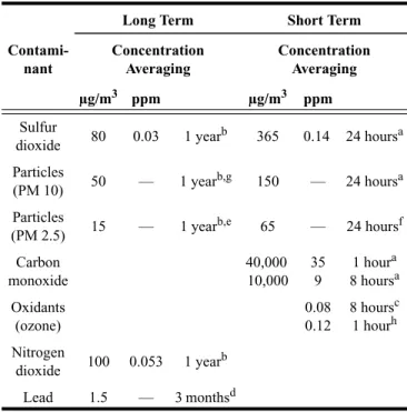
TABLE 4-1 National Primary Ambient Air Quality Standards for Outdoor Air as Set by the U.S. Environmental Protection Agency
Contami-nant
Long Term Short Term
Concentration Averaging Concentration Averaging µg/m3 ppm µg/m3 ppm Sulfur dioxide 80 0.03 1 year b 365 0.14 24 hoursa Particles (PM 10) 50 — 1 year b,g 150 — 24 hoursa Particles (PM 2.5) 15 — 1 year b,e 65 — 24 hoursf Carbon monoxide 40,000 10,000 35 9 1 houra 8 hoursa Oxidants (ozone) 0.08 0.12 8 hoursc 1 hourh Nitrogen dioxide 100 0.053 1 year b Lead 1.5 — 3 monthsd
aNot to be exceeded more than once per year. bAnnual arithmetic mean.
cThe three-year average of the fourth-highest daily maximum eight-hour average ozone concentrations measured at each monitor within an area over each year must not exceed 0.08 ppm.
dThree-month period is a calendar quarter. eThree-year average of the annual arithmetic mean.
fThe three-year average of the 98th percentile of 24-hour concentrations. gThe annual arithmetic mean.
h(1) The standard is attained when the expected number of days per calendar year with maximum hourly average concentrations above 0.12 ppm is ≤1, as determined by Appendix H (40 CFR 50). (2) The one-hour NAAQS will no longer apply to an area one year after the effective date of the designation of that area for the eight-hour ozone NAAQS. The effective designation date for most areas is June 15, 2004 (40 CFR 50.9; see Federal Register of April 30, 2004 [69 FR 23996]).
5.2 Ventilation Air Distribution. Ventilating systems shall be designed in accordance with the following.
5.2.1 Designing for Air Balancing. The ventilation air distribution system shall be provided with means to adjust the system to achieve at least the minimum ventilation airflow as required by Section 6 under any load condition.
5.2.2 Plenum Systems. When the ceiling or floor plenum is used both to recirculate return air and to distribute ventila-tion air to ceiling-mounted or floor-mounted terminal units, the system shall be engineered such that each space is pro-vided with its required minimum ventilation airflow.
Note: Direct connection of ventilation air ducts to
venti-lating terminal units is an alternate method of satisfying the intent of this requirement.
5.2.3 Documentation. The design documents shall
spec-ify minimum requirements for air balance testing or reference applicable national standards for measuring and balancing airflow. The design documentation shall state assumptions that were made in the design with respect to ventilation rates and air distribution.
5.3 Exhaust Duct Location. Exhaust ducts that convey
potentially harmful contaminants shall be negatively pressur-ized relative to spaces through which they pass, so that exhaust air cannot leak into occupied spaces; supply, return, or outdoor air ducts; or plenums.
Exception: Exhaust ducts that are sealed in accordance with
SMACNA Seal Class A.2
5.4 Ventilation System Controls. Mechanical ventilation
systems shall include controls, manual or automatic, that enable the fan system to operate whenever the spaces served are occupied. The system shall be designed to maintain the
minimum outdoor airflow as required by Section 6 under any load condition.
Note: VAV systems with fixed outdoor air damper
posi-tions must comply with this requirement at minimum supply airflow.
5.5 Airstream Surfaces. All airstream surfaces in equip-ment and ducts in the heating, ventilating, and air-condition-ing system shall be designed and constructed in accordance with the following requirements.
5.5.1 Resistance to Mold Growth. Material surfaces
shall be determined to be resistant to mold growth in accor-dance with a standardized test method, such as the “Mold
Growth and Humidity Test” in UL 181,10 ASTM C 1338,11 or
comparable test methods.
Exception: Sheet metal surfaces and metal fasteners.
Note: Even with this resistance, any airstream surface
that is continuously wetted is still subject to microbial growth.
5.5.2 Resistance to Erosion. Airstream surface materials shall be evaluated in accordance with the “Erosion Test” in
UL 18110 and shall not break away, crack, peel, flake off, or
show evidence of delamination or continued erosion under test conditions.
Exception: Sheet metal surfaces and metal fasteners.
5.6 Outdoor Air Intakes. Ventilation system outdoor
intakes shall be designed in accordance with the following.
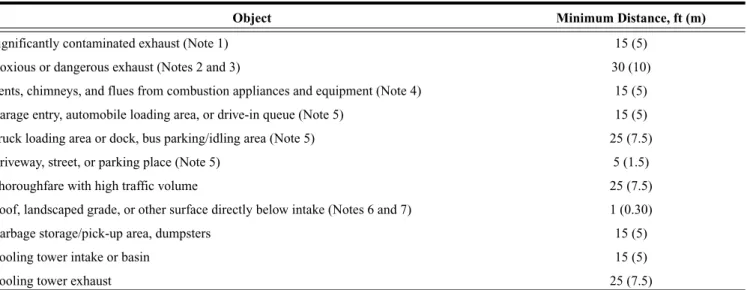
5.6.1 Location. Outdoor air intakes, including doors and windows that are required as part of a natural ventilation sys-tem, shall be located such that the shortest distance from the intake to any specific potential outdoor contaminant source shall be equal to or greater than the separation distance listed in Table 5-1.
TABLE 5-1 Air Intake Minimum Separation Distance
Object Minimum Distance, ft (m)
Significantly contaminated exhaust (Note 1) 15 (5) Noxious or dangerous exhaust (Notes 2 and 3) 30 (10) Vents, chimneys, and flues from combustion appliances and equipment (Note 4) 15 (5) Garage entry, automobile loading area, or drive-in queue (Note 5) 15 (5) Truck loading area or dock, bus parking/idling area (Note 5) 25 (7.5) Driveway, street, or parking place (Note 5) 5 (1.5) Thoroughfare with high traffic volume 25 (7.5) Roof, landscaped grade, or other surface directly below intake (Notes 6 and 7) 1 (0.30) Garbage storage/pick-up area, dumpsters 15 (5)
Cooling tower intake or basin 15 (5)
Cooling tower exhaust 25 (7.5)
Note 1: Significantly contaminated exhaust is exhaust air with significant contaminant concentration, significant sensory-irritation intensity, or offensive odor. Note 2: Laboratory fume hood exhaust air outlets shall be in compliance with NFPA 45-19913 and ANSI/AIHA Z9.5-1992.4
Note 3: Noxious or dangerous exhaust is exhaust air with highly objectionable fumes or gases and/or exhaust air with potentially dangerous particles, bioaerosols, or gases at concen-trations high enough to be considered harmful. Information on separation criteria for industrial environments can be found in the ACGIH Industrial Ventilation Manual 5 and in the ASHRAE Handbook—HVAC Applications.6
Note 4: Shorter separation distances are permitted when determined in accordance with (a) Chapter 7 of ANSI Z223.1/NFPA 54-20027 for fuel gas burning appliances and equipment, (b) Chapter 6 of NFPA 31-20018 for oil burning appliances and equipment, or (c) Chapter 7 of NFPA 211-20039 for other combustion appliances and equipment.
Note 5: Distance measured to closest place that vehicle exhaust is likely to be located.
Note 6: No minimum separation distance applies to surfaces that are sloped more than 45 degrees from horizontal or that are less than 1 in. (3 cm) wide. Note 7: Where snow accumulation is expected, distance listed shall be increased by the expected average snow depth.
Exception: Other minimum separation distances are accept-able if it can be shown that an equivalent or lesser rate of introduction of outdoor air contaminants will be attained.
Note: Appendix F presents an acceptable alternative
method of determining the minimum separation distance.
5.6.2 Rain Entrainment. Outdoor air intakes that are part of the mechanical ventilation system shall be designed to manage rain entrainment in accordance with any one of the following:
a. Limit water penetration through the intake to 0.07 oz/ft2⋅h
(21.5 g/m2⋅h) of inlet area when tested using the rain test
apparatus described in Section 58 of UL 1995.12
b. Select louvers that limit water penetration to a maximum
of 0.01 oz/ft2 (3 g/m2) of louver free area at the maximum
intake velocity. This water penetration rate shall be deter-mined for a minimum 15-minute test duration when sub-jected to a water flow rate of 0.25 gal/min (16 mL/s) as described under the Water Penetration Test in AMCA
500-L-9913 or equivalent. Manage the water that
pene-trates the louver by providing a drainage area and/or moisture removal devices.
c. Select louvers that restrict wind-driven rain penetration to
less than 2.36 oz/ft2⋅h (721 g/m2⋅h) when subjected to a
simulated rainfall of 3 in. (75 mm) per hour and a 29 mph (13 m/s) wind velocity at the design outdoor air intake rate with the air velocity calculated based on the louver face area.
Note: This performance corresponds to Class A (99%
effectiveness) when rated according to AMCA 511-9914
and tested per AMCA 500-L-99.13
d. Use rain hoods sized for no more than 500 fpm (2.5 m/s)
face velocity with a downward-facing intake such that all intake air passes upward through a horizontal plane that intersects the solid surfaces of the hood before entering the system.
e. Manage the water that penetrates the intake opening by
providing a drainage area and/or moisture removal devices.
5.6.3 Rain Intrusion. Air-handling and distribution
equipment mounted outdoors shall be designed to prevent rain intrusion into the airstream when tested at design airflow and with no airflow, using the rain test apparatus described in
Sec-tion 58 of UL 1995.12
5.6.4 Snow Entrainment. Where climate dictates,
out-door air intakes that are part of the mechanical ventilation sys-tem shall be designed to manage melted snow blown or drawn into the system as follows:
a. Suitable access doors to permit cleaning shall be
pro-vided.
b. Outdoor air ductwork or plenums shall pitch to drains
designed in accordance with the requirements of Section 5.11.
5.6.5 Bird Screens. Outdoor air intakes shall include a screening device designed to prevent penetration by a 0.5 in. (13 mm) diameter probe. The screening device material shall be corrosion resistant. The screening device shall be located, or other measures shall be taken, to prevent bird nesting within the outdoor air intake.
Note: Any horizontal surface may be subject to bird
nesting.
5.7 Local Capture of Contaminants. The discharge from
noncombustion equipment that captures the contaminants generated by the equipment shall be ducted directly to the outdoors.
Exception: Equipment specifically designed for discharge
indoors in accordance with the manufacturer’s recom-mendations.
5.8 Combustion Air. Fuel-burning appliances, both
vented and unvented, shall be provided with sufficient air for combustion and adequate removal of combustion products, in accordance with manufacturer instructions. Products of combustion from vented appliances shall be vented directly outdoors.
5.9 Particulate Matter Removal. Particulate matter filters or air cleaners having a minimum efficiency reporting value (MERV) of not less than 6 when rated in accordance with
ANSI/ASHRAE Standard 52.215 shall be provided upstream
of all cooling coils or other devices with wetted surfaces through which air is supplied to an occupiable space.
5.10 Dehumidification Systems. Mechanical
air-condi-tioning systems with dehumidification capability shall be designed to comply with the following.
5.10.1 Relative Humidity. Occupied space relative
humidity shall be limited to 65% or less when system perfor-mance is analyzed with outdoor air at the dehumidification design condition (that is, design dew point and mean coinci-dent dry-bulb temperatures) and with the space interior loads (both sensible and latent) at cooling design values and space solar loads at zero.
Note: System configuration and/or climatic conditions
may adequately limit space relative humidity at these condi-tions without additional humidity-control devices. The speci-fied conditions challenge the system dehumidification performance with high outdoor latent load and low space sensible heat ratio.
Exception: Spaces where process or occupancy
require-ments dictate higher humidity conditions, such as kitch-ens, hot tub rooms that contain heated standing water, refrigerated or frozen storage rooms and ice rinks, and/ or spaces designed and constructed to manage moisture, such as shower rooms, pools, and spas.
5.10.2 Exfiltration. For a building, the design minimum outdoor air intake shall be greater than the design maximum exhaust airflow when the mechanical air-conditioning sys-tems are dehumidifying.
Exception: Where excess exhaust is required by process considerations and approved by the authority having jurisdiction, such as in certain industrial facilities.
Note: Although individual zones within a building may
be neutral or negative with respect to outdoors or to other zones, net positive mechanical intake airflow for the building as a whole reduces infiltration of untreated outdoor air.
5.11 Drain Pans. Drain pans, including their outlets and seals, shall be designed and constructed in accordance with this section.
5.11.1 Drain Pan Slope. Pans intended to collect and
drain liquid water shall be sloped at least 0.125 in. per foot (10 mm per meter) from the horizontal toward the drain outlet or shall be otherwise designed to ensure that water drains freely from the pan whether the fan is on or off.
5.11.2 Drain Outlet. The drain pan outlet shall be located at the lowest point(s) of the drain pan and shall be of sufficient diameter to preclude drain pan overflow under any normally expected operating condition.
5.11.3 Drain Seal. For configurations that result in neg-ative static pressure at the drain pan relneg-ative to the drain out-let (such as a draw-through unit), the drain line shall include a P-trap or other sealing device designed to maintain a seal against ingestion of ambient air while allowing complete drainage of the drain pan under any normally expected oper-ating condition, whether the fan is on or off.
5.11.4 Pan Size. The drain pan shall be located under the water-producing device. Drain pan width shall be sufficient to collect water droplets across the entire width of the water-producing device or assembly. For horizontal airflow config-urations, the drain pan length shall begin at the leading face or edge of the water-producing device or assembly and extend downstream from the leaving face or edge to a dis-tance of either:
a. one half of the installed vertical dimension of the
water-producing device or assembly, or
b. as necessary to limit water droplet carryover beyond the
drain pan to 0.0044 oz per ft2 (1.5 mL per m2) of face
area per hour under peak sensible and peak dew point design conditions, considering both latent load and coil face velocity.
5.12 Finned-Tube Coils and Heat Exchangers
5.12.1 Drain Pans. A drain pan in accordance with Sec-tion 5.11 shall be provided beneath all dehumidifying cooling coil assemblies and all condensate-producing heat exchangers.
5.12.2 Finned-Tube Coil Selection for Cleaning.
Indi-vidual finned-tube coils or multiple finned-tube coils in series without adequate intervening access space(s) of at least 18 in. (457 mm) shall be selected to result in no more than 0.75 in. w.c. (187 Pa) combined pressure drop when dry coil face velocity is 500 fpm (2.54 m/s).
Exception: When clear and complete instructions for access and cleaning of both upstream and downstream coil sur-faces are provided.
5.13 Humidifiers and Water-Spray Systems. Steam and
direct evaporation humidifiers, air washers, and other water-spray systems shall be designed in accordance with this section.
5.13.1 Water Quality. Water shall originate directly from a potable source or from a source with equal or better water quality.
5.13.2 Obstructions. Air cleaners or ductwork obstruc-tions, such as turning vanes, volume dampers, and duct offsets greater than 15 degrees, that are installed downstream of humidifiers or water spray systems shall be located a distance equal to or greater than the absorption distance recommended by the humidifier or water spray system manufacturer.
Exception: Equipment such as eliminators, coils, or evapo-rative media may be located within the absorption dis-tance recommended by the manufacturer, provided a drain pan complying with the requirements of Section 5.11 is used to capture and remove any water that may drop out of the airstream due to impingement on these obstructions.
5.14 Access for Inspection, Cleaning, and Maintenance
5.14.1 Equipment Clearance. Ventilation equipment
shall be installed with sufficient working space for inspection and routine maintenance (e.g., filter replacement and fan belt adjustment and replacement).
5.14.2 Ventilation Equipment Access. Access doors,
panels, or other means shall be provided and sized to allow convenient and unobstructed access sufficient to inspect, maintain, and calibrate all ventilation system components for which routine inspection, maintenance, or calibration is nec-essary. Ventilation system components comprise, for exam-ple, air-handling units, fan-coil units, water-source heat pumps, other terminal units, controllers, and sensors.
5.14.3 Air Distribution System. Access doors, panels, or other means shall be provided in ventilation equipment, duct-work, and plenums, located and sized to allow convenient and unobstructed access for inspection, cleaning, and routine maintenance of the following:
a. Outdoor air intake areaways or plenums
b. Mixed air plenums
c. Upstream surface of each heating, cooling, and
heat-recovery coil or coil assembly having a total of four rows or less
d. Both upstream and downstream surface of each heating,
cooling, and heat-recovery coil having a total of more than four rows and air washers, evaporative coolers, heat wheels, and other heat exchangers
e. Air cleaners
f. Drain pans and drain seals
g. Fans
h. Humidifiers
5.15 Building Envelope and Interior Surfaces. The build-ing envelope and interior surfaces within the buildbuild-ing enve-lope shall be designed in accordance with the following.
5.15.1 Building Envelope. The building envelope, including roofs, walls, fenestration systems, and foundations, shall comply with the following:
1. A weather barrier or other means shall be provided to
prevent liquid water penetration into the envelope.
Exception: When the envelope is engineered to allow
incidental water penetration to occur without result-ing in damage to the envelope construction.
2. An appropriately placed vapor retarder or other means shall
be provided to limit water vapor diffusion to prevent condensation on cold surfaces within the envelope.
Exception: When the envelope is engineered to manage incidental condensation without resulting in dam-age to the envelope construction.
3. Exterior joints, seams, or penetrations in the building
enve-lope that are pathways for air leakage shall be caulked, gasketed, weather-stripped, provided with continuous air barrier, or otherwise sealed to limit infiltration through the envelope to reduce uncontrolled entry of outdoor air mois-ture and pollutants.
Note: Where soils contain high concentrations of radon
or other soil gas contaminants, the local authority having jurisdiction may have additional requirements, such as depressurization.
5.15.2 Condensation on Interior Surfaces. Pipes, ducts, and other surfaces within the building whose surface temper-atures are expected to fall below the surrounding dew-point temperature shall be insulated. The insulation system thermal resistance and material characteristics shall be sufficient to prevent condensation from forming on the exposed surface and within the insulating material.
Exceptions:
a. Where condensate will wet only surfaces that can be
managed to prevent or control mold growth.
b. Where local practice has demonstrated that
conden-sation does not result in mold growth.
5.16 Buildings with Attached Parking Garages. In order
to limit the entry of vehicular exhaust into occupiable spaces, buildings with attached parking garages shall:
1. maintain the garage pressure at or below the pressure of the
adjacent occupiable spaces, or
2. use a vestibule to provide an airlock between the garage and
the adjacent occupiable spaces, or
3. otherwise be designed to minimize migration of air from
the attached parking garage into the adjacent occupiable spaces of the building.
5.17 Air Classification and Recirculation. Air shall be
classified, and its recirculation shall be limited in accordance with the following sections.
5.17.1 Classification. Air (return, transfer, or exhaust air) leaving each space or location shall be designated at an expected air-quality classification not less than that shown in Tables 5-2 or 6-1 or as approved by the authority having
jurisdiction. The classification for air from spaces or loca-tions that are not listed in Tables 5-2 or 6-1 shall be the same as the classification for air from the listed space type that is most similar in terms of occupant activities and building construction.
Exception: Classification of air from smoking spaces is not addressed. (Spaces that are expected to include smoking do not have a classification listed in Table 6-1.)
Note: Classifications in Tables 5-2 and 6-1 are based on
relative contaminant concentration using the following subjective criteria:
• Class 1: Air with low contaminant concentration, low
sensory-irritation intensity, and inoffensive odor.
• Class 2: Air with moderate contaminant concentration,
mild sensory-irritation intensity, or mildly offensive odors. Class 2 air also includes air that is not necessar-ily harmful or objectionable but that is inappropriate for transfer or recirculation to spaces used for different purposes.
• Class 3: Air with significant contaminant concentration,
significant sensory-irritation intensity, or offensive odor.
• Class 4: Air with highly objectionable fumes or gases or
with potentially dangerous particles, bioaerosols, or gases, at concentrations high enough to be considered harmful.
5.17.2 Re-designation
5.17.2.1 Air Cleaning. If air leaving a space or location passes through an air-cleaning system, the cleaned air may be reclassified to a cleaner classification, using the subjective criteria noted above, with the approval of the authority having jurisdiction.
5.17.2.2 Energy Recovery. Class 2 air may be re-desig-nated as Class 1 air in the process of recovering energy when it is diluted with outdoor air such that no more than 10% of the resulting airstream is Class 2 air. Class 3 air may be re-desig-nated as Class 1 air in the process of recovering energy when it is diluted with outdoor air such that no more than 5% of the resulting airstream is Class 3 air.
5.17.2.3 Transfer. A mixture of air that has been trans-ferred through or returned from more than one classification of space must be re-designated with the classification appro-priate for the part of the mixture that has the highest
contam-inant concentration. For example, air returned from both a
Class 1 and a Class 2 space served by a common system must be designated as Class 2 air.
TABLE 5-2 Airstreams
Description Air Class
Diazo printing equipment discharge 4 Commercial kitchen grease hoods 4 Commercial kitchen hoods other than grease 3 Laboratory hoods 4 Residential kitchen vented hoods 3
5.17.3 Recirculation Limitations. When the Ventilation Rate Procedure of Section 6 is used to determine ventilation air-flow values, recirculation of air shall be limited in accordance with the requirements of this section.
5.17.3.1 Class 1 Air. Class 1 air may be recirculated or transferred to any space.
5.17.3.2 Class 2 Air. Class 2 air may be recirculated within the space of origin. Class 2 air may be transferred or recirculated to other Class 2 or Class 3 spaces utilized for the same or similar purpose or task and involving the same or sim-ilar pollutant sources. Class 2 air may be recirculated or trans-ferred to Class 4 spaces. Class 2 air shall not be recirculated or transferred to Class 1 spaces.
Note: Spaces that are normally Class 1 may be identified
as “Spaces ancillary to Class 2 spaces” and as such classified as Class 2 spaces as permitted in Table 6-1.
5.17.3.3 Class 3 Air. Class 3 air may be recirculated within the space of origin. Class 3 air shall not be recirculated or transferred to any other space.
5.17.3.4 Class 4 Air. Class 4 air shall not be recirculated or transferred to any space nor recirculated within the space of origin.
5.17.4 Documentation. Design documentation shall indi-cate the justification for classification of air from any location not listed in Tables 5-2 or 6-1.
5.18 Requirements for Buildings Containing ETS Areas
and ETS-Free Areas. The requirements of this section must be met when a building contains both ETS areas and ETS-free areas. Such buildings shall be constructed and operated in accordance with Sections 5.18.1 through 5.18.8. This section does not purport to achieve acceptable indoor air quality in ETS areas.
5.18.1 Classification. All spaces shall be classified as either ETS-free areas or ETS areas.
5.18.2 Pressurization. ETS-free areas shall be at a posi-tive pressure with respect to any adjacent or connected ETS areas.
Note: Examples of methods for demonstrating relative
pressure include engineering analysis, pressure differential measurement, and airflow measurement.
Exceptions:
a. Dwelling units, including hotel and motel
gues-trooms, and adjacent properties under different own-ership with separation walls that are structurally independent and that contain no openings. This exception shall apply only when:
1. the separation walls are constructed as smoke barriers in accordance with the requirements of applicable standards;
2. the separation walls include an air barrier consist-ing of a continuous membrane or surface treatment in the separation wall that has documented resis-tance to air leakage; continuity of the barrier shall be maintained at openings for pipes, ducts, and other conduits and at points where the barrier meets the outside walls and other barriers; and
3. interior corridors common to ETS and ETS-free areas are mechanically supplied with outdoor air at
the rate of 0.1 cfm/ft2 (0.5 L/s⋅m2).
b. Adjacent spaces otherwise required to be held at
neg-ative pressure and posted with signs due to the pres-ence of hazardous or flammable materials or vapors.
5.18.3 Separation. Solid walls, floors, ceilings, and doors equipped with automatic closing mechanisms shall separate ETS areas from ETS-free areas.
Exception: Openings without doors are permitted in the
separation where engineered systems are designed to provide airflow from ETS-free areas into ETS areas, notwithstanding eddies that may occur in the immediate vicinity of the boundary between the ETS and ETS-free areas and reverse flow that may occur due to short-term conditions such as wind gusts.
Note: Examples of methods for demonstrating air motion
are engineering analysis and the use of a directional airflow indicator at representative locations in the opening, such as on 1 ft (0.3 m) centers or at locations required for duct traverses in standard testing and balancing procedures, such as those
described in ASHRAE Standard 111.21
5.18.4 Transfer Air. When air is transferred from ETS-free areas to ETS areas, the transfer airflow rate shall be main-tained regardless of whether operable doors or windows between ETS-free and ETS areas are opened or closed. Acceptable means of doing so include fixed openings in doors, walls, or floors, transfer grilles, transfer ducts, or unducted air plenums with air pressure differentials in com-pliance with Section 5.18.2.
5.18.5 Recirculation. Air-handling and natural ventila-tion systems shall not recirculate or transfer air from an ETS area to an ETS-free area.
5.18.6 Exhaust Systems. Exhaust or relief air from an
ETS area shall be discharged such that none of the air is recir-culated back into any ETS-free area.
5.18.7 Signage. A sign shall be posted outside each
entrance to each ETS area. The sign shall state, as a minimum, “This Area May Contain Environmental Tobacco Smoke” in letters at least 1 in. (25 mm) high or otherwise in compliance with accessibility guidelines.
Note: Based on the definition of ETS area, such a sign
may be posted outside a larger ETS area that includes the area where smoking is permitted.
Exception: Instead of the specified sign, equivalent notifica-tion means acceptable to the authority having jurisdic-tion may be used.
5.18.8 Reclassification. An area that was previously an ETS area, but now meets the requirements of an ETS-free area, may be classified as such after intentional or allowed smoke exposure has stopped and odor and irritation from residual ETS contaminants are not apparent.
6. PROCEDURES
This section is not required for natural ventilation systems; natural ventilation systems shall be designed in accordance with Section 5.1.
6.1 General. Either the Ventilation Rate Procedure or the IAQ Procedure shall be used to design each ventilation system in a building, subject to the following considerations and restrictions.
6.1.1 Ventilation Rate Procedure. This is a prescriptive procedure in which outdoor air intake rates are determined based on space type/application, occupancy level, and floor area.
Note: The Ventilation Rate Procedure minimum rates are
based on contaminant sources and source strengths that are typical for the listed space types.
6.1.2 IAQ Procedure. This is a design procedure in
which outdoor air intake rates and other system design param-eters are based on an analysis of contaminant sources, con-taminant concentration targets, and perceived acceptability targets. The IAQ Procedure allows credit to be taken for con-trols that remove contaminants (for example, air-cleaning devices) or for other design techniques (for example, selec-tion of materials with lower source strengths) that can be reli-ably demonstrated to result in indoor contaminant concentrations equal to or lower than those achieved using the Ventilation Rate Procedure. The IAQ Procedure may also be used where the design is intended to attain specific target con-taminant concentrations or levels of acceptability of perceived indoor air quality.
6.2 Ventilation Rate Procedure. The design outdoor air
intake flow (Vot) for a ventilation system shall be determined in accordance with Sections 6.2.1 through 6.2.9.
Note: Additional explanation of terms used below is
contained in Appendix A, along with a ventilation system schematic (Figure A.1).
6.2.1 Outdoor Air Treatment. If outdoor air is judged to be unacceptable in accordance with Section 4.1, each ventila-tion system that provides outdoor air through a supply fan shall comply with the following sections.
Exception: Systems supplying air for enclosed parking
garages, warehouses, storage rooms, janitor’s closets, trash rooms, recycling areas, shipping/receiving/distri-bution areas.
Note: Occupied spaces ventilated with outdoor air that is
judged to be unacceptable are subject to reduced air quality when outdoor air is not cleaned prior to introduction to the occupied spaces.
6.2.1.1 Particulate Matter. When the building is
located in an area where the national standard for PM101 is
exceeded, particle filters or air-cleaning devices shall be pro-vided to clean the air at any location prior to its introduction to occupied spaces. Particulate matter filters or air cleaners shall have a Minimum Efficiency Reporting Value (MERV) of 6 or higher when rated in accordance with ANSI/ASHRAE
Standard 52.2.15
6.2.1.2 Ozone. Air-cleaning devices for ozone shall be provided when the second-highest daily maximum one-hour
average concentration exceeds 0.160 ppm (313 μg/m3). The
ozone concentration for design purposes shall be determined
in accordance with Appendix H to subchapter C, 40 CFR 50,1
or equivalent.
Note: Monitored values for historical one-hour average
ozone concentrations are available for United States locations at the AIRData Web site, located under www.epa.gov.
Such air-cleaning devices shall have a minimum volumet-ric ozone removal efficiency of 40% when installed, operated, and maintained in accordance with manufacturer recommen-dations and shall be approved by the authority having juris-diction. Such devices shall be operated whenever outdoor
ozone levels are expected to exceed 0.160 ppm (313 μg/m3).
Note: For United States locations, the one-hour average
ozone concentration is expected to exceed the 0.160 ppm
(313μg/m3) limit when the Air Quality Index forecast
exceeds 151 (category red, purple, or maroon). This forecast is available in local media or at the AIRNow Web site, located under www.epa.gov.
Exceptions:Air cleaning for ozone is not required when:
a. The minimum system design outdoor air intake flow
results in 1.5 ach or less.
b. Controls are provided that sense outdoor ozone level
and reduce intake airflow to result in 1.5 ach or less while complying with the outdoor airflow require-ments of Section 6.
c. Outdoor air is brought into the building and heated
by direct-fired, makeup air units.
6.2.1.3 Other Outdoor Contaminants. When the
building is located in an area where the national standard for one or more contaminants not specifically addressed in Sec-tion 6.2.1 is exceeded, any design assumpSec-tions and/or calcu-lations related to the impact on indoor air quality shall be included in the design documents.
6.2.2 Zone Calculations. Zone parameters shall be deter-mined in accordance with Sections 6.2.2.1 through 6.2.2.3.
Note: In some cases it is acceptable to determine these
parameters for only selected zones as outlined in Appendix A.
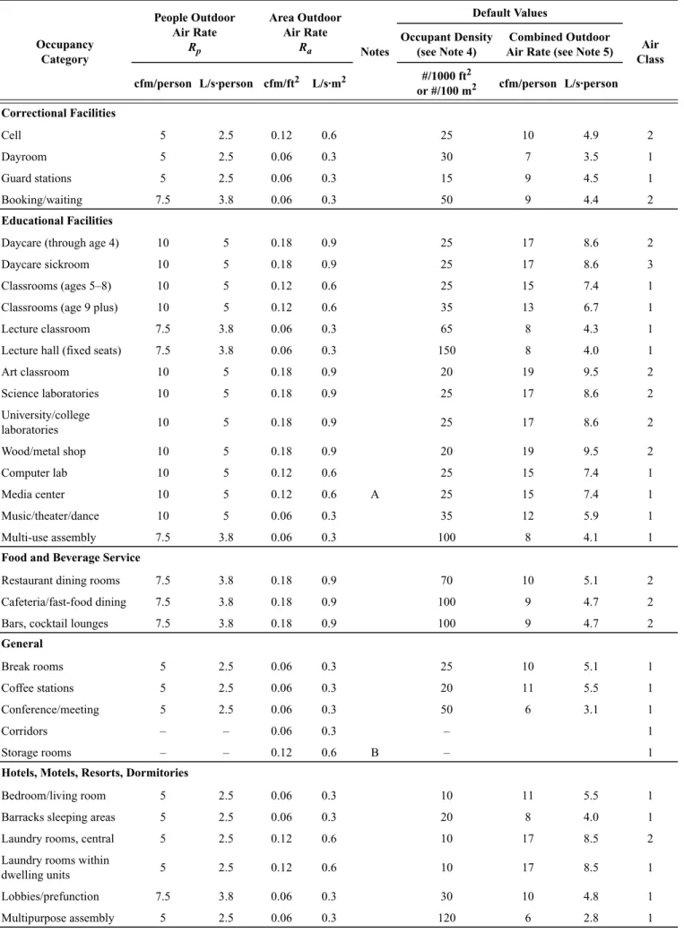
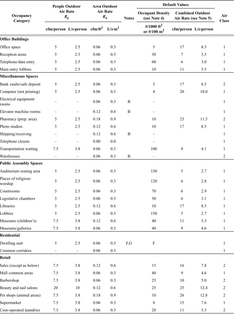
6.2.2.1 Breathing Zone Outdoor Airflow. The design
outdoor airflow required in the breathing zone of the occupi-able space or spaces in a zone, i.e., the breathing zone outdoor airflow (Vbz), shall be determined in accordance with
Equa-tion 6-1.
Vbz = Rp · Pz + Ra · Az (6-1)
where
Az = zone floor area: the net occupiable floor area of the zone m2 (ft2)
Pz = zone population: the largest number of people expected to occupy the zone during typical usage. If the number of people expected to occupy the zone
fluctuates, Pz may be estimated based on averaging
Note: If Pz cannot be accurately predicted during design, it shall be an estimated value based on the zone floor area and the default occupant density listed in Table 6-1.
Rp = outdoor airflow rate required per person as
determined from Table 6-1
Note: These values are based on adapted occupants.
Ra = outdoor airflow rate required per unit area as
determined from Table 6-1
Note: Equation 6-1 is the means of accounting for
people-related sources and area-related sources for determin-ing the outdoor air required at the breathdetermin-ing zone. The use of Equation 6-1 in the context of this standard does not necessar-ily imply that simple addition of sources can be applied to any other aspect of indoor air quality.
6.2.2.2 Zone Air Distribution Effectiveness. The zone air distribution effectiveness (Ez) shall be determined using Table 6-2.
6.2.2.3 Zone Outdoor Airflow. The design zone
out-door airflow (Voz), i.e., the outdoor airflow that must be pro-vided to the zone by the supply air distribution system, shall be determined in accordance with Equation 6-2.
Voz = Vbz/Ez (6-2)
6.2.3 Single-Zone Systems. When one air handler
sup-plies a mixture of outdoor air and recirculated air to only one
zone, the outdoor air intake flow (Vot) shall be determined in
accordance with Equation 6-3.
Vot = Voz (6-3)
6.2.4 100% Outdoor Air Systems. When one air handler
supplies only outdoor air to one or more zones, the outdoor air intake flow (Vot) shall be determined in accordance with Equation 6-4.
Vot = Σall zonesVoz (6-4)
6.2.5 Multiple-Zone Recirculating Systems. When one
air handler supplies a mixture of outdoor air and recirculated return air to more than one zone, the outdoor air intake flow
(Vot) shall be determined in accordance with Sections 6.2.5.1
through 6.2.5.4.
6.2.5.1 Primary Outdoor Air Fraction. When
Table 6-3 is used to determine system ventilation efficiency, the zone primary outdoor air fraction (Zp) shall be deter-mined in accordance with Equation 6-5.
Zp = Voz/Vpz (6-5)
where Vpz is the zone primary airflow, i.e., the primary airflow
to the zone from the air handler including outdoor air and recirculated return air.
Note: For VAV systems, Vpz is the minimum expected
primary airflow for design purposes.
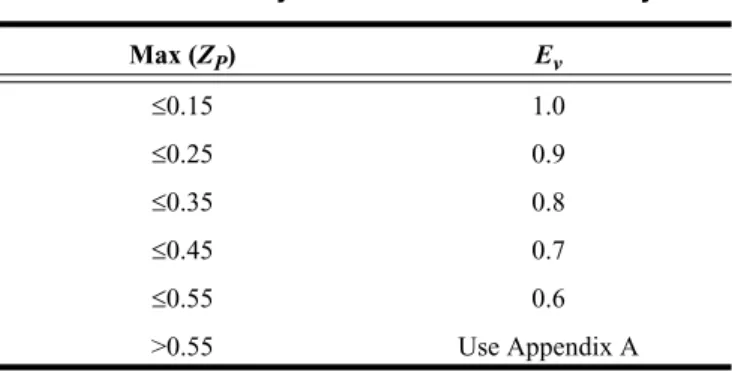
6.2.5.2 System Ventilation Efficiency. The system ven-tilation efficiency (Ev) shall be determined using Table 6-3 or Appendix A.
6.2.5.3 Uncorrected Outdoor Air Intake. The design
uncorrected outdoor air intake (Vou) shall be determined in accordance with Equation 6-6.
Vou = DΣall zones(Rp · Pz) + Σall zones(Ra · Az) (6-6)
The occupant diversity, D, may be used to account for
variations in occupancy within the zones served by the system. The occupancy diversity is defined as
D = Ps/Σall zones Pz , (6-7)
where the system population (Ps) is the total population in the
area served by the system. Alternative methods may be used
to account for population diversity when calculating Vou,
provided that the resulting value is no less than that deter-mined by Equation 6-6.
Note: The uncorrected outdoor air intake (Vou) is
adjusted for diversity but uncorrected for ventilation effi-ciency.
6.2.5.4 Outdoor Air Intake. The design outdoor air
intake flow (Vot) shall be determined in accordance with Equation 6-8.
Vot = Vou/Ev (6-8)
6.2.6 Design for Varying Operating Conditions
6.2.6.1 Variable Load Conditions. Ventilation systems shall be designed to be capable of providing the required ven-tilation rates in the breathing zone whenever the zones served by the system are occupied, including all full- and part-load conditions.
6.2.6.2 Short-Term Conditions. If it is known that
peak occupancy will be of short duration and/or ventilation will be varied or interrupted for a short period of time, the design may be based on the average conditions over a time period T determined by Equation 6-9.
T = 3v/Vbz (6-9a)
T = 50v/Vbz (6-9b)
where
T = averaging time period, min
v = the volume of the zone for which averaging is being
applied, ft3 (m3)
Vbz = the breathing zone outdoor airflow calculated using
Equation 6-1 and the design value of the zone
population Pz, cfm (L/s)
Acceptable design adjustments based on this optional provision include the following:
1. Zones with fluctuating occupancy: the zone population (Pz)
may be averaged over time T.
2. Zones with intermittent interruption of supply air: the
aver-age outdoor airflow supplied to the breathing zone over time T shall be no less than the breathing zone outdoor airflow (Vbz) calculated using Equation 6-1.
3. Systems with intermittent closure of the outdoor air intake:
the average outdoor air intake over time T shall be no less
than the minimum outdoor air intake (Vot) calculated using