CHAPTER 4
GAS PIPING INSTALLATIONS
SECTION 401 (IFGC)GENERAL
401.1 Scope.This chapter shall govern the design, installation, modification and maintenance of piping systems. The applica-bility of this code to piping systems extends from the point of delivery to the connections with the equipment and includes the design, materials, components, fabrication, assembly, installa-tion, testing, inspecinstalla-tion, operation and maintenance of such piping systems.
401.1.1 Utility piping systems located within buildings. Utility service piping located within buildings shall be in-stalled in accordance with the structural safety and fire pro-tection provisions of theInternational Building Code. 401.2 Liquefied petroleum gas storage.The storage system for liquefied petroleum gas shall be designed and installed in accordance with theInternational Fire Codeand NFPA 58. 401.3 Modifications to existing systems.In modifying or add-ing to existadd-ing pipadd-ing systems, sizes shall be maintained in ac-cordance with this chapter.
401.4 Additional appliances.Where an additional appliance is to be served, the existing piping shall be checked to deter-mine if it has adequate capacity for all appliances served. If in-adequate, the existing system shall be enlarged as required or separate piping of adequate capacity shall be provided. 401.5 Identification.For other than black steel pipe, exposed piping shall be identified by a yellow label marked “Gas” in black letters. The marking shall be spaced at intervals not ex-ceeding 5 feet (1524 mm). The marking shall not be required on pipe located in the same room as the equipment served. 401.6 Interconnections. Where two or more meters are in-stalled on the same premises but supply separate consumers, the piping systems shall not be interconnected on the outlet side of the meters.
401.7 Piping meter identification.Piping from multiple me-ter installations shall be marked with an approved permanent identification by the installer so that the piping system supplied by each meter is readily identifiable.
401.8 Minimum sizes.All pipe utilized for the installation, ex-tension and alteration of any piping system shall be sized to supply the full number of outlets for the intended purpose and shall be sized in accordance with Section 402.
SECTION 402 (IFGS) PIPE SIZING
402.1 General considerations.Piping systems shall be of such size and so installed as to provide a supply of gas sufficient to meet the maximum demand without undue loss of pressure be-tween the point of delivery and the gas utilization equipment.
402.2 Maximum gas demand.The volume of gas to be pro-vided, in cubic feet per hour, shall be determined directly from the manufacturer’s input ratings of the gas utilization equip-ment served. Where an input rating is not indicated, the gas supplier, equipment manufacturer or a qualified agency shall be contacted, or the rating from Table 402.2 shall be used for estimating the volume of gas to be supplied.
The total connected hourly load shall be used as the basis for pipe sizing, assuming that all equipment could be operating at full capacity simultaneously. Where a diversity of load can be estab-lished, pipe sizing shall be permitted to be based on such loads.
TABLE 402.2
APPROXIMATE GAS INPUT FOR TYPICAL APPLIANCES APPLIANCE
INPUT BTU/H (Approx.)
Space Heating Units Hydronic boiler
Single family 100,000
Multifamily, per unit 60,000
Warm-air furnace
Single family 100,000
Multifamily, per unit 60,000
Space and Water Heating Units Hydronic boiler
Single family 120,000
Multifamily, per unit 75,000
Water Heating Appliances
Water heater, automatic instantaneous 35,000
Capacity at 2 gal./minute 50,000
Capacity at 4 gal./minute
Capacity at 6 gal./minute 142,800
Water heater, automatic storage, 30- to 40-gal. tank 285,000 Water heater, automatic storage, 50-gal. tank 428,400 Water heater, domestic, circulating or side-arm 35,000 Cooking Appliances
Built-in oven or broiler unit, domestic 65,000
Built-in top unit, domestic 25,000
Range, free-standing, domestic 40,000
Other Appliances
Barbecue 3,000
Clothes dryer, Type 1 (domestic) 35,000
Gas fireplace, direct vent 40,000
Gas light 80,000
Gas log 40,000
Refrigerator 2,500
For SI: 1 British thermal unit per hour = 0.293 W, 1 gallon = 3.785 L, 1 gallon per minute = 3.785 L/m.
GAS PIPING INSTALLATIONS
402.3 Sizing. Gas piping shall be sized in accordance with one of
the following:
1. Pipe sizing tables or sizing equations in accordance with Section 402.4.
2. The sizing tables included in a listed piping system’s manufacturer’s installation instructions.
3. Other approved engineering methods.
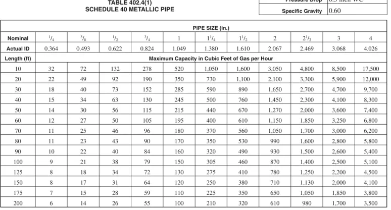
402.4 Sizing tables and equations. Where Tables 402.4(1)
through 402.4(33) are used to size piping or tubing, the pipe length shall be determined in accordance with Section 402.4.1, 402.4.2 or 402.4.3.
Where Equations 4-1 and 4-2 are used to size piping or tubing, the pipe or tubing shall have smooth inside walls and the pipe length shall be determined in accordance with Section 402.4.1, 402.4.2 or 402.4.3. Before Equations 4-1 or 4-2 are permitted to be used, plans stamped by a mechanical engineer licensed in the State of Washington shall be submitted and approved by the code official.
1. Low-pressure gas equation [Less than 1.5 pounds per square inch (psi) (10.3 kPa)]:
206 . 0 381 . 0
17
.
19
⎟⎟
⎠
⎞
⎜⎜
⎝
⎛
×
Δ
=
L
C
H
Q
D
r (Equation 4-1)2. High-pressure gas equation [1.5 psi (10.3 kPa) and above]:
(
2)
0.206 2 2 1 381 . 093
.
18
⎥
⎥
⎦
⎤
⎢
⎢
⎣
⎡
×
×
−
=
L
C
Y
P
P
Q
D
r (Equation 4-2) where:D = Inside diameter of pipe, inches (mm).
Q = Input rate appliance(s), cubic feet per hour at 60°F (16°C) and 30-inch mercury column
P1 = Upstream pressure, psia (P1 + 14.7) P2 = Downstream pressure, psia (P2 + 14.7) L = Equivalent length of pipe, feet
∆H = Pressure drop, inch water column (27.7 inch water column = 1 psi)
TABLE 402.4
Cr AND Y VALUES FOR NATURAL GAS AND UNDILUTED PROPANE AT STANDARD CONDITIONS
EQUATION FACTORS GAS
Cr Y
Natural gas 0.6094 0.9992 Undiluted propane 1.2462 0.9910 For SI: 1 cubic foot = 0.028 m3, 1 foot = 305 mm, 1-inch water
column = 0.249 kPa, 1 pound per square inch = 6.895 kPa, 1 British thermal unit per hour = 0.293 W.
402.4.1 Longest length method. The pipe size of each section
of gas piping shall be determined using the longest length of
piping from the point of delivery to the most remote outlet and the load of the section.
402.4.2 Branch length method. Pipe shall be sized as follows:
1. Pipe size of each section of the longest pipe run from the point of delivery to the most remote outlet shall be determined using the longest run of piping and the load of the section.
2. The pipe size of each section of branch piping not previously sized shall be determined using the length of piping from the point of delivery to the most remote outlet in each branch and the load of the section.
402.4.3 Hybrid pressure. The pipe size for each section of
higher pressure gas piping shall be determined using the longest length of piping from the point of delivery to the most remote line pressure regulator. The pipe size from the line pressure regulator to each outlet shall be determined using the length of piping from the regulator to the most remote outlet served by the regulator.
402.5 Allowable pressure drop. The design pressure loss in any
piping system under maximum probable flow conditions, from the point of delivery to the inlet connection of the equipment, shall be such that the supply pressure at the equipment is greater than the minimum pressure required for proper equipment operation.
402.6 Maximum design operating pressure. The maximum
design operating pressure for piping systems located inside buildings shall not exceed 5 pounds per square inch gauge (psig) (34 kPa gauge) except where one or more of the following conditions are met:
1. The piping system is welded.
2. The piping is located in a ventilated chase or otherwise enclosed for protection against accidental gas accumulation. 3. The piping is located inside buildings or separate areas of
buildings used exclusively for: 3.1. Industrial processing or heating; 3.2. Research;
3.3. Warehousing; or
3.4. Boiler or mechanical equipment rooms.
4. The piping is a temporary installation for buildings under construction.
Plans for piping systems over 5 psig shall be stamped by an engineer licensed to practice in the State of Washington, and shall not be installed until approved by the code official.
402.6.1 Liquefied petroleum gas systems. The operating
pressure for undiluted LP-gas systems shall not exceed 20 psig (140 kPa gauge). Buildings having systems designed to operate below -5°F (-21°C) or with butane or a propane-butane mix shall be designed to either accommodate liquid LP-gas or prevent LP-gas vapor from condensing into a liquid.
Exception: Buildings or separate areas of buildings
constructed in accordance with Chapter 7 of NFPA 58, and used exclusively to house industrial processes, research and experimental laboratories, or equipment or processing having similar hazards.
GAS PIPING INSTALLATIONS
TABLE 402.4(1) SCHEDULE 40 METALLIC PIPE
Gas Natural Inlet Pressure 0.50 psi or less Pressure Drop 0.3 inch WC Specific Gravity 0.60 PIPE SIZE (in.)
Nominal 1/
4 3/8 1/2 3/4 1 11/4 11/2 2 21/2 3 4
Actual ID 0.364 0.493 0.622 0.824 1.049 1.380 1.610 2.067 2.469 3.068 4.026 Length (ft) Maximum Capacity in Cubic Feet of Gas per Hour
10 32 72 132 278 520 1,050 1,600 3,050 4,800 8,500 17,500 20 22 49 92 190 350 730 1,100 2,100 3,300 5,900 12,000 30 18 40 73 152 285 590 890 1,650 2,700 4,700 9,700 40 15 34 63 130 245 500 760 1,450 2,300 4,100 8,300 50 14 30 56 115 215 440 670 1,270 2,000 3,600 7,400 60 12 27 50 105 195 400 610 1,150 1,850 3,250 6,800 70 11 25 46 96 180 370 560 1,050 1,700 3,000 6,200 80 11 23 43 90 170 350 530 990 1,600 2,800 5,800 90 10 22 40 84 160 320 490 930 1,500 2,600 5,400 100 9 21 38 79 150 305 460 870 1,400 2,500 5,100 125 8 18 34 72 130 275 410 780 1,250 2,200 4,500 150 8 17 31 64 120 250 380 710 1,130 2,000 4,100 175 7 15 28 59 110 225 350 650 1,050 1,850 3,800 200 6 14 26 55 100 210 320 610 980 1,700 3,500
For SI: 1 inch = 25.4 mm, 1 foot = 304.8 mm, 1 cubic foot per hour = 0.0283 m3/h, 1 pound per square inch = 6.895 kPa, 1-inch water column = 0.2488 kPa.
TABLE 402.4(2) SCHEDULE 40 METALLIC PIPE
Gas Natural Inlet Pressure 0.50 psi or less Pressure Drop 0.5 inch WC Specific Gravity 0.60 PIPE SIZE (in.)
Nominal 1/
4 3/8 1/2 3/4 1 11/4 11/2 2 21/2 3 4
Actual ID 0.364 0.493 0.622 0.824 1.049 1.380 1.610 2.067 2.469 3.068 4.026 Length (ft) Maximum Capacity in Cubic Feet of Gas per Hour
10 43 95 175 360 680 1,400 2,100 3,950 6,300 11,000 23,000 20 29 65 120 250 465 950 1,460 2,750 4,350 7,700 15,800 30 24 52 97 200 375 770 1,180 2,200 3,520 6,250 12,800 40 20 45 82 170 320 660 990 1,900 3,000 5,300 10,900 50 18 40 73 151 285 580 900 1,680 2,650 4,750 9,700 60 16 36 66 138 260 530 810 1,520 2,400 4,300 8,800 70 15 33 61 125 240 490 750 1,400 2,250 3,900 8,100 80 14 31 57 118 220 460 690 1,300 2,050 3,700 7,500 90 13 29 53 110 205 430 650 1,220 1,950 3,450 7,200 100 12 27 50 103 195 400 620 1,150 1,850 3,250 6,700 125 11 24 44 93 175 360 550 1,020 1,650 2,950 6,000 150 10 22 40 84 160 325 500 950 1,500 2,650 5,500 175 9 20 37 77 145 300 460 850 1,370 2,450 5,000 200 8 19 35 72 135 280 430 800 1,280 2,280 4,600
GAS PIPING INSTALLATIONS
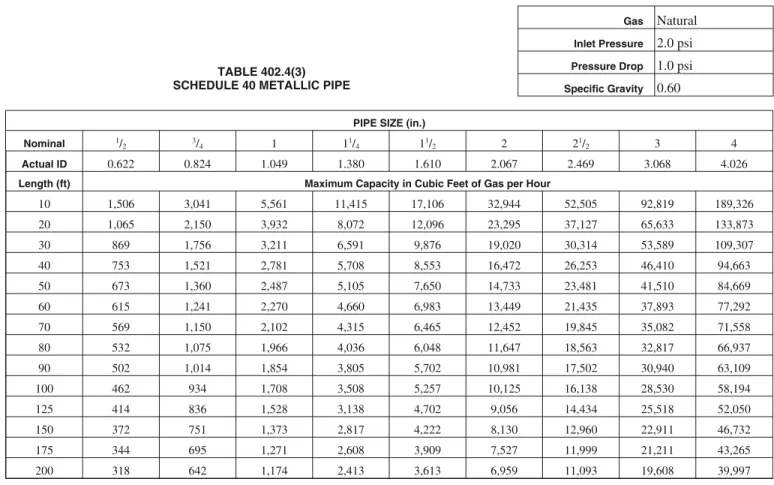
TABLE 402.4(3) SCHEDULE 40 METALLIC PIPE
Gas Natural Inlet Pressure 2.0 psi Pressure Drop 1.0 psi Specific Gravity 0.60 PIPE SIZE (in.)
Nominal 1/
2 3/4 1 11/4 11/2 2 21/2 3 4
Actual ID 0.622 0.824 1.049 1.380 1.610 2.067 2.469 3.068 4.026
Length (ft) Maximum Capacity in Cubic Feet of Gas per Hour
10 1,506 3,041 5,561 11,415 17,106 32,944 52,505 92,819 189,326 20 1,065 2,150 3,932 8,072 12,096 23,295 37,127 65,633 133,873 30 869 1,756 3,211 6,591 9,876 19,020 30,314 53,589 109,307 40 753 1,521 2,781 5,708 8,553 16,472 26,253 46,410 94,663 50 673 1,360 2,487 5,105 7,650 14,733 23,481 41,510 84,669 60 615 1,241 2,270 4,660 6,983 13,449 21,435 37,893 77,292 70 569 1,150 2,102 4,315 6,465 12,452 19,845 35,082 71,558 80 532 1,075 1,966 4,036 6,048 11,647 18,563 32,817 66,937 90 502 1,014 1,854 3,805 5,702 10,981 17,502 30,940 63,109 100 462 934 1,708 3,508 5,257 10,125 16,138 28,530 58,194 125 414 836 1,528 3,138 4,702 9,056 14,434 25,518 52,050 150 372 751 1,373 2,817 4,222 8,130 12,960 22,911 46,732 175 344 695 1,271 2,608 3,909 7,527 11,999 21,211 43,265 200 318 642 1,174 2,413 3,613 6,959 11,093 19,608 39,997
For SI: 1 inch = 25.4 mm, 1 foot = 304.8 mm, 1 cubic foot per hour = 0.0283 m3/h, 1 pound per square inch = 6.895 kPa.
TABLE 402.4(4) SCHEDULE 40 METALLIC PIPE
Gas Natural Inlet Pressure 5.0 psi Pressure Drop 3.5 psi Specific Gravity 0.60 PIPE SIZE (in.)
Nominal 1/
2 3/4 1 11/4 11/2 2 21/2 3 4
Actual ID 0.622 0.824 1.049 1.380 1.610 2.067 2.469 3.068 4.026
Length (ft) Maximum Capacity in Cubic Feet of Gas per Hour
10 3,185 6,434 11,766 24,161 36,206 69,727 111,133 196,468 400,732 20 2,252 4,550 8,320 17,084 25,602 49,305 78,583 138,924 283,361 30 1,839 3,715 6,793 13,949 20,904 40,257 64,162 113,431 231,363 40 1,593 3,217 5,883 12,080 18,103 34,864 55,566 98,234 200,366 50 1,425 2,878 5,262 10,805 16,192 31,183 49,700 87,863 179,213 60 1,301 2,627 4,804 9,864 14,781 28,466 45,370 80,208 163,598 70 1,204 2,432 4,447 9,132 13,685 26,354 42,004 74,258 151,463 80 1,153 2,330 4,260 8,542 12,801 24,652 39,291 69,462 141,680 90 1,062 2,145 3,922 8,054 12,069 23,242 37,044 65,489 133,577 100 979 1,978 3,617 7,427 11,128 21,433 34,159 60,387 123,173 125 876 1,769 3,235 6,643 9,953 19,170 30,553 54,012 110,169 150 786 1,589 2,905 5,964 8,937 17,211 27,431 48,494 98,911 175 728 1,471 2,690 5,522 8,274 15,934 25,396 44,897 91,574 200 673 1,360 2,487 5,104 7,649 14,729 23,478 41,504 84,656
GAS PIPING INSTALLATIONS
TABLE 402.4(6) SCHEDULE 40 METALLIC PIPE
Gas Natural Inlet Pressure 1.0 psi or less Pressure Drop 0.5 inch WC Specific Gravity 0.60
PIPE SIZE (in.)
Nominal 1 11/
4 11/2 2 21/2 3 31/2 4 5 6 8 10 12
Actual ID 1.049 1.380 1.610 2.067 2.469 3.068 3.548 4.026 5.047 6.065 7.981 10.020 11.938 Length (ft) Maximum Capacity in Cubic Feet of Gas per Hour
50 284 583 873 1,681 2,680 4,738 6,937 9,663 17,482 28,308 58,161 105,636 167,236 100 195 400 600 1,156 1,842 3,256 4,767 6,641 12,015 19,456 39,974 72,603 114,940 150 157 322 482 928 1,479 2,615 3,828 5,333 9,649 15,624 32,100 58,303 92,301 200 134 275 412 794 1,266 2,238 3,277 4,565 8,258 13,372 27,474 49,900 78,998 250 119 244 366 704 1,122 1,983 2,904 4,046 7,319 11,851 24,350 44,225 70,014 300 108 221 331 638 1,017 1,797 2,631 3,666 6,632 10,738 22,062 40,071 63,438 400 92 189 283 546 870 1,538 2,252 3,137 5,676 9,190 18,883 34,296 54,295 500 82 168 251 484 771 1,363 1,996 2,780 5,030 8,145 16,735 30,396 48,120 1,000 56 115 173 333 530 937 1,372 1,911 3,457 5,598 11,502 20,891 33,073 1,500 45 93 139 267 426 752 1,102 1,535 2,776 4,496 9,237 16,776 26,559 2,000 39 79 119 229 364 644 943 1,313 2,376 3,848 7,905 14,358 22,731
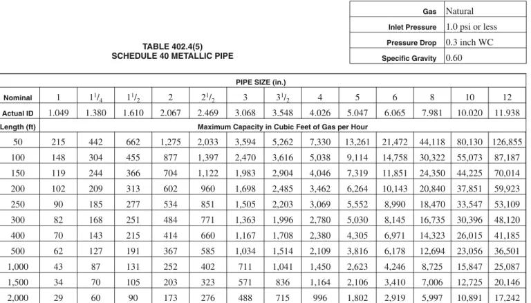
For SI: 1 inch = 25.4 mm, 1 foot = 304.8 mm, 1 cubic foot per hour = 0.0283 m3/h, 1 pound per square inch = 6.895 kPa, 1-inch water column = 0.2488 kPa. TABLE 402.4(5)
SCHEDULE 40 METALLIC PIPE
Gas Natural Inlet Pressure 1.0 psi or less Pressure Drop 0.3 inch WC Specific Gravity 0.60 PIPE SIZE (in.)
Nominal 1 11/
4 11/2 2 21/2 3 31/2 4 5 6 8 10 12
Actual ID 1.049 1.380 1.610 2.067 2.469 3.068 3.548 4.026 5.047 6.065 7.981 10.020 11.938 Length (ft) Maximum Capacity in Cubic Feet of Gas per Hour
50 215 442 662 1,275 2,033 3,594 5,262 7,330 13,261 21,472 44,118 80,130 126,855 100 148 304 455 877 1,397 2,470 3,616 5,038 9,114 14,758 30,322 55,073 87,187 150 119 244 366 704 1,122 1,983 2,904 4,046 7,319 11,851 24,350 44,225 70,014 200 102 209 313 602 960 1,698 2,485 3,462 6,264 10,143 20,840 37,851 59,923 250 90 185 277 534 851 1,505 2,203 3,069 5,552 8,990 18,470 33,547 53,109 300 82 168 251 484 771 1,363 1,996 2,780 5,030 8,145 16,735 30,396 48,120 400 70 143 215 414 660 1,167 1,708 2,380 4,305 6,971 14,323 26,015 41,185 500 62 127 191 367 585 1,034 1,514 2,109 3,816 6,178 12,694 23,056 36,501 1,000 43 87 131 252 402 711 1,041 1,450 2,623 4,246 8,725 15,847 25,087 1,500 34 70 105 203 323 571 836 1,164 2,106 3,410 7,006 12,725 20,146 2,000 29 60 90 173 276 488 715 996 1,802 2,919 5,997 10,891 17,242
GAS PIPING INSTALLATIONS
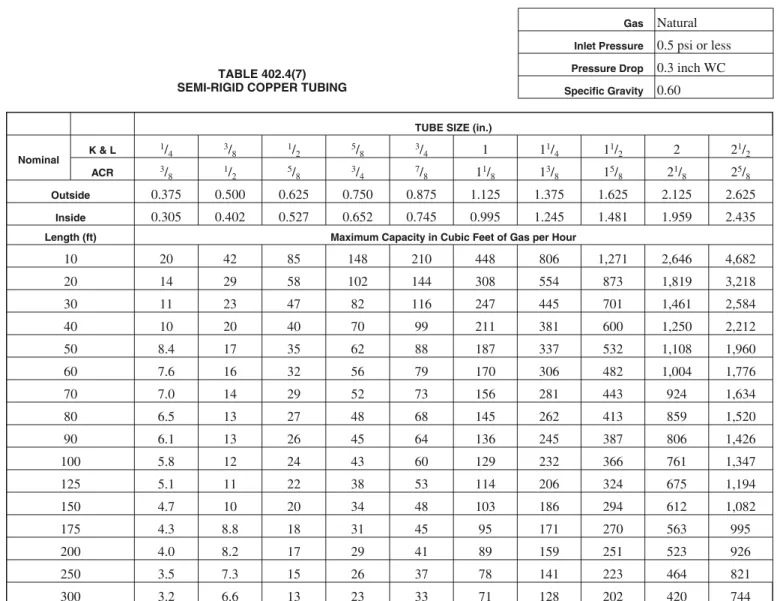
TABLE 402.4(7) SEMI-RIGID COPPER TUBING
Gas Natural Inlet Pressure 0.5 psi or less Pressure Drop 0.3 inch WC Specific Gravity 0.60
TUBE SIZE (in.)
Nominal K & L 1/ 4 3/8 1/2 5/8 3/4 1 11/4 11/2 2 21/2 ACR 3/8 1/2 5/8 3/4 7/8 11/8 13/8 15/8 21/8 25/8 Outside 0.375 0.500 0.625 0.750 0.875 1.125 1.375 1.625 2.125 2.625 Inside 0.305 0.402 0.527 0.652 0.745 0.995 1.245 1.481 1.959 2.435
Length (ft) Maximum Capacity in Cubic Feet of Gas per Hour
10 20 42 85 148 210 448 806 1,271 2,646 4,682 20 14 29 58 102 144 308 554 873 1,819 3,218 30 11 23 47 82 116 247 445 701 1,461 2,584 40 10 20 40 70 99 211 381 600 1,250 2,212 50 8.4 17 35 62 88 187 337 532 1,108 1,960 60 7.6 16 32 56 79 170 306 482 1,004 1,776 70 7.0 14 29 52 73 156 281 443 924 1,634 80 6.5 13 27 48 68 145 262 413 859 1,520 90 6.1 13 26 45 64 136 245 387 806 1,426 100 5.8 12 24 43 60 129 232 366 761 1,347 125 5.1 11 22 38 53 114 206 324 675 1,194 150 4.7 10 20 34 48 103 186 294 612 1,082 175 4.3 8.8 18 31 45 95 171 270 563 995 200 4.0 8.2 17 29 41 89 159 251 523 926 250 3.5 7.3 15 26 37 78 141 223 464 821 300 3.2 6.6 13 23 33 71 128 202 420 744
Note: Table capacities are based on Type K copper tubing inside diameter (shown), which has the smallest inside diameter of the copper tubing products. For SI: 1 inch = 25.4 mm, 1 foot = 304.8 mm, 1 cubic foot per hour = 0.0283 m3/h, 1 pound per square inch = 6.895 kPa, 1-inch water column = 0.2488 kPa.
GAS PIPING INSTALLATIONS
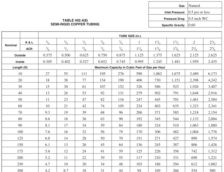
TABLE 402.4(8) SEMI-RIGID COPPER TUBING
Gas Natural Inlet Pressure 0.5 psi or less Pressure Drop 0.5 inch WC Specific Gravity 0.60
TUBE SIZE (in.)
Nominal K & L 1/ 4 3/8 1/2 5/8 3/4 1 11/4 11/2 2 21/2 ACR 3/8 1/2 5/8 3/4 7/8 11/8 13/8 15/8 21/8 25/8 Outside 0.375 0.500 0.625 0.750 0.875 1.125 1.375 1.625 2.125 2.625 Inside 0.305 0.402 0.527 0.652 0.745 0.995 1.245 1.481 1.959 2.435
Length (ft) Maximum Capacity in Cubic Feet of Gas per Hour
10 27 55 111 195 276 590 1,062 1,675 3,489 6,173 20 18 38 77 134 190 406 730 1,151 2,398 4,242 30 15 30 61 107 152 326 586 925 1,926 3,407 40 13 26 53 92 131 279 502 791 1,648 2,916 50 11 23 47 82 116 247 445 701 1,461 2,584 60 10 21 42 74 105 224 403 635 1,323 2,341 70 9.3 19 39 68 96 206 371 585 1,218 2,154 80 8.6 18 36 63 90 192 345 544 1,133 2,004 90 8.1 17 34 59 84 180 324 510 1,063 1,880 100 7.6 16 32 56 79 170 306 482 1,004 1,776 125 6.8 14 28 50 70 151 271 427 890 1,574 150 6.1 13 26 45 64 136 245 387 806 1,426 175 5.6 12 24 41 59 125 226 356 742 1,312 200 5.2 11 22 39 55 117 210 331 690 1,221 250 4.7 10 20 34 48 103 186 294 612 1,082 300 4.2 8.7 18 31 44 94 169 266 554 980
Note: Table capacities are based on Type K copper tubing inside diameter (shown), which has the smallest inside diameter of the copper tubing products. For SI: 1 inch = 25.4 mm, 1 foot = 304.8 mm, 1 cubic foot per hour = 0.0283 m3/h, 1 pound per square inch = 6.895 kPa, 1-inch water column = 0.2488 kPa.
301.15 Prohibited location.The appliances, equipment and systems regulated by this code shall not be located in an eleva-tor shaft.
SECTION 302 (IFGC) STRUCTURAL SAFETY
[B] 302.1 Structural safety.The building shall not be weak-ened by the installation of any gas piping. In the process of in-stalling or repairing any gas piping, the finished floors, walls, ceilings, tile work or any other part of the building or premises which is required to be changed or replaced shall be left in a safe structural condition in accordance with the requirements of theInternational Building Code.
[B] 302.2 Penetrations of floor/ceiling assemblies and fire-resistance-rated assemblies.Penetrations of floor/ceil-ing assemblies and assemblies required to have a fire-resis-tance rating shall be protected in accordance with the International Building Code.
[B] 302.3 Cutting, notching and boring in wood members. The cutting, notching and boring of wood members shall com-ply with Sections 302.3.1 through 302.3.4.
[B] 302.3.1 Engineered wood products.Cuts, notches and holes bored in trusses, laminated veneer lumber, glued-lam-inated members and I-joists are prohibited except where the effects of such alterations are specifically considered in the design of the member.
[B] 302.3.2 Joist notching.Notching at the ends of joists shall not exceed one-fourth the joist depth. Holes bored in joists shall not be within 2 inches (51 mm) of the top and bottom of the joist and their diameter shall not exceed one-third the depth of the member. Notches in the top or bot-tom of the joist shall not exceed one-sixth the depth and shall not be located in the middle one-third of the span. [B] 302.3.3 Stud cutting and notching.In exterior walls and bearing partitions, any wood stud is permitted to be cut or notched to a depth not exceeding 25 percent of its width. Cutting or notching of studs to a depth not greater than 40 percent of the width of the stud is permitted in nonload-bearing partitions supporting no loads other than the weight of the partition.
[B] 302.3.4 Bored holes.A hole not greater in diameter than 40 percent of the stud depth is permitted to be bored in any wood stud. Bored holes not greater than 60 percent of the depth of the stud are permitted in nonload-bearing partitions or in any wall where each bored stud is doubled, provided not more than two such successive doubled studs are so bored. In no case shall the edge of the bored hole be nearer than5/
8inch (15.9 mm) to the edge of the stud. Bored holes shall not be located at the same section of stud as a cut or notch.
[B] 302.4 Alterations to trusses.Truss members and compo-nents shall not be cut, drilled, notched, spliced or otherwise al-tered in any way without the written concurrence and approval of a registered design professional. Alterations resulting in the addition of loads to any member (e.g., HVAC equipment, water heaters) shall not be permitted without verification that the truss is capable of supporting such additional loading.
[B] 302.5 Cutting, notching and boring holes in structural steel framing.The cutting, notching and boring of holes in structural steel framing members shall be as prescribed by the registered design professional.
[B] 302.6 Cutting, notching and boring holes in cold-formed steel framing.Flanges and lips of load-bearing, cold-formed steel framing members shall not be cut or notched. Holes in webs of load-bearing, cold-formed steel framing members shall be permitted along the centerline of the web of the framing member and shall not exceed the dimensional limi-tations, penetration spacing or minimum hole edge distance as prescribed by the registered design professional. Cutting, notching and boring holes of steel floor/roof decking shall be as prescribed by the registered design professional.
[B] 302.7 Cutting, notching and boring holes in nonstructural cold-formed steel wall framing.Flanges and lips of nonstructural cold-formed steel wall studs shall be per-mitted along the centerline of the web of the framing member, shall not exceed 11/
2inches (38 mm) in width or 4 inches (102 mm) in length, and the holes shall not be spaced less than 24 inches (610 mm) center to center from another hole or less than 10 inches (254 mm) from the bearing end.
SECTION 303 (IFGC) APPLIANCE LOCATION
303.1 General.Appliances shall be located as required by this section, specific requirements elsewhere in this code and the conditions of the equipment and appliance listing.
303.2 Hazardous locations.Appliances shall not be located in a hazardous location unless listed and approved for the specific installation.
303.3 Prohibited locations.Appliances shall not be located in, or obtain combustion air from, any of the following rooms or spaces: 1. Sleeping rooms. 2. Bathrooms. 3. Toilet rooms. 4. Storage closets. 5. Surgical rooms. Exceptions:
1. Direct-vent appliances that obtain all combustion air directly from the outdoors.
2. Vented room heaters, wall furnaces, vented decorative appliances and decorative appliances for installation in vented solid fuel-burning fireplaces, provided that the room meets the required volume criteria of Sec-tion 304.5.
3. A single wall-mounted unvented room heater equipped with an oxygen depletion safety shutoff sys-tem and installed in a bathroom, provided that the in-put rating does not exceed 6,000 Btu/h (1.76kW) and the bathroom meets the required volume criteria of Section 304.5.
4. A single wall-mounted unvented room heater equipped with an oxygen depletion safety shutoff
tem and installed in a bedroom, provided that the in-put rating does not exceed 10,000 Btu/h (2.93 kW) and the bedroom meets the required volume criteria of Section 304.5.
5. Appliances installed in an enclosure in which all com-bustion air is taken from the outdoors, in accordance with Section 304.6. Access to such enclosure shall be through a solid weather-stripped door, equipped with an approved self-closing device.
303.4 Protection from physical damage.Appliances shall not be installed in a location where subject to physical damage un-less protected by approved barriers meeting the requirements of theInternational Fire Code.
303.5 Indoor locations.Furnaces and boilers installed in clos-ets and alcoves shall be listed for such installation.
303.6 Outdoor locations.Equipment installed in outdoor lo-cations shall be either listed for outdoor installation or provided with protection from outdoor environmental factors that influ-ence the operability, durability and safety of the equipment. 303.7 Pit locations.Appliances installed in pits or excavations shall not come in direct contact with the surrounding soil. The sides of the pit or excavation shall be held back a minimum of 12 inches (305 mm) from the appliance. Where the depth ex-ceeds 12 inches (305 mm) below adjoining grade, the walls of the pit or excavation shall be lined with concrete or masonry, such concrete or masonry shall extend a minimum of 4 inches (102 mm) above adjoining grade and shall have sufficient lat-eral load-bearing capacity to resist collapse. The appliance shall be protected from flooding in an approved manner.
SECTION 304 (IFGS)
COMBUSTION, VENTILATION AND DILUTION AIR 304.1 General.Air for combustion, ventilation and dilution of flue gases for gas utilization equipment installed in buildings shall be provided by application of one of the methods pre-scribed in Sections 304.5 through 304.9. Where the require-ments of Section 304.5 are not met, outdoor air shall be introduced in accordance with one of the methods prescribed in Sections 304.6 through 304.9. Direct-vent appliances, gas ap-pliances of other than natural draft design and vented gas appli-ances other than Category I shall be provided with combustion, ventilation and dilution air in accordance with the equipment manufacturer’s instructions.
Exception: Type 1 clothes dryers that are provided with makeup air in accordance with Section 614.5.
304.2 Appliance/equipment location.Equipment shall be lo-cated so as not to interfere with proper circulation of combus-tion, ventilation and dilution air.
304.3 Draft hood/regulator location. Where used, a draft hood or a barometric draft regulator shall be installed in the same room or enclosure as the equipment served so as to pre-vent any difference in pressure between the hood or regulator and the combustion air supply.
304.4 Makeup air provisions.Makeup air requirements for the operation of exhaust fans, kitchen ventilation systems,
clothes dryers and fireplaces shall be considered in determining the adequacy of a space to provide combustion air requirements. 304.5 Indoor combustion air.The required volume of indoor air shall be determined in accordance with Section 304.5.1 or 304.5.2, except that where the air infiltration rate is known to be less than 0.40 air changes per hour (ACH), Section 304.5.2 shall be used. The total required volume shall be the sum of the required volume calculated for all appliances located within the space. Rooms communicating directly with the space in which the appliances are installed through openings not fur-nished with doors, and through combustion air openings sized and located in accordance with Section 304.5.3, are considered to be part of the required volume.
304.5.1 Standard method.The minimum required volume shall be 50 cubic feet per 1,000 Btu/h (4.8 m3/kW) of the ap-pliance input rating.
304.5.2 Known air-infiltration-rate method. Where the air infiltration rate of a structure is known, the minimum re-quired volume shall be determined as follows:
For appliances other than fan-assisted, calculate volume using Equation 3-1.
Required Volumeother≥
21 1 000 3 ft ACH I B u hr other , t / (Equation 3-1) For fan-assisted appliances, calculate volume using Equation 3-2.
Required Volumefan≥
15 1 000 3 ft ACH I B u hr fan , t / (Equation 3-2) where:
Iother = All appliances other than fan assisted (input in
Btu/h).
Ifan = Fan-assisted appliance (input in Btu/h).
ACH = Air change per hour (percent of volume of space exchanged per hour, expressed as a decimal). For purposes of this calculation, an infiltration rate greater than 0.60 ACH shall not be used in Equations 3-1 and 3-2.
304.5.3 Indoor opening size and location.Openings used to connect indoor spaces shall be sized and located in accor-dance with Sections 304.5.3.1 and 304.5.3.2 (see Figure 304.5.3).
304.5.3.1 Combining spaces on the same story.Each opening shall have a minimum free area of 1 square inch per 1,000 Btu/h (2,200 mm2/kW) of the total input rating of all gas utilization equipment in the space, but not less than 100 square inches (0.06 m2). One opening shall commence within 12 inches (305 mm) of the top and one opening shall commence within 12 inches (305 mm) of the bottom of the enclosure. The minimum dimension of air openings shall be not less than 3 inches (76 mm). 304.5.3.2 Combining spaces in different stories.The volumes of spaces in different stories shall be considered as communicating spaces where such spaces are
con-GENERAL REGULATIONS
á
nected by one or more openings in doors or floors having a total minimum free area of 2 square inches per 1,000 Btu/h (4402 mm2/kW) of total input rating of all gas utili-zation equipment.
304.6 Outdoor combustion air.Outdoor combustion air shall be provided through opening(s) to the outdoors in accordance with Section 304.6.1 or 304.6.2. The minimum dimension of air openings shall be not less than 3 inches (76 mm).
304.6.1 Two-permanent-openings method. Two perma-nent openings, one commencing within 12 inches (305 mm) of the top and one commencing within 12 inches (305 mm) of the bottom of the enclosure, shall be provided. The open-ings shall communicate directly, or by ducts, with the out-doors or spaces that freely communicate with the outout-doors.
Where directly communicating with the outdoors, or where communicating with the outdoors through vertical ducts, each opening shall have a minimum free area of 1 square inch per 4,000 Btu/h (550 mm2/kW) of total input rating of all equipment in the enclosure [see Figures 304.6.1(1) and 304.6.1(2)].
Where communicating with the outdoors through hori-zontal ducts, each opening shall have a minimum free area of not less than 1 square inch per 2,000 Btu/h (1,100 mm2/kW) of total input rating of all equipment in the enclo-sure [see Figure 304.6.1(3)].
304.6.2 One-permanent-opening method. One perma-nent opening, commencing within 12 inches (305 mm) of the top of the enclosure, shall be provided. The equipment shall have clearances of at least 1 inch (25 mm) from the sides and back and 6 inches (152 mm) from the front of the appliance. The opening shall directly communicate with the outdoors or through a vertical or horizontal duct to the out-doors or spaces that freely communicate with the outout-doors [see Figure 304.6.2] and shall have a minimum free area of 1 square inch per 3,000 Btu/h (734 mm2/kW) of the total input rating of all equipment located in the enclosure, and not less than the sum of the areas of all vent connectors in the space. 304.7 Combination indoor and outdoor combustion air. The use of a combination of indoor and outdoor combustion air shall be in accordance with Sections 304.7.1 through 304.7.3.
304.7.1 Indoor openings.Where used, openings connect-ing the interior spaces shall comply with Section 304.5.3. 304.7.2 Outdoor opening location. Outdoor opening(s) shall be located in accordance with Section 304.6.
304.7.3 Outdoor opening(s) size.The outdoor opening(s) size shall be calculated in accordance with the following:
1. The ratio of interior spaces shall be the available vol-ume of all communicating spaces divided by the re-quired volume.
2. The outdoor size reduction factor shall be one minus the ratio of interior spaces.
3. The minimum size of outdoor opening(s) shall be the full size of outdoor opening(s) calculated in accor-dance with Section 304.6, multiplied by the reduction factor. The minimum dimension of air openings shall be not less than 3 inches (76 mm).
304.8 Engineered installations.Engineered combustion air installations shall provide an adequate supply of combustion, ventilation and dilution air and shall be approved.
304.9 Mechanical combustion air supply.Where all combus-tion air is provided by a mechanical air supply system, the com-bustion air shall be supplied from the outdoors at a rate not less than 0.35 cubic feet per minute per 1,000 Btu/h (0.034 m3/min per kW) of total input rating of all appliances located within the space.
304.9.1 Makeup air. Where exhaust fans are installed, makeup air shall be provided to replace the exhausted air. 304.9.2 Appliance interlock.Each of the appliances served shall be interlocked with the mechanical air supply system to prevent main burner operation when the mechanical air supply system is not in operation.
304.9.3 Combined combustion air and ventilation air system.Where combustion air is provided by the building’s mechanical ventilation system, the system shall provide the specified combustion air rate in addition to the required ven-tilation air.
304.10 Louvers and grilles.The required size of openings for combustion, ventilation and dilution air shall be based on the net free area of each opening. Where the free area through a de-sign of louver or grille is known, it shall be used in calculating the size opening required to provide the free area specified. Where the design and free area are not known, it shall be as-sumed that wood louvers will have 25-percent free area and metal louvers and grilles will have 75-percent free area. Nonmotorized louvers and grilles shall be fixed in the open po-sition. Motorized louvers shall be interlocked with the equip-ment so that they are proven to be in the full open position prior to main burner ignition and during main burner operation. Means shall be provided to prevent the main burner from ignit-ing if the louvers fail to open durignit-ing burner start-up and to shut down the main burner if the louvers close during operation. 304.11 Combustion air ducts. Combustion air ducts shall comply with all of the following:
1. Ducts shall be of galvanized steel complying with Chap-ter 6 of theInternational Mechanical Codeor of equiva-lent corrosion-resistant material approved for this application.
Exception:Within dwellings units, unobstructed stud and joist spaces shall not be prohibited from convey-ing combustion air, provided that not more than one required fireblock is removed.
2. Ducts shall terminate in an unobstructed space allowing free movement of combustion air to the appliances. 3. Ducts shall serve a single enclosure.
4. Ducts shall not serve both upper and lower combustion air openings where both such openings are used. The sep-aration between ducts serving upper and lower combus-tion air openings shall be maintained to the source of combustion air.
5. Ducts shall not be screened where terminating in an attic space.
GENERAL REGULATIONS
6. Horizontal upper combustion air ducts shall not slope downward toward the source of combustion air. 7. The remaining space surrounding a chimney liner, gas
vent, special gas vent or plastic piping installed within a masonry, metal or factory-built chimney shall not be used to supply combustion air.
Exception: Direct-vent gas-fired appliances de-signed for installation in a solid fuel-burning fireplace where installed in accordance with the listing and the manufacturer’s instructions.
8. Combustion air intake openings located on the exterior of a building shall have the lowest side of such openings lo-cated not less than 12 inches (305 mm) vertically from the adjoining grade level.
304.12 Protection from fumes and gases.Where corrosive or flammable process fumes or gases, other than products of com-bustion, are present, means for the disposal of such fumes or gases shall be provided. Such fumes or gases include carbon monoxide, hydrogen sulfide, ammonia, chlorine and halogenated hydrocarbons.
In barbershops, beauty shops and other facilities where chemicals that generate corrosive or flammable products, such as aerosol sprays, are routinely used, nondirect-vent-type ap-pliances shall be located in an equipment room separated or partitioned off from other areas with provisions for combustion air and dilution air from the outdoors. Direct-vent appliances shall be installed in accordance with the appliance manufac-turer's installation instructions.
GENERAL REGULATIONS
FIGURE 304.5.3
ALL AIR FROM INSIDE THE BUILDING (see Section 304.5.3)
FIGURE 304.6.1(1)
ALL AIR FROM OUTDOORS—INLET AIR FROM VENTILATED CRAWL SPACE AND OUTLET AIR TO VENTILATED ATTIC
(see Section 304.6.1)
FIGURE 304.6.1(2)
ALL AIR FROM OUTDOORS THROUGH VENTILATED ATTIC (see Section 304.6.1)
SECTION 305 (IFGC) INSTALLATION
305.1 General.Equipment and appliances shall be installed as required by the terms of their approval, in accordance with the conditions of listing, the manufacturer’s instructions and this code. Manufacturers’ installation instructions shall be avail-able on the job site at the time of inspection. Where a code pro-vision is less restrictive than the conditions of the listing of the equipment or appliance or the manufacturer’s installation in-structions, the conditions of the listing and the manufacturer’s installation instructions shall apply.
Unlisted appliances approved in accordance with Section 301.3 shall be limited to uses recommended by the turer and shall be installed in accordance with the manufac-turer’s instructions, the provisions of this code and the requirements determined by the code official.
305.2 Hazardous area.Equipment and appliances having an ignition source shall not be installed in Group H occupancies or control areas where open use, handling or dispensing of com-bustible, flammable or explosive materials occurs.
305.3 Elevation of ignition source.Equipment and appliances having an ignition source shall be elevated such that the source of ignition is not less than 18 inches (457 mm) above the floor in hazardous locations and public garages, private garages, re-pair garages, motor fuel-dispensing facilities and parking ga-rages. For the purpose of this section, rooms or spaces that are not part of the living space of a dwelling unit and that communi-cate directly with a private garage through openings shall be considered to be part of the private garage.
Exception:Elevation of the ignition source is not required for appliances that are listed as flammable vapor resistant and for installation without elevation.
305.4 Public garages.Appliances located in public garages, motor fuel-dispensing facilities, repair garages or other areas frequented by motor vehicles shall be installed a minimum of 8 feet (2438 mm) above the floor. Where motor vehicles exceed 6 feet (1829 mm) in height and are capable of passing under an appliance, appliances shall be installed a minimum of 2 feet (610 mm) higher above the floor than the height of the tallest vehicle.
Exception:The requirements of this section shall not apply where the appliances are protected from motor vehicle im-pact and installed in accordance with Section 305.3 and NFPA 88B.
305.5 Private garages.Appliances located in private garages shall be installed with a minimum clearance of 6 feet (1829 mm) above the floor.
Exception:The requirements of this section shall not apply where the appliances are protected from motor vehicle im-pact and installed in accordance with Section 305.3. 305.6 Construction and protection.Boiler rooms and furnace rooms shall be protected as required by theInternational Build-ing Code.
305.7 Clearances from grade.Equipment and appliances in-stalled at grade level shall be supported on a level concrete slab or other approved material extending above adjoining grade or shall be suspended a minimum of 6 inches (152 mm) above ad-joining grade.
305.8 Clearances to combustible construction. Heat-produc-ing equipment and appliances shall be installed to maintain the required clearances to combustible construction as specified in the listing and manufacturer’s instructions. Such clearances shall be reduced only in accordance with Section 308. Clear-ances to combustibles shall include such considerations as door swing, drawer pull, overhead projections or shelving and win-dow swing. Devices, such as door stops or limits and closers, shall not be used to provide the required clearances.
GENERAL REGULATIONS
FIGURE 304.6.1(3) ALL AIR FROM OUTDOORS
(see Section 304.6.1)
FIGURE 304.6.2
SINGLE COMBUSTION AIR OPENING, ALL AIR FROM THE OUTDOORS
SECTION 306 (IFGC) ACCESS AND SERVICE SPACE
[M] 306.1 Clearances for maintenance and replacement. Clearances around appliances to elements of permanent con-struction, including other installed appliances, shall be suffi-cient to allow inspection, service, repair or replacement without removing such elements of permanent construction or disabling the function of a required fire-resistance-rated as-sembly.
[M] 306.2 Appliances in rooms.Rooms containing appliances requiring access shall be provided with a door and an unob-structed passageway measuring not less than 36 inches (914 mm) wide and 80 inches (2032 mm) high.
Exception:Within a dwelling unit, appliances installed in a compartment, alcove, basement or similar space shall be provided with access by an opening or door and an unob-structed passageway measuring not less than 24 inches (610 mm) wide and large enough to allow removal of the largest appliance in the space, provided that a level service space of not less than 30 inches (762 mm) deep and the height of the appliance, but not less than 30 inches (762 mm), is present at the front or service side of the appliance with the door open. [M] 306.3 Appliances in attics.Attics containing appliances requiring access shall be provided with an opening and unob-structed passageway large enough to allow removal of the larg-est component of the appliance. The passageway shall not be less than 30 inches (762 mm) high and 22 inches (559 mm) wide and not more than 20 feet (6096 mm) in length when mea-sured along the centerline of the passageway from the opening to the equipment. The passageway shall have continuous solid flooring not less than 24 inches (610 mm) wide. A level service space not less than 30 inches (762 mm) deep and 30 inches (762 mm) wide shall be present at the front or service side of the equipment. The clear access opening dimensions shall be a minimum of 20 inches by 30 inches (508 mm by 762 mm), where such dimensions are large enough to allow removal of the largest component of the appliance.
Exceptions:
1. The passageway and level service space are not re-quired where the appliance is capable of being ser-viced and removed through the required opening. 2. Where the passageway is not less than 6 feet (1829
mm) high for its entire length, the passageway shall be not greater than 50 feet (15 250 mm) in length. [M] 306.3.1 Electrical requirements.A lighting fixture con-trolled by a switch located at the required passageway opening and a receptacle outlet shall be provided at or near the equip-ment location in accordance with the ICCElectrical Code. [M] 306.4 Appliances under floors.Under-floor spaces con-taining appliances requiring access shall be provided with an access opening and unobstructed passageway large enough to remove the largest component of the appliance. The passage-way shall not be less than 30 inches (762 mm) high and 22 inches (559 mm) wide, nor more than 20 feet (6096 mm) in length when measured along the centerline of the passageway from the opening to the equipment. A level service space not less than 30 inches (762 mm) deep and 30 inches (762 mm)
wide shall be present at the front or service side of the appliance. If the depth of the passageway or the service space exceeds 12 inches (305 mm) below the adjoining grade, the walls of the passageway shall be lined with concrete or ma-sonry extending 4 inches (102 mm) above the adjoining grade and having sufficient lateral-bearing capacity to resist collapse. The clear access opening dimensions shall be a minimum of 22 inches by 30 inches (559 mm by 762 mm), where such dimen-sions are large enough to allow removal of the largest compo-nent of the appliance.
Exceptions:
1. The passageway is not required where the level ser-vice space is present when the access is open and the appliance is capable of being serviced and removed through the required opening.
2. Where the passageway is not less than 6 feet high (1829 mm) for its entire length, the passageway shall not be limited in length.
[M] 306.4.1 Electrical requirements.A lighting fixture con-trolled by a switch located at the required passageway opening and a receptacle outlet shall be provided at or near the equip-ment location in accordance with the ICCElectrical Code. [M] 306.5 Appliances on roofs or elevated structures.Where appliances requiring access are installed on roofs or elevated structures at a height exceeding 16 feet (4877 mm), such access shall be provided by a permanent approved means of access, the extent of which shall be from grade or floor level to the ap-pliance’s level service space. Such access shall not require climbing over obstructions greater than 30 inches high (762 mm) or walking on roofs having a slope greater than four units vertical in 12 units horizontal (33-percent slope).
Permanent ladders installed to provide the required access shall comply with the following minimum design criteria.
1. The side railing shall extend above the parapet or roof edge not less than 30 inches (762 mm).
2. Ladders shall have a rung spacing not to exceed 14 inches (356 mm) on center.
3. Ladders shall have a toe spacing not less than 6 inches (152 mm) deep.
4. There shall be a minimum of 18 inches (457 mm) be-tween rails.
5. Rungs shall have a minimum diameter of 0.75-inch (19 mm) and shall be capable of withstanding a 300-pound (136.1 kg) load.
6. Ladders over 30 feet (9144 mm) in height shall be pro-vided with offset sections and landings capable of with-standing a load of 100 pounds per square foot (488.2 kg/m2).
7. Ladders shall be protected against corrosion by approved means.
Catwalks installed to provide the required access shall be not less than 24 inches wide (610 mm) and shall have railings as re-quired for service platforms.
Exception:This section shall not apply to Group R-3 occu-pancies.
[M] 306.5.1 Sloped roofs.Where appliances are installed on a roof having a slope of three units vertical in 12 units horizontal (25-percent slope) or greater and having an edge more than 30 inches (762 mm) above grade at such edge, a level platform shall be provided on each side of the appli-ance to which access is required by the manufacturer’s in-stallation instructions for service, repair or maintenance. The platform shall not be less than 30 inches (762 mm) in any dimension and shall be provided with guards in accor-dance with Section 306.6.
[M] 306.5.2 Electrical requirements.A receptacle outlet shall be provided at or near the equipment location in accor-dance with the ICCElectrical Code.
[M] 306.6 Guards. Guards shall be provided where appli-ances, fans or other components that require service are located within 10 feet (3048 mm) of a roof edge or open side of a walk-ing surface and such edge or open side is located more than 30 inches (762 mm) above the floor, roof or grade below. The guard shall extend not less than 30 inches (762 mm) beyond each end of such appliances, fans or other components and the top of the guard shall be located not less than 42 inches (1067 mm) above the elevated surface adjacent to the guard. The guard shall be constructed so as to prevent the passage of a 21-inch-diameter (533 mm) sphere and shall comply with the loading requirements for guards specified in theInternational Building Code.
SECTION 307 (IFGC) CONDENSATE DISPOSAL
307.1 Fuel-burning appliances.Liquid combustion by-prod-ucts of condensing appliances shall be collected and dis-charged to an approved plumbing fixture or disposal area in accordance with the manufacturer’s installation instructions. Condensate piping shall be of approved corrosion-resistant material and shall not be smaller than the drain connection on the appliance. Such piping shall maintain a minimum slope in the direction of discharge of not less than one-eighth unit verti-cal in 12 units horizontal (1-percent slope).
[M] 307.2 Drain pipe materials and sizes.Components of the condensate disposal system shall be cast iron, galvanized steel, copper, polybutylene, polyethylene, ABS, CPVC or PVC pipe or tubing. All components shall be selected for the pressure and temperature rating of the installation. Condensate waste and drain line size shall be not less than3/
4-inch internal diameter (19 mm) and shall not decrease in size from the drain connec-tion to the place of condensate disposal. Where the drain pipes from more than one unit are manifolded together for conden-sate drainage, the pipe or tubing shall be sized in accordance with an approved method. All horizontal sections of drain pip-ing shall be installed in uniform alignment at a uniform slope. 307.3 Traps.Condensate drains shall be trapped as required by the equipment or appliance manufacturer.
SECTION 308 (IFGS) CLEARANCE REDUCTION
308.1 Scope.This section shall govern the reduction in re-quired clearances to combustible materials and combustible as-semblies for chimneys, vents, appliances, devices and equipment. Clearance requirements for air-conditioning equip-ment and central heating boilers and furnaces shall comply with Sections 308.3 and 308.4.
308.2 Reduction table. The allowable clearance reduction shall be based on one of the methods specified in Table 308.2 or shall utilize an assembly listed for such application. Where re-quired clearances are not listed in Table 308.2, the reduced clearances shall be determined by linear interpolation between the distances listed in the table. Reduced clearances shall not be derived by extrapolation below the range of the table. The re-duction of the required clearances to combustibles for listed and labeled appliances and equipment shall be in accordance with the requirements of this section except that such clear-ances shall not be reduced where reduction is specifically pro-hibited by the terms of the appliance or equipment listing [see Figures 308.2(1) through 308.2(3)].
308.3 Clearances for indoor air-conditioning equipment. Clearance requirements for indoor air-conditioning equipment shall comply with Sections 308.3.1 through 308.3.5.
308.3.1 Equipment installed in rooms that are large in comparison with the size of the equipment. Air-condi-tioning equipment installed in rooms that are large in com-parison with the size of the equipment shall be installed with clearances in accordance with the terms of their listing and the manufacturer’s instructions.
308.3.2 Equipment installed in rooms that are not large in comparison with the size of the equipment. Air-condi-tioning equipment installed in rooms that are not large in comparison with the size of the equipment, such as alcoves and closets, shall be listed for such installations and in-stalled in accordance with the manufacturer’s instructions. Listed clearances shall not be reduced by the protection methods described in Table 308.2, regardless of whether the enclosure is of combustible or noncombustible material. 308.3.3 Clearance reduction.Air-conditioning equipment installed in rooms that are large in comparison with the size of the equipment shall be permitted to be installed with re-duced clearances to combustible material provided the com-bustible material or equipment is protected as described in Table 308.2.
308.3.4 Plenum clearances.Where the furnace plenum is adjacent to plaster on metal lath or noncombustible material attached to combustible material, the clearance shall be measured to the surface of the plaster or other noncombustible finish where the clearance specified is 2 inches (51 mm) or less.
308.3.5 Clearance from supply ducts.Air-conditioning equipment shall have the clearance from supply ducts within 3 feet (914 mm) of the furnace plenum be not less than that specified from the furnace plenum. No clearance is necessary beyond this distance.
GENERAL REGULATIONS
TABLE 308.2a-k
REDUCTION OF CLEARANCES WITH SPECIFIED FORMS OF PROTECTION
TYPE OF PROTECTION APPLIED TO AND COVERING ALL SURFACES OF COMBUSTIBLE MATERIAL WITHIN THE DISTANCE SPECIFIED AS THE
REQUIRED CLEARANCE WITH NO PROTECTION [see Figures 308.2(1), 308.2(2), and 308.2(3)]
WHERE THE REQUIRED CLEARANCE WITH NO PROTECTION FROM APPLIANCE, VENT CONNECTOR, OR SINGLE-WALL METAL PIPE IS: (inches)
36 18 12 9 6
Allowable clearances with specified protection (inches)
Use Column 1 for clearances above appliance or horizontal connector. Use Column 2 for clearances from appliance, vertical connector, and single-wall metal pipe.
Above Col. 1 Sides and rear Col. 2 Above Col. 1 Sides and rear Col. 2 Above Col. 1 Sides and rear Col. 2 Above Col. 1 Sides and rear Col. 2 Above Col. 1 Sides and rear Col. 2 1. 31
/2-inch-thick masonry wall without ventilated airspace — 24 — 12 — 9 — 6 — 5
2. 1
/2-inch insulation board over 1-inch glass fiber or
mineral wool batts 24 18 12 9 9 6 6 5 4 3
3. 0.024 sheet metal over 1-inch glass fiber or mineral wool batts reinforced with wire on rear face with ventilated airspace
18 12 9 6 6 4 5 3 3 3
4. 31
/2-inch-thick masonry wall with ventilated airspace — 12 — 6 — 6 — 6 — 6
5. 0.024 sheet metal with ventilated airspace 18 12 9 6 6 4 5 3 3 2
6. 1
/2-inch-thick insulation board with ventilated airspace 18 12 9 6 6 4 5 3 3 3
7. 0.024 sheet metal with ventilated airspace over 0.024
sheet metal with ventilated airspace 18 12 9 6 6 4 5 3 3 3
8. 1-inch glass fiber or mineral wool batts sandwiched between two sheets 0.024 sheet metal with ventilated airspace
18 12 9 6 6 4 5 3 3 3
For SI: 1 inch = 25.4 mm, °C = [(°F - 32)/1.8], 1 pound per cubic foot = 16.02 kg/m3, 1 Btu per inch per square foot per hour per °F = 0.144 W/m2
⋅
K.a. Reduction of clearances from combustible materials shall not interfere with combustion air, draft hood clearance and relief, and accessibility of servicing. b. All clearances shall be measured from the outer surface of the combustible material to the nearest point on the surface of the appliance, disregarding any
interven-ing protection applied to the combustible material.
c. Spacers and ties shall be of noncombustible material. No spacer or tie shall be used directly opposite an appliance or connector.
d. For all clearance reduction systems using a ventilated airspace, adequate provision for air circulation shall be provided as described [see Figures 308.2(2) and 308.2(3)].
e. There shall be at least 1 inch between clearance reduction systems and combustible walls and ceilings for reduction systems using ventilated airspace. f. Where a wall protector is mounted on a single flat wall away from corners, it shall have a minimum 1-inch air gap. To provide air circulation, the bottom and top
edges, or only the side and top edges, or all edges shall be left open.
g. Mineral wool batts (blanket or board) shall have a minimum density of 8 pounds per cubic foot and a minimum melting point of 1500°F.
h. Insulation material used as part of a clearance reduction system shall have a thermal conductivity of 1.0 Btu per inch per square foot per hour per °F or less. i. There shall be at least 1 inch between the appliance and the protector. In no case shall the clearance between the appliance and the combustible surface be reduced
below that allowed in this table.
j. All clearances and thicknesses are minimum; larger clearances and thicknesses are acceptable.
308.4 Central-heating boilers and furnaces.Clearance re-quirements for central-heating boilers and furnaces shall com-ply with Sections 308.4.1 through 308.4.6. The clearance to this equipment shall not interfere with combustion air, draft hood clearance and relief, and accessibility for servicing.
308.4.1 Equipment installed in rooms that are large in comparison with the size of the equipment. Central-heat-ing furnaces and low-pressure boilers installed in rooms large in comparison with the size of the equipment shall be installed with clearances in accordance with the terms of their listing and the manufacturer’s instructions.
GENERAL REGULATIONS
For SI: 1 inch = 25.4 mm.
FIGURE 308.2(2)
WALL PROTECTOR CLEARANCE REDUCTION SYSTEM For SI: 1 inch = 25.4 mm.
FIGURE 308.2(3)
MASONRY CLEARANCE REDUCTION SYSTEM
“A” equals the reduced clearance with no protection.
“B” equals the reduced clearance permitted in accordance with Table 308.2. The protection applied to the construction using combustible material shall extend far enough in each direction to make “C” equal to “A.”
FIGURE 308.2(1)
EXTENT OF PROTECTION NECESSARY TO REDUCE CLEARANCES FROM GAS EQUIPMENT OR
308.4.2 Equipment installed in rooms that are not large in comparison with the size of the equipment. Central-heat-ing furnaces and low-pressure boilers installed in rooms that are not large in comparison with the size of the equipment, such as alcoves and closets, shall be listed for such installa-tions. Listed clearances shall not be reduced by the protection methods described in Table 308.2 and illustrated in Figures 308.2(1) through 308.2(3), regardless of whether the enclo-sure is of combustible or noncombustible material.
308.4.3 Clearance reduction. Central-heating furnaces and low-pressure boilers installed in rooms that are large in comparison with the size of the equipment shall be permit-ted to be installed with reduced clearances to combustible material provided the combustible material or equipment is protected as described in Table 308.2.
308.4.4 Clearance for servicing equipment.Front clear-ance shall be sufficient for servicing the burner and the fur-nace or boiler.
308.4.5 Plenum clearances.Where the furnace plenum is adjacent to plaster on metal lath or noncombustible material attached to combustible material, the clearance shall be measured to the surface of the plaster or other noncombustible finish where the clearance specified is 2 inches (51 mm) or less.
308.4.6 Clearance from supply ducts.Central-heating fur-naces shall have the clearance from supply ducts within 3 feet (914 mm) of the furnace plenum be not less than that specified from the furnace plenum. No clearance is neces-sary beyond this distance.
SECTION 309 (IFGC) ELECTRICAL
309.1 Grounding.Gas piping shall not be used as a grounding electrode.
309.2 Connections. Electrical connections between equip-ment and the building wiring, including the grounding of the equipment, shall conform to the ICCElectrical Code.
SECTION 310 (IFGS) ELECTRICAL BONDING
310.1 Gas pipe bonding.Each above-ground portion of a gas piping system that is likely to become energized shall be elec-trically continuous and bonded to an effective ground-fault cur-rent path. Gas piping shall be considered to be bonded where it is connected to gas utilization equipment that is connected to the equipment grounding conductor of the circuit supplying that equipment.
CHAPTER 4
GAS PIPING INSTALLATIONS
SECTION 401 (IFGC)GENERAL
401.1 Scope.This chapter shall govern the design, installation, modification and maintenance of piping systems. The applica-bility of this code to piping systems extends from the point of delivery to the connections with the equipment and includes the design, materials, components, fabrication, assembly, installa-tion, testing, inspecinstalla-tion, operation and maintenance of such piping systems.
401.1.1 Utility piping systems located within buildings. Utility service piping located within buildings shall be in-stalled in accordance with the structural safety and fire pro-tection provisions of theInternational Building Code. 401.2 Liquefied petroleum gas storage.The storage system for liquefied petroleum gas shall be designed and installed in accordance with theInternational Fire Codeand NFPA 58. 401.3 Modifications to existing systems.In modifying or add-ing to existadd-ing pipadd-ing systems, sizes shall be maintained in ac-cordance with this chapter.
401.4 Additional appliances.Where an additional appliance is to be served, the existing piping shall be checked to deter-mine if it has adequate capacity for all appliances served. If in-adequate, the existing system shall be enlarged as required or separate piping of adequate capacity shall be provided. 401.5 Identification.For other than black steel pipe, exposed piping shall be identified by a yellow label marked “Gas” in black letters. The marking shall be spaced at intervals not ex-ceeding 5 feet (1524 mm). The marking shall not be required on pipe located in the same room as the equipment served. 401.6 Interconnections. Where two or more meters are in-stalled on the same premises but supply separate consumers, the piping systems shall not be interconnected on the outlet side of the meters.
401.7 Piping meter identification.Piping from multiple me-ter installations shall be marked with an approved permanent identification by the installer so that the piping system supplied by each meter is readily identifiable.
401.8 Minimum sizes.All pipe utilized for the installation, ex-tension and alteration of any piping system shall be sized to supply the full number of outlets for the intended purpose and shall be sized in accordance with Section 402.
SECTION 402 (IFGS) PIPE SIZING
402.1 General considerations.Piping systems shall be of such size and so installed as to provide a supply of gas sufficient to meet the maximum demand without undue loss of pressure be-tween the point of delivery and the gas utilization equipment.
402.2 Maximum gas demand.The volume of gas to be pro-vided, in cubic feet per hour, shall be determined directly from the manufacturer’s input ratings of the gas utilization equip-ment served. Where an input rating is not indicated, the gas supplier, equipment manufacturer or a qualified agency shall be contacted, or the rating from Table 402.2 shall be used for estimating the volume of gas to be supplied.
The total connected hourly load shall be used as the basis for pipe sizing, assuming that all equipment could be operating at full capacity simultaneously. Where a diversity of load can be estab-lished, pipe sizing shall be permitted to be based on such loads.
TABLE 402.2
APPROXIMATE GAS INPUT FOR TYPICAL APPLIANCES APPLIANCE
INPUT BTU/H (Approx.)
Space Heating Units Hydronic boiler
Single family 100,000
Multifamily, per unit 60,000
Warm-air furnace
Single family 100,000
Multifamily, per unit 60,000
Space and Water Heating Units Hydronic boiler
Single family 120,000
Multifamily, per unit 75,000
Water Heating Appliances
Water heater, automatic instantaneous 35,000
Capacity at 2 gal./minute 50,000
Capacity at 4 gal./minute
Capacity at 6 gal./minute 142,800
Water heater, automatic storage, 30- to 40-gal. tank 285,000 Water heater, automatic storage, 50-gal. tank 428,400 Water heater, domestic, circulating or side-arm 35,000 Cooking Appliances
Built-in oven or broiler unit, domestic 65,000
Built-in top unit, domestic 25,000
Range, free-standing, domestic 40,000
Other Appliances
Barbecue 3,000
Clothes dryer, Type 1 (domestic) 35,000
Gas fireplace, direct vent 40,000
Gas light 80,000
Gas log 40,000
Refrigerator 2,500
For SI: 1 British thermal unit per hour = 0.293 W, 1 gallon = 3.785 L, 1 gallon per minute = 3.785 L/m.
402.3 Sizing.Gas piping shall be sized in accordance with one of the following:
1. Pipe sizing tables or sizing equations in accordance with Section 402.4.
2. The sizing tables included in a listed piping system’s manufacturer’s installation instructions.
3. Other approved engineering methods.
402.4 Sizing tables and equations. Where Tables 402.4(1) through 402.4(33) are used to size piping or tubing, the pipe length shall be determined in accordance with Section 402.4.1, 402.4.2 or 402.4.3.
Where Equations 4-1 and 4-2 are used to size piping or tub-ing, the pipe or tubing shall have smooth inside walls and the pipe length shall be determined in accordance with Section 402.4.1, 402.4.2 or 402.4.3.
1. Low-pressure gas equation [Less than 1.5 pounds per square inch (psi) (10.3 kPa)]:
D Q H Cr L = × 0 381 0 206 1917 . . . ∆ (Equation 4-1)
2. High-pressure gas equation [1.5 psi (10.3 kPa) and above]:
(
)
D Q P P Y Cr L = − × × 0 381 12 22 0 206 18 93 . . . (Equation 4-2) where:D = Inside diameter of pipe, inches (mm).
Q = Input rate appliance(s), cubic feet per hour at 60°F (16°C) and 30-inch mercury column
P1 = Upstream pressure, psia (P1+ 14.7) P2 = Downstream pressure, psia (P2+ 14.7) L = Equivalent length of pipe, feet
∆H = Pressure drop, inch water column (27.7 inch water col-umn = 1 psi)
TABLE 402.4
CrANDYVALUES FOR NATURAL GAS AND
UNDILUTED PROPANE AT STANDARD CONDITIONS
GAS
EQUATION FACTORS
Cr Y
Natural gas 0.6094 0.9992
Undiluted propane 1.2462 0.9910 For SI: 1 cubic foot = 0.028 m3, 1 foot = 305 mm, 1-inch water column =
0.249 kPa, 1 pound per square inch = 6.895 kPa, 1 British thermal unit per hour = 0.293 W.
402.4.1 Longest length method.The pipe size of each sec-tion of gas piping shall be determined using the longest length of piping from the point of delivery to the most re-mote outlet and the load of the section.
402.4.2 Branch length method.Pipe shall be sized as fol-lows:
1. Pipe size of each section of the longest pipe run from the point of delivery to the most remote outlet shall be determined using the longest run of piping and the load of the section.
2. The pipe size of each section of branch piping not pre-viously sized shall be determined using the length of piping from the point of delivery to the most remote outlet in each branch and the load of the section. 402.4.3 Hybrid pressure.The pipe size for each section of higher pressure gas piping shall be determined using the longest length of piping from the point of delivery to the most remote line pressure regulator. The pipe size from the line pressure regulator to each outlet shall be determined us-ing the length of pipus-ing from the regulator to the most re-mote outlet served by the regulator.
402.5 Allowable pressure drop.The design pressure loss in any piping system under maximum probable flow conditions, from the point of delivery to the inlet connection of the equip-ment, shall be such that the supply pressure at the equipment is greater than the minimum pressure required for proper equip-ment operation.
402.6 Maximum design operating pressure.The maximum design operating pressure for piping systems located inside buildings shall not exceed 5 pounds per square inch gauge (psig) (34 kPa gauge) except where one or more of the follow-ing conditions are met:
1. The piping system is welded.
2. The piping is located in a ventilated chase or otherwise enclosed for protection against accidental gas accumula-tion.
3. The piping is located inside buildings or separate areas of buildings used exclusively for:
3.1. Industrial processing or heating; 3.2. Research;
3.3. Warehousing; or
3.4. Boiler or mechanical equipment rooms. 4. The piping is a temporary installation for buildings under
construction.
402.6.1 Liquefied petroleum gas systems.The operating pressure for undiluted LP-gas systems shall not exceed 20 psig (140 kPa gauge). Buildings having systems designed to operate below -5°F (-21°C) or with butane or a propane-bu-tane mix shall be designed to either accommodate liquid LP-gas or prevent LP-gas vapor from condensing into a liq-uid.
Exception:Buildings or separate areas of buildings con-structed in accordance with Chapter 7 of NFPA 58, and used exclusively to house industrial processes, research and experimental laboratories, or equipment or process-ing havprocess-ing similar hazards.
GAS PIPING INSTALLATIONS
TABLE 402.4(1) SCHEDULE 40 METALLIC PIPE
Gas Natural Inlet Pressure 0.50 psi or less Pressure Drop 0.3 inch WC Specific Gravity 0.60 PIPE SIZE (in.)
Nominal 1/
4 3/8 1/2 3/4 1 11/4 11/2 2 21/2 3 4
Actual ID 0.364 0.493 0.622 0.824 1.049 1.380 1.610 2.067 2.469 3.068 4.026 Length (ft) Maximum Capacity in Cubic Feet of Gas per Hour
10 32 72 132 278 520 1,050 1,600 3,050 4,800 8,500 17,500 20 22 49 92 190 350 730 1,100 2,100 3,300 5,900 12,000 30 18 40 73 152 285 590 890 1,650 2,700 4,700 9,700 40 15 34 63 130 245 500 760 1,450 2,300 4,100 8,300 50 14 30 56 115 215 440 670 1,270 2,000 3,600 7,400 60 12 27 50 105 195 400 610 1,150 1,850 3,250 6,800 70 11 25 46 96 180 370 560 1,050 1,700 3,000 6,200 80 11 23 43 90 170 350 530 990 1,600 2,800 5,800 90 10 22 40 84 160 320 490 930 1,500 2,600 5,400 100 9 21 38 79 150 305 460 870 1,400 2,500 5,100 125 8 18 34 72 130 275 410 780 1,250 2,200 4,500 150 8 17 31 64 120 250 380 710 1,130 2,000 4,100 175 7 15 28 59 110 225 350 650 1,050 1,850 3,800 200 6 14 26 55 100 210 320 610 980 1,700 3,500
For SI: 1 inch = 25.4 mm, 1 foot = 304.8 mm, 1 cubic foot per hour = 0.0283 m3/h, 1 pound per square inch = 6.895 kPa, 1-inch water column = 0.2488 kPa.
TABLE 402.4(2) SCHEDULE 40 METALLIC PIPE
Gas Natural Inlet Pressure 0.50 psi or less Pressure Drop 0.5