Indoor Air Quality
A Guide to Understanding
Standard 62-2001, “Ventilation
for Acceptable Indoor Air
Quality.” It also advocates
system and equipment solutions
that meet the explicit and
suggested requirements of
that standard. We hope the
analysis provided here helps
professionals responsible for
designing, installing,
maintaining, and operating
of HVAC systems achieve
compliance with Standard 62.
that of the American Society of Heating, Refrigerating, and Air-Conditioning Engineers (ASHRAE). It also represents Trane’s interpretation of ASHRAE Standard 62-2001 which may or may not be the interpretation placed on it by others, including courts, called upon for such interpretation. Similarly, the
suggestions. Trane does not assume responsibility for the interpretation of this standard or for the performance or desirability of any system resulting from these suggestions. Responsibility for final system design—like interpretation and compliance with Standard 62—ultimately rests with the designer.
Table of Contents
Additional pieces of Trane
literature are referenced at
various points throughout this
document. This supplemental
information is available on the
Trane Bookstore at
www.trane.com/bookstore/or
from your local Trane office.
Page
Introduction
. . . .
3
Overview of ASHRAE Standard 62
. . .4
Terminology
. . .4
History of Standard 62
. . .4
How ASHRAE 62-2001 Addresses IAQ
. . .5
Fundamentals of Good Indoor Air Quality
. . .6
Contaminant Source Control
. . .6
Indoor Sources . . . 6
Sloped Drain Pans . . . 7
Cleanability . . . 8
Accessibility . . . 9
Outdoor Sources . . . .11
Proper Ventilation
. . . .12
Ventilation Rate Procedure . . . .13
Multi-Space Systems . . . 13
The VAV Ventilation Challenge . . . 13
Occupied vs. Unoccupied Ventilation . . . 14
Ventilation Effectiveness . . . 14
Intermittent Occupancy . . . 15
Preoccupancy Purge . . . 16
Summary of Ventilation Rate Procedure . . . 16
Indoor Air Quality Procedure . . . .16
Cleaning of Recirculated Air . . . 17
Summary of the IAQ Procedure . . . 17
Ventilation Control Strategies . . . .17
Ventilation Reset . . . 18
Scheduled Ventilation . . . 19
CO2-Based Demand-Controlled Ventilation . . . 19
Outdoor Airflow Measurement and Control . . . .21
Building Pressure Control . . . .23
Humidity Management
. . . .24
Constant Volume, Variable-Temperature Systems . . . .25
Variable-Air-Volume (VAV) Systems . . . .28
Humidity Control vs. Heat Recovery . . . .29
Filtration
. . . .30
Particulate Filtration . . . .30
Gaseous Filtration . . . .31
Summary
. . . .32
Addenda Incorporated into ASHRAE Standard 62-2001
. . . .33
to incorporate all approved addenda. The 2001 version incorporates twelve addenda that have been approved since 1989. The list of approved addenda and a brief description of the changes is included on page 32.
Ensuring compliance with applicable codes and standards within the economic context of each project challenges building design professionals to seek innovative HVAC equipment and system solutions. This guide attempts to clarify the ventilation, equipment, and system-related mandates in ASHRAE Standard 62-2001, and to identify practical, cost-effective solutions made possible by current technology. The material presented in this document reflects onlythe addenda approved when the 2001 version of the standard was printed.
renders indoor air quality (IAQ) a soft, highly subjective issue. But the fact is that poor IAQ reflects on everyone involved with the design, construction, operation, and maintenance of a building. “Sick” buildings hinder occupant productivity and discourage tenants from renewing their leases. In today’s litigious society, all parties need to be aware of the legal ramifications of an unhealthy indoor environment. ASHRAE Standard 62-2001 establishes the standard of carefor the design of commercial, institutional, and residential ventilation systems to “provide indoor air quality that will be acceptable to human occupants and is intended to minimize the potential for adverse health effects.” Building codes in most states reference Standard 62, either in part or in its entirety, as part of their definition of minimum ventilation requirements. As a “continuous maintenance” standard, Standard 62 is modified by
3
Air-Conditioning Engineers
(ASHRAE) comprises
representatives from all
vantages of the heating,
ventilation, refrigeration,
and air-conditioning (HVAC)
industry. Together, Society
members draft standards and
guidelines that provide counsel
on most aspects of HVAC system
selection, design, application,
commissioning, safety, and
operational criteria for a broad
spectrum of HVAC systems.
State and local authorities
frequently adopt these
standards and write them
into their codes.
To purchase a copy of
ASHRAE Standard 62-2001,
call 1-800-5 ASHRAE or visit
the online bookstore at
Overview of ASHRAE Standard 62
A building’s indoor air quality is the result of the decisions and actions of a wide variety of individuals over an extended period of time. Design of the building’s heating, ventilating, and air-conditioning system, contaminant sources, and air-cleaning efficiency all play roles, as do operation and maintenance of the building and its mechanical systems. Together, these variables make achieving acceptable indoor air quality a complex, multifaceted problem.
ASHRAE Standard 62-2001, “Ventilation for Acceptable Indoor Air Quality,” addresses this complexity by
establishing IAQ-related guidance for the design, construction, startup, operation, and maintenance of heating, ventilating, and air-conditioning (HVAC) systems. Trane advocates full compliance with this standard and considers it the minimum requisite for ventilation, equipment, and systems—local codes notwithstanding. Although the title of the standard implies that it focuses strictly on ventilation, it goes much further by including provisions for managing sources of contamination, controlling indoor humidity, and filtration of the building air.
Much of the “meat” related to system design is contained in two sections: Section 5 presents general requirements that target microbial contamination control in HVAC equipment and systems, while Section 6 describes two
procedures for determining design ventilation rates that adequately dilute indoor contaminants.
Section 7 includes requirements for system construction and startup, while Section 8 contains requirements for the operation and maintenance of the HVAC system. This document focuses primarily on system design.
Terminology
“Shall” and “Should”
ASHRAE Standard 62 presents both suggestions (stated as should and may) and requirements (denoted by shall and must). Obviously, “requirements” must be met to claim compliance with the standard. While it might seem “suggestions” are optional, ignoring them may not be wise as they reflect the consensus of the HVAC industry and may therefore be viewed as the minimum criteria a prudent design professional would exercise when designing a ventilation system.
History of
Standard 62
Like most ASHRAE standards,
Standard 62 is based on input
from interdisciplinary
committees of engineers,
chemists, physiologists, and
manufacturers. Standard
62-1973, “Standard for Natural
and Mechanical Ventilation,”
was ASHRAE’s first ventilation
standard. It provided a
prescriptive approach to
ventilation by specifying
minimum and recommended
outdoor airflow rates to obtain
acceptable indoor air quality.
Renamed “Ventilation for
Acceptable Indoor Air Quality,”
the 1981 revision of the
standard recommended outdoor
airflow rates for smoking and
nonsmoking spaces and added
the Indoor Air Quality
Procedure as an alternative
method for determining
minimum design ventilation
rates. The 1989 version of the
standard increased the
per-person space ventilation rates
from 5 cfm to 15 or 20 cfm per
person based on the type of
occupancy. The 1999 version
incorporated five addenda that
were approved since 1989. The
current 2001 version
62 Addresses IAQ
ASHRAE Standard 62 provides basic equipment and system requirements and minimum ventilation rates which are expected to result in indoor air quality “acceptable” to human occupants. The standard is based on the meaning and purpose of the various provisions and its implementation is intended to help minimize adverse health effects. As a “peer-generated and -reviewed” standard, it establishes the IAQ-related standard of care for the design, construction, startup, operation, and maintenance of ventilation systems in commercial buildings.
Though the terms outdoor air and ventilation air are often used interchangeably, there is an important distinction between them. “Outdoor air”—also called intake air or first pass air—describes air brought into the building from the outdoors, while “ventilation air” is typically a mixture of first pass andunused recirculated outdoor air used to dilute contaminants within a building’s occupied spaces.
5
62 (continued)
incorporates seven more
addenda that have been
approved since 1999, including
the addition of two new
sections on construction and
startup, and operation and
maintenance. A brief description
of the changes from each of
these addenda is included
on page 32.
“What Happened to
ASHRAE Standard
62R”?
After years of work, ASHRAE
Standard 62R went out for a
120-day public review in
August of 1996. In June of
1997, after receiving a large
number of comments, the
ASHRAE Board of Directors
decided to change the ANSI
status of the standard from
“periodic” (revised every 5 to
10 years) to “continuous”
maintenance. With this change,
revisions will be made
continuously through focussed
addenda, with the entire
standard being republished
every 2 to 3 years. At the same
time, the Board divided the
standard into two parts:
62.1 for commercial and
institutional buildings and
62.2 for low-rise residential
Acceptable indoor air quality (IAQ) is typically not achieved by addressing any one specific building product, system, or procedure. Rather, it is the result of careful attention to each of the following fundamental elements:
• contaminant source control • proper ventilation
• humidity management • adequate filtration
Careful attention to each of these fundamentals during the design and construction of the building and HVAC system, followed by proper operation and maintenance throughout the life of the building, can significantly reduce the risk of IAQ-related problems.
Contaminant
Source Control
Controlling the source of contaminants is fundamental to any IAQ strategy. Today, microbial contamination, in the form of mold and mildew, is a major indoor pollutant, but it certainly is not the only source. Indoor contamination can also be in the form of particles or chemicals. They may come from building occupants and their activities, be emitted from furnishings and wall coverings, or be brought into the building with the intake air from outdoors. Controlling these contaminants at the source is typically a
“What Happened to
ASHRAE Standard
62R”? (continued)
buildings. (These designations
will be used as soon as the
separate standard for low-rise
residential buildings is
published.) All addenda will be
written in mandatory language
to facilitate easy adoption by
code authorities and will
include important new
requirements pertaining to the
installation, operation, and
maintenance, as well as system
design. The material presented
in this document reflects
only
the addenda approved when the
2001 version of the standard
was printed.
“Contaminants from stationary
local sources within the space
shall be controlled by collection
and removal as close to the
source as practical.”
(Section 5.6)
Fundamentals of Good Indoor
Air Quality
much more cost-effective strategy than filtering or diluting them once they are inside the building.
Indoor Sources
Contamination can originate inside the building or be brought in from outdoors. The most obvious indoor-generated contaminants are those created by the activities of the building occupants, such as cooking, smoking, photocopying, laser printing, and other processes. To address controlling these types of indoor contaminants, ASHRAE Standard 62-2001 states:
“Contaminants from stationary local sources within the space shall be controlled by collection and removal as close to the source as practical.”
(Section 5.6)
“Removal close to the source” refers to local exhaust, but local exhaust is not always possible, as in the case of volatile organic compounds (VOCs). VOCs are chemicals, such as formaldehyde, that outgas slowly from manufactured construction materials, furnishings, and cleaning products. All modern buildings contain VOCs. Low levels of VOCs originate from many different locations within the building, making local exhaust at the source difficult. In this situation, dilution with clean outdoor air is typically
“Air handling unit condensate
pans shall be designed for
self-drainage to preclude the
buildup of microbial slime.”
(Section 5.11)
“Air handling unit condensate pans shall be designed for self-drainage to preclude the buildup of microbial slime.”
(Section 5.11)
To comply with this requirement, condensate drain pans should be sloped, preferably in two directions, to assure positive drainage and eliminate standing water both when the system is operating and when it is idle. Furthermore, the drain pans should be constructed of noncorrosive materials, such as stainless or galvanized steel or polymers, to resist the deterioration that leads to premature leakage or porous surfaces which harbor the most practical and cost-effective
solution.
Microbial contamination (fungi and bacteria) can also be a major source of indoor contamination. Microbiological colonies can grow in or on various building elements and furnishings, including carpets, ceilings, sheetrock walls, and within the HVAC system. When mold spores and other microbiological particles become airborne, some building occupants may experience allergic reactions and other health-related effects. Once the mold is established, the air-handling system can distribute the contaminants and
offensive odors throughout the building. Because of the variety of potential indoor sources of microbial and fungal
contamination, source control using local exhaust also can be difficult. What can be done to reduce the potential for microbial growth inside buildings? Proper selection and specification of building materials and HVAC equipment are key places to start. ASHRAE Standard 62-2001 cites three specific air-handling equipment characteristics that significantly reduce the likelihood of the HVAC system becoming a source of microbial contamination: sloped drain pans, cleanable interior surfaces, and accessibility.
Sloped, Noncorrosive Drain Pans The condensate drain pan located under the cooling coil is well recognized as a potential source of microbial contamination. Until recently, most air handlers and terminal units with cooling coils were designed with flat drain pans. This design allows water to collect in stagnant pools, fostering the growth of microbial slime. Because the drain pan is in the air stream, any microbial spores that are released can be easily circulated throughout the system. Also, the residual slime sometimes clogs drain lines, forcing condensate to overflow into the bottom of the air handler or leak out into the building. This results in more wet surfaces, further increasing the potential for mold growth, not to mention the obvious damage to furnishings, equipment, and the building structure itself. ASHRAE Standard 62-2001 addresses these drain pan issues: 7
Figure 2: Double-Sloped, Trapped Condensate Drain Pan
dirt and are difficult to clean. Another often-overlooked element of proper condensate drainage is trapping. In a draw-through coil configuration, a properly designed drain trap eliminates condensate ‘spitting’ which can dampen the interior insulation of the air handler and/or ductwork, creating another opportunity for mold infestation. The HVAC equipment manufacturer’s installation and trapping instructions must be carefully followed to assure adequate condensate removal under all operating conditions.
All Trane commercial air-handling products—from the smallest fan-coil to the largest central station air handler and rooftop units—are available with double-sloped, noncorrosive drain pans. Large air-handling equipment typically features galvanized or stainless steel drain pans, while the smaller terminal products use pans constructed of polymer or galvanized steel. Sloped drain pans significantly reduce the amount of water in the air-handling system which, in turn, significantly reduces the risk of microbial contamination.
Cleanability
Improper HVAC equipment selection, operation, and maintenance can cause dirt and moisture to accumulate within the equipment and ductwork. Even when operated properly, unexpected and unavoidable events, such as equipment malfunctions or power outages, can
cause the equipment and duct system to become wet. Such occurrences demand that regular inspections of the air handler and duct system for signs of moisture or mold and fungi growth become part of the routine HVAC system maintenance. If infestations are found, these areas must be properly cleaned immediately and the cause of the contamination must be determined and corrected.
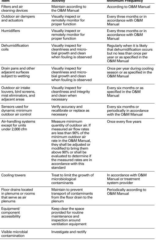
ASHRAE 62-2001 addresses the issue of inspecting and cleaning ventilation systems by listing specific inspection intervals in Section 8.4.1 (see Figure 5). Additionally, the standard requires that:
“Visible microbial contamination shall be investigated and rectified.”
(Section 8.4.2)
Historically, HVAC equipment and ductwork has been lined with porous, matte-faced fiberglass for thermal insulation and acoustical attenuation. The porous surface of the insulation can store dirt, creating a habitat for microbial growth if moisture is present. Once contaminated with mold, the porous insulation is almost impossible to clean short of removing and replacing it. Section 5.5 of the ASHRAE Standard 62-2001 includes specific requirements for the materials used on surfaces inside HVAC equipment and ductwork that are exposed to the airstream.
“Visible microbial
contamination shall be
investigated and rectified.”
(Section 8.4.2)
Total Trap Height (W) = X + H + 1.5 x D Where:
X = 1⁄2H
H = At Least 1" Plus Casing Static Pressure D = Pipe Diameter Total Trap Height (W) X H Housekeeping Pad
water. Central air handlers and large rooftop equipment typically require a more durable liner (such as sheet metal) because of their physical size and maintenance requirements. Today, Trane offers cleanable interior surfaces on its entire line of commercial air-handling products to simplify inspection and any cleanup that may be required.
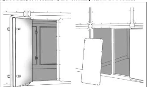
Accessibility
Obviously, a cleanable surface is of limited value if it cannot be accessed easily. ASHRAE Standard 62-2001 states:
“Provision shall be made for periodic in-situ cleaning of cooling coils and condensate pans. Air handling and fan-coil units shall be easily accessible for inspection and preventative maintenance.”
(Section 5.11)
This section of the standard clearly requires that cooling coils and drain pans must be readily accessible for inspection, cleaning, and maintenance in their normal operating position (in-situ). Additionally, Section 8.4.1 lists specific inspection intervals for filters, cooling coils, drain pans, humidifiers, and outdoor-air intake louvers. These maintenance requirements are outlined in Table 8-1 of the standard (see Figure 5). Large access doors or removable panels are necessary to meet this This has prompted many designers to
specify commercial HVAC equipment with double-wall construction (fiberglass insulation sandwiched between two layers of metal) or external insulation for “wet” areas of the equipment and the duct system. This includes areas surrounding and immediately downstream of cooling coils and near humidifiers. Though effective for cleanability, an unlined duct system, whether double-wall or externally insulated, can be more expensive and may lead to acoustical problems. Trane believes that the intent of the standard can be met by using cleanable surfaces in the sections of the air handlers and ductwork expected to become wet during normal system operation. This includes outdoor air intakes and mixing boxes, cooling-coil sections of air handlers, and sections housing and immediately downstream of humidifiers.
The specific way in which the system meets the cleanability requirement varies by system type. Terminal equipment (such as fan-coils, blower coils, unit ventilators, and water-source heat pumps) that has physical space constraints, typically uses either closed-cell foam or foil-faced insulation. Both liner materials provide a nonporous outer surface that is impermeable to
9
Figure 5: Minimum Maintenance Activity and Frequency (Table 8-1) from ASHRAE Standard 62-2001
“Provision shall be made for
periodic in-situ cleaning of
cooling coils and condensate
pans. Air handling and fan-coil
units shall be easily accessible
for inspection and preventative
maintenance.”
(Section 5.11)
“Make-up air inlets and exhaust
air outlets shall be located to
avoid contamination of the
make-up air.”
“Contaminants from sources
such as cooling towers, sanitary
vents, vehicular exhaust from
parking garages, loading docks,
and street traffic should be
avoided.”
(Section 5.4)
“Special care should be taken to
avoid entrainment of moisture
drift from cooling towers into
the make-up air and building
vents.”
(Section 5.11)
“If the outdoor air contaminant
levels exceed the values given in
6.1.1 (Table 1), the air should be
treated to control the offending
contaminants.”
(Section 6.1.2)
For more information on these “IAQ Equipment Basics,” contact your local Trane representative for a copy of “Practice the Basics of Microbial Growth Control” (literature order number TECH-R-168).
Outdoor Sources
Contaminants can also enter a building from outdoors through the outdoor air intake, or by infiltration through cracks and openings in the building envelope. Regarding the former, ASHRAE Standard 62-2001 states:
“Make-up air inlets and exhaust air outlets shall be located to avoid contamination of the make-up air.”
(Section 5.4)
This statement requires the building designer to situate equipment in a way that prevents make-up air contamination. In other words, the outdoor air intake must not reintroduce exhaust air into the building. In built-up (applied) systems, this requirement usually can be met through careful placement of outdoor air intakes relative to exhaust fans, flue vents, etc. However, packaged roof-mounted unitary equipment can be more challenging. In these systems, the designer must subjectively determine the likelihood of outdoor air contamination, then select and locate equipment accordingly. The standard identifies specific contaminants to be avoided:
“Contaminants from sources such as cooling towers, sanitary vents, vehicular exhaust from parking garages, loading docks, and street traffic should be avoided.”
(Section 5.4)
and…
“Special care should be taken to avoid entrainment of moisture drift from cooling towers into the make-up air and building vents.”
(Section 5.11)
Although this is only advisory language, it seems to be a corollary to the
requirement for locating the make-up air intakes previously discussed in Section 5.4, they simply name additional requirement. In addition, the equipment
must be positioned and installed within the building to assure adequate access to all major components without substantial unit disassembly. It is reasonable to conclude that equipment that is easy to access will be maintained and serviced more often. In commercial central-station air-handling equipment, access is typically provided with hinged doors or removable panels. This same logic applies to system ductwork. Ductwork access should be provided at areas where dirt is likely to accumulate—for example, at changes in velocity or direction—as well as immediately before and after any duct-mounted devices such as humidifiers, turning vanes, and fire dampers. Equipment designs for commercial terminal products, such as fan-coils, water-source heat pumps and unit ventilators, should also allow easy inspection and maintenance (such as filter replacement) with minimal disassembly of the equipment. Easy access is especially important for equipment located in the occupied space. Terminal unit systems typically consist of multiple units, making inspection and maintenance a time-consuming process. Although
fan-powered VAV terminals do not have cooling coils or drain pans, they do have filters which must be replaced regularly. Access to the filters, as well as to the terminal units themselves, is critical. Trane designs all of its applied air-handling products with accessibility in mind. The panel-and-post construction of the Modular Climate Changer™ air handler, for instance, offers the flexibility of hinged access doors for regularly accessed areas, and fully removable panels for areas accessed less often. Likewise, filters in UniTrane™ fan-coil units can be changed without removing the front panel for faster filter
maintenance and less disruption to the occupants. If further maintenance is required, the entire front panel of the unit, as well as the drain pans, can be removed. VariTrane™ fan-powered VAV terminals provide complete access also. The entire bottom panel of the unit is removable to permit inspection, cleaning, and maintenance of the unit. 11
contaminant sources. If viewed as corollaries, these statements require the designer to account for all possible contamination sources when locating the system outdoor air intake. Vehicle traffic patterns around the property, prevailing wind direction, and the location of cooling towers, garbage dumpsters, and other contaminant sources must be considered. Incidentally, the statement in Section 5.11 should be interpreted to include any piece of outdoor equipment with standing water as a potential external contaminant source. According to Standard 62, if outdoor contaminants cannot be eliminated or avoided, local air cleaning of the outdoor air and dilution ventilation must be employed. (See the “Filtration” section on pages 29 - 30.) Even outdoor air of acceptable quality can become contaminated if it is brought into the building through contaminated outdoor air intakes and ductwork. Missing or damaged screens on outdoor air intake openings can allow birds and rodents to enter these areas and soil them with nesting materials and feces. Section 8.4.1.6 requires inspection of outdoor air intakes at least once every
six months, and requires cleaning or repair if necessary.
Obviously, the number of possible paths through the building shell make it difficult to filter contaminants that enter the building via infiltration. Proper building pressure control can effectively reduce infiltration, and thus limit the intrusion of contaminants and moisture from outdoors. Internal building pressure should be controlled to equal or slightly positive relative to the outdoors during both occupied and unoccupied periods. Building pressurization is discussed in more detail later in this guide.
Proper Ventilation
Another very important element of achieving acceptable indoor air quality is proper ventilation. ASHRAE Standard 62-2001 offers two methods for determining the amount of outdoor air required to properly ventilate indoor occupied spaces for acceptable IAQ: the Ventilation Rate Procedure and the IAQ Procedure.Equation 6-1 of the standard is
used to calculate the minimum
outdoor airflow required at the
system level:
“Indoor air quality shall be
considered acceptable if the
required rates of acceptable
outdoor air in Table 2 are
provided for the occupied
space.”
(Section 6.1.3)
Figure 6: Excerpt from Table 2 of ASHRAE Standard 62-2001
Y = X / (1+ X - Z)
V
ot
= Y x V
st
WHERE:
X = Von/Vst = uncorrected
outdoor airflow fraction Y = Vot/Vst = corrected outdoor airflow fraction Z = largest F = critical-space ventilation fraction F = Vo/Vs = space ventilation fraction Von = ∑Vo= sum of space ventilation airflows Vot = Y x Vst= required system outdoor airflow Vo = space ventilation airflow
Vs = space primary airflow
Ventilation Rate Procedure
(Section 6.1)
The Ventilation Rate Procedure dictates both the quantity and quality of ventilation air necessary to assure adequate dilution of contaminants generated in the occupied space. Sometimes referred to as the “dilution solution,” it provides a prescriptive ventilation method for achieving acceptable indoor air quality. Specifically, it prescribes a three-step approach: • First, determine the quality of the outdoor air. The designer cannot simply assume that the quality of the outdoor air surrounding the building is acceptable for use as ventilation air. Table 1 of the standard cites the “EPA National Ambient-Air Quality Standards for Outdoor Air” for particulate and gaseous contaminants. Particulate or gaseous filtration is necessary if outdoor air exceeds the threshold levels referenced. • Second, if the outdoor air is
unacceptable, the standard advises that it be cleaned or filtered:
“If the outdoor air contaminant levels exceed the values given in 6.1.1 (Table 1), the air should be treated to control the offending contaminants.”
(Section 6.1.2)
In other words, a building designer faced with unacceptable outdoor air is encouraged to treat the outdoor air before it enters the building.
• Lastly, determine the amount of outdoor air required in each space. Standard 62 states:
“Indoor air quality shall be considered acceptable if the required rates of acceptable outdoor air in Table 2 are provided for the occupied space.”
(Section 6.1.3)
Using the Ventilation Rate Procedure, an occupied space is considered to have acceptable IAQ if it is ventilated at the airflow rate specified in Table 2 of the standard. Said another way, compliance with the Ventilation Rate Procedure requires that individual spaces be ventilated using the values in Table 2. An excerpt from this table is shown in
“Where more than one space is
served by a common supply
system, the ratio of outdoor air
to supply air required…may
differ from space to space. The
system outdoor air quantity
shall then be determined using
Equation 6-1.”
(Section 6.1.3.1)
“When spaces are unoccupied,
ventilation is not generally
required unless it is needed
to prevent accumulation of
contaminants injurious to
people, contents, or structure.”
(Section 6.1.3.1)
13
Figure 6. To use Table 2, you must first determine the expected usage of that space within the facility. The ventilation rates are expressed as a volume flow rate per person, or per square foot, for a wide variety of space uses (such as office spaces, classrooms, corridors, and auditoriums). Once you know the design occupancy or floor area, you can calculate the ventilation flow rate required for each space.
Multiple-Space Systems
When a common supply air system serves multiple spaces (Figure 7) the building designer must calculate the system minimum outdoor airflow rate (that is, the quantity of outdoor air required at the air handler) based on the space-level ventilation requirements (per Table 2). Specifically, the standard states:
“Where more than one space is served by a common supply system, the ratio of outdoor air to supply air required …may differ from space to space. The system outdoor air quantity shall then be determined using Equation 6-1.”
(Section 6.1.3.1)
This requirement applies to both constant-volume and variable-air-volume (VAV) systems. Many constant-volume air handlers and almost all VAV air handlers serve more than one space. When a common supply system serves more than one occupied space, each space is likely to require a different ratio of outdoor air to supply airflow (space ventilation fraction). Simply bringing in a quantity of outdoor air that equals the sum of the individual space ventilation requirements usually results in most of the spaces being underventilated much of the time.
The VAV Ventilation Challenge To properly ventilate a multiple-space, VAV system, the percentage of outdoor air in the supply air stream must change as the amount of supply airflow to the spaces changes. Equation 6-1 links the individual space ventilation requirements to the amount of outdoor air that must enter the air handler that serves the entire system. Some designers believe that Equation 6-1 is excessively complex, but it is really quite straightforward. It involves comparing several ratios to
Figure 7: Multiple-Space System
calculate the amount of outdoor air required at the system-level air handler. The challenge of VAV system design is to properly ventilate all spaces at all load conditions. Supply air in VAV systems is a mixture of ventilation air and
recirculated air that is carried to the space by a single duct. That means the proportion of outdoor air in this supply air mixture must change as the supply airflow changes to maintain proper ventilation levels in the spaces. Many designers erroneously use the sum of the outdoor air requirements of all the spaces (Vonin Equation 6-1) in the system as the system-level ventilation rate. This method, sometimes referred to as the “average ventilation method,” does not comply with ASHRAE Standard 62-2001 because it underventilates the spaces at most operating conditions.
For more information on the challenge of properly ventilating VAV systems, refer to the “The Threefold Challenge of Ventilating Single-Duct VAV Systems” Engineers Newsletter (Volume 27, Number 1).
One way to address this problem is to dynamically vary the amount of outdoor air being introduced at the air handler in response to actual system operating conditions. This approach is referred to as Ventilation Reset and is discussed in
detail later in the “Ventilation Control Strategies” section of this guide (Pages 17 - 21).
Occupied vs. Unoccupied Ventilation If the potential exists for contaminants to accumulate in a space when it is unoccupied, ventilation may be required even when the space is unoccupied. Standard 62 states:
“When spaces are unoccupied, ventilation is not generally required unless it is needed to prevent
accumulation of contaminants injurious to people, contents, or structure.”
(Section 6.1.3.1)
In this case, the term “contaminants” seems to include humidity, due to the reference to a contaminant which is “injurious to contents or structure,” as well as those listed in Tables 1, 3, B-1, B-2, B-3, and B-4 of the standard. The unoccupied ventilation rate is determined by the contaminant emission rate. Indoor humidity can be measured and controlled by mechanical systems, but many of the other contaminants listed cannot be easily or reliably monitored. This leaves the designer with limited options, the most basic of which is time-of-day scheduling of ventilation during unoccupied periods.
Ventilation Effectiveness
“Ventilation effectiveness” is defined as the fraction of the outdoor air delivered
“The ventilation effectiveness is
defined by the fraction of the
outdoor air delivered to the
space that reaches the occupied
zone…It is, however, not
uncommon to find some of the
ventilation air bypassing the
occupants (moving from supply
to exhaust without fully mixing
in the occupied zone)…Such
flow conditions should be
avoided.”
(Section 6.1.3.3) Vot OA RA VAV BoxesVAV Rooftop Unit or Air Handler
Space 1 Space 2 Space 3
“Where peak occupancies of less
than three hours duration occur,
the outdoor airflow rate may
be determined on the basis of
average occupancy for buildings
for the duration of operation of
the system, provided the average
occupancy used is not less than
one-half of the maximum.”
(Section 6.1.3.4)
“Ventilating systems for
spaces with intermittent or
variable occupancy may have
their outdoor air quantity
adjusted…to provide sufficient
dilution to maintain
contaminant concentrations
within acceptable levels at
all times.”
(Section 6.1.3.4)
“When contaminants are
generated in the space or
the conditioning system
independent of occupants
or their activities, supply
of outdoor air should lead
occupancy so that the acceptable
conditions will exist at the start
of occupancy.”
(Section 6.1.3.4)
Ventilation effectiveness can have a significant effect on the amount of outdoor air required for the system. It is important to understand that even a modest amount of short circuiting of the outdoor air to the return, say 10 percent, results in a 10 percent increase in the amount of outdoor air required to properly ventilate the system.
This requirement points to the need to specify high quality supply-air diffusers with good throw characteristics at all flow conditions. Trane’s line of linear slot diffusers provides superior room airflow mixing performance, even at low airflow, and with minimal “dumping.” Models are available for most popular ceiling types.
Intermittent Occupancy
For some variable-occupancy spaces, the standard allows a calculated minimum space ventilation rate based on average space occupancy rather than peak space occupancy. Specifically, Standard 62 states:
“Where peak occupancies of less than three hours duration occur, the outdoor air flow rate may be determined on the basis of average occupancy for buildings for the duration of operation of the system, provided the average occupancy used is not less than one-half of the maximum.”
(Section 6.1.3.4)
Suppose, for example, a conference room has an average occupancy of 75 percent and that it will be occupied at design levels for less than three hours in duration. Under these circumstances, the design space ventilation rate could be calculated using the average space population (75 percent) rather than peak population (100 percent). The per person ventilation rate remains the Table 2 values. Auditoriums, conference rooms, and training or meeting rooms often qualify as intermittently occupied spaces. Interpretation IC 62-1999-18 helps clarify this provision by stating:
The occupancy is to be averaged over the duration of operation of the system …The intermittent occupancy provision contained in 6.1.3.4 of the Standard also can be applied to multiple daily episodes of peak occupancy as long as each is for
to the space that actually reaches the occupants. The section of the standard dealing with ventilation effectiveness is more descriptive than prescriptive. It does not tell the designer what to do as much as it explains the concept. ASHRAE Standard 62-2001 allows the use of outdoor air delivered to the occupied space to both dilute the concentration of contaminants and to transport them out of the occupied space. The ventilation rates listed in Table 2 of the standard assume that the air in the occupied space is well-mixed, with relatively uniform contaminant concentration levels throughout the space. It states:
“The values in Table 2 define the outdoor air needed in the occupied zone for well-mixed conditions (ventilation effectiveness approaches 100 percent.”)
(Section 6.1.3.3)
The important point of this section is that the space ventilation rates listed in Table 2 assume “well-mixed” air within the space. In reality, however, the designer should not necessarily assume that all of the outdoor air entering the building gets to the occupied space, or more
importantly, to the occupants. The air that passes from the supply diffuser to the return grille without reaching the occupants should be discounted since it offers no dilution benefit. The standard states:
“The ventilation effectiveness is defined by the fraction of the outdoor air delivered to the space that reaches the occupied zone…It is, however, not uncommon to find some of the ventilation air to be bypassing the occupants (moving from supply to exhaust without fully mixing in the occupied zone)…Such flow conditions should be avoided.”
(Section 6.1.3.3)
The standard suggests that air distribution systems be designed to minimize bypass. The engineer must make a judgment on this value and increase the space ventilation rate by an appropriate amount to assure delivery of the proper amount of outdoor air, per Table 2, after accounting for ventilation effectiveness.
less than three hours. It is intended to apply to occupancy profiles that permit pollutant reduction through over-ventilation (on a per person basis) during intervening periods of reduced occupancy between peaks.
Standard 62 adds:
“Ventilating systems for spaces with intermittent or variable occupancy may have their outdoor air quantity adjusted …to provide sufficient dilution to maintain contaminant concentrations within acceptable levels at all times.”
(Section 6.1.3.4)
Although ASHRAE Standard 62-2001 allows the quantity of outdoor air being delivered to intermittently occupied spaces to be reduced below the values in Table 2, acceptable contaminant levels must also be maintained. Additionally, the intermittent occupancy provision cannot be used if the outdoor airflow is to be reduced during periods of partial occupancy (such as the case with CO2
-based demand-controlled ventilation). Interpretation IC 62-1999-4 states that:
If the total outdoor air supply based on the occupied space is reduced during periods of less occupancy by demand control, it is improper to also apply the variable provision of 6.1.3.4. Concentration of occupant generated contaminants would not then be adequately decreased with reduced occupancy to render the space suitable for future occupancy.
Preoccupancy Purge
The standard suggests that ventilation may need to precede occupancy for variable-occupancy spaces to assure that the indoor air is acceptable by the time occupancy begins. Specifically, the standard says:
“When contaminants are generated in the space or the conditioning system independent of occupants or their activities, supply of outdoor air should lead occupancy so that the acceptable conditions will exist at the start of
building materials and furnishings, and accumulate during unoccupied periods. The standard prescribes the required lead time based on occupant density and the required ventilation rate. This type of “lead-ventilation” control scheme is similar to night purge operation. Preoccupancy purge may be an effective way to assure that contaminants that may build up during unoccupied periods are removed prior to occupancy. However, it may still be necessary to manage indoor humidity levels during these intervals. As explained in the “Humidity Management” section of this guide, indoor humidity levels over 60 percent RH for periods as short as 24 hours can support the growth of some forms of mold and fungi.
Summary of Ventilation Rate Procedure Section 6.1 of ASHRAE Standard 62-2001 provides the building designer with a prescriptive method for achieving acceptable indoor air quality. It is very concise and complete for some design issues and somewhat unclear on others. Overall, it provides the engineer with a valuable, relatively well-defined procedure for designing and specifying ventilation systems.
For more information on the Ventilation Rate Procedure, refer to ASHRAE Standard 62-2001 and to the Trane Engineers Newsletter titled “ASHRAE 62-89 Analysis, Part 2: Ventilation Rate Procedure” (Volume 22, Number 1).
Indoor Air Quality Procedure
(Section 6.2)
The Indoor Air Quality (IAQ) Procedure presents an alternative, performance-based method for achieving acceptable indoor air quality by setting limits on the concentration of all known and
specifiable contaminants. More
specifically, the IAQ Procedure sets limits for 10 contaminants, prescribes a subjective analysis to determine
acceptable odor levels, and describes the
“Tables B-1 and B-3
do not include all known
contaminants that may
be of concern, and these
concentration limits may not,
ipso facto, ensure acceptable
indoor air quality with respect
to other contaminants.”
(Section 6.2.1)
“Recirculation with air-cleaning
systems is also an effective
means for controlling
contaminants when using the
Indoor Air Quality Procedure.”
concentration levels of 10 contaminants. By reference to these tables, the indoor concentration of the listed contaminants must be maintained below the levels listed. Even if levels are maintained below the maximum allowed, however, acceptable indoor air quality is not necessarily assured. The standard states:
“Tables B-1 and B-3 do not include all known contaminants that may be of concern, and these concentration limits may not, ipso facto, ensure acceptable indoor air quality with respect to other contaminants.”
(Section 6.2.1)
Odor control is another objective of this procedure. Many odor-causing contaminants cannot be measured in terms of concentration levels or do not have established concentration thresholds. Therefore, a designer cannot comply with the IAQ Procedure without a subjective evaluation of the completed system. The standard speaks to this subjective evaluation by stating:
“One method that may be used for measuring subjective response is described in Appendix B.”
(Section 6.2.2)
Appendix B outlines a method whereby if 80 percent of a panel of at least 20 untrained observers deems the air unobjectionable under representative use, the air quality is acceptable. These observations are intended to detect offensive odors only. The standard also cautions that meeting the requirements of the subjective test does not guarantee that other contaminants are not present. Cleaning of Recirculated Air
The IAQ Procedure allows cleaning (filtering) of recirculated air as a means to reduce the minimum space ventilation rates given in Table 2. It states:
“Recirculation with air-cleaning systems is also an effective means for controlling contaminants when using the Indoor Air Quality Procedure…If cleaned,
recirculated air is used to reduce the outdoor airflow rate below the values shown in Table 2, the Indoor Air Quality Procedure, 6.2, must be used.”
(Sections 6.2.3 and 6.1.3.2)
“If cleaned, recirculated air
is used to reduce the outdoor
airflow rate below the values
shown in Table 2, the Indoor
Air Quality Procedure, 6.2,
must be used.”
(Section 6.1.3.2)
To clean air returning from the occupied space, recirculate it as ventilating air, and thereby reduce the minimum outdoor airflow rates listed in Table 2, the designer must use the IAQ Procedure— not the Ventilation Rate Procedure. Some contaminants, particularly gaseous ones, may not be adequately cleaned from the recirculated air stream. Such contaminants can accumulate in the occupied space, eventually reaching unacceptable concentration levels. Therefore, acceptable indoor air quality must be determined using the performance-based IAQ Procedure. To avoid this necessity, many building designers do not specify cleaning recirculated air solely to reduce the minimum ventilation rate.
Summary of the IAQ Procedure
Section 6.2 of ASHRAE Standard 62-2001 attempts to provide the building
designer with an alternate method for providing acceptable indoor air quality through direct contaminant control. Unfortunately, the standard presents only a short list of acceptable contaminant levels. It also includes a requirement for a post-design, subjective evaluation for odors, and requires ongoing building system vigilance on the part of the designer after the building is designed and occupied. This leaves the building designer without a clear definition of acceptable indoor air quality. Consequently, most designers prefer the Ventilation Rate Procedure because its more prescriptive nature and clearer requirements provide a more straightforward path to compliance.
For more information on the Indoor Air Quality Procedure, refer to ASHRAE Standard 62-2001 and the Trane Engineers Newsletter titled “ASHRAE 62-89 Analysis, Part 3: Indoor Air Quality Procedure” (Volume 22, Number 2).
Ventilation Control Strategies
Typically, spaces within buildings are not occupied at the same levels at all times throughout the day. ASHRAE Standard 62-2001 requires that all spaces in a building must be properly ventilated at all system load conditions whenever the spaces are occupied. Specifically it states:
control the volume of outdoor air assures that the desired outdoor airflow is actually introduced into the system. It may also be beneficial as verification of the system’s actual performance. Ventilation Reset
This control strategy uses the actual airflow and design ventilation rate of each space in VAV systems to determine how much outdoor air is required at the system-level air handler. In a typical VAV system, the supply air is a mixture of outdoor air and recirculated return air that is delivered to the space through a common duct. While the amount of supply air to each space varies with thermal load, the amount of ventilation air required by that space often remains constant. Herein lies the challenge of properly ventilating buildings with VAV systems. To properly ventilate spaces served by VAV systems, the richness (or percentage) of outdoor air contained in the supply airstream must change as the volume of air delivered to the spaces changes. As noted earlier in our discussion of the Ventilation Rate Procedure, Equation 6-1 links the ventilation requirements of the individual spaces to the amount of outdoor air required at the system-level air handler.
“When the supply of air is reduced during times the space is occupied (e.g. in variable-air-volume systems), provision shall be made to maintain acceptable indoor air quality throughout the occupied zone.”
(Section 5.3)
As we discussed earlier in the “Multiple-Space Systems” section of this guide, systems serving more than one space must be capable of varying the ratio of outdoor air to supply air. This requirement has fostered a number of ventilation control strategies. All of them directly or indirectly attempt to track occupancy levels (count people) and/or loads within the spaces and reset the system outdoor airflow rate based on the need (or demand) for ventilation at that time.
Controlling a system operating parameter such as temperature or airflow by means other than directly measuring it can be difficult and many times inaccurate. In the case of outdoor airflow, the ability to measure and control the amount of outdoor air brought into the system is fundamental to properly ventilating multiple-space systems. The ability to measure and
“When the supply of air is
reduced during times the space
is occupied (e.g. in
variable-air-volume systems), provision
shall be made to maintain
acceptable indoor air quality
throughout the occupied zone.”
(Section 5.3)
Figure 8: Ventilation Reset System Control Strategy
Communicating BAS
Central Station Air Handlers with Controls
Outdoor Airflow Measurement and Control Device
Total Supply Airflow Required Ventilation Primary Airflow Calculated Space DDC/VAV Terminal RA OA SA
“Comfort (odor) criteria with
respect to human bioeffluents
are likely to be satisfied if the
ventilation results in indoor
CO
2concentrations less than
700 ppm above the outdoor air
concentration.”
(Section 6.1.3)
package called the Traq™ Comfort System. For complete details, see your local Trane representative for a copy of SYS-EB-2 and CLCH-S-26.
Scheduled Ventilation
The amount of ventilation air delivered to a space can also be varied based on a time-of-day schedule. This is especially appropriate for facilities with repeatable and documented occupancy patterns, such as schools. In this strategy, the ventilation schedule resides in the building automation system (BAS) which, in turn, communicates the outdoor airflow setpoint to the air handler or terminal unit serving the space. The outdoor airflow is reset as necessary (typically hourly in the case of schools) to match space occupancy schedules and associated ventilation requirements.
Resetting outdoor airflow based on a schedule of space occupancy can significantly reduce outdoor airflow during periods of low occupancy while complying with the standard’s requirement to properly ventilate at all times and at all operating conditions. The key again is the ability to measure and control system outdoor airflow. Trane has successfully implemented this control strategy on numerous school projects.
CO2-Based Demand-Controlled
Ventilation
Another method of controlling
ventilation is based on measured carbon dioxide (CO2) levels within the occupied
space. CO2, a byproduct of human
respiration, can serve as an indicator of space ventilation rate (outdoor airflow per person) or of the number of people occupying a space, and thus some use it to determine the amount of ventilation air required. ASHRAE Standard 62-2001 offers the following comment on CO2:
“Comfort (odor) criteria with respect to human bioeffluents are likely to be satisfied if the ventilation results in indoor CO2concentrations less than 700 ppm above the outdoor air concentration.”
(Section 6.1.3)
As the name implies, ventilation reset dynamically adjusts the amount of outdoor air brought into the building based on real-time system operating parameters to assure that each zone is properly ventilated at all times. Key hardware needed to implement a ventilation reset control system are: • direct digital controls (DDC) at the VAV
terminals and air handler,
• a building automation system (BAS) capable of calculating Equation 6-1, • and the ability to measure and control
the outdoor airflow at the air handler. Here is how ventilation reset works: The DDC/VAV terminals continually measure the amount of supply air delivered to each space. The design ventilation rate for each space is known by the DDC/VAV terminal controller or the BAS. Knowing the current supply airflow and the design ventilation rate, a ventilation fraction (F) can be continually calculated for each space. As the BAS polls the VAV terminals, it continually identifies the space with the critical (highest) space ventilation fraction. By summing the supply airflow from the VAV zones (Vst)
and knowing the ventilation fraction of the critical space (Z), the BAS system can solve Equation 6-1 to determine the exact amount of outdoor air that is needed at the air handler (Vot). The BAS
sends the new outdoor airflow setpoint to the air handler which repositions the outdoor-air damper to satisfy that specific operating condition. The result is a VAV system that fully complies with the ventilation requirements of ASHRAE Standard 62-2001 and minimizes costly overventilation.
Another important benefit that should not be overlooked is the ability of a “communicating” DDC control system to document system performance. The airflows for each zone can be easily logged by the BAS to provide verification of the ventilation provided to each zone in the event of legal challenges. The “data-rich” environment of a DDC control system can help prove that you are “doing it right.”
Trane combines the ventilation reset control strategy with a supply fan pressure optimization routine in a
Unlike the other excerpts we have examined, this statement is an
observation rather than a requirement or a suggestion. As such, it notes that odors associated with people are likely to be controlled if the space CO2concentration is maintained at a level less than 700 ppm above the outdoor concentration. This observation is often interpreted to mean that acceptable indoor air quality can be assured by maintaining the space CO2concentration at 700 ppm above the outdoor concentration. While this might be true in some cases, achieving acceptable indoor air quality is not always this easy. Many experts claim that the correlation between CO2and acceptable indoor air quality is weak. At concentrations typically found in buildings, CO2is not considered harmful. CO2is a “tracer gas” used to indicate the amount of people-generated contaminants (odors) in the space, but it does not reflect the indoor concentrations of other contaminants, such as those generated within the building (VOCs) or those brought in from outdoors.
The acceptability of using measured space CO2concentrations to control the amount of outdoor air introduced into
the system has been controversial. To date, ASHRAE has published four official interpretations dealing with this issue. In the first three interpretations, the ASHRAE committee concluded that just limiting the indoor CO2level to 700 ppm above the outdoor concentration, through either dilution or treatment, does notassure acceptable indoor air quality and does notmeet the requirements of Standard 62. The first interpretation (IC 62-1989-7) states that:
The Ventilation Rate Procedure is intended to control many more factors than the level of CO2. That very fact disallows the use of CO2control to reduce outdoor air intake below Table 2 values, if compliance with the
Ventilation Rate Procedure is claimed. The Indoor Air Quality Procedure requires consideration of many more factors than the level of CO2. Therefore, CO2control of outdoor air intake or the filtration of CO2cannot be used as sole proof of compliance under the Indoor Air Quality Procedure.
Filtration of CO2is not an appropriate way to comply with Standard 62, since CO2is a surrogate for other
For copies of these
interpretations, visit the
Standards section of the
ASHRAE Web site
(www.ashrae.org).
Figure 9: Equilibrium of CO2Concentration at Various Ventilation Rates
2000 1500 1000 10 cfm/person 15 cfm/person 20 cfm/person Indoor CO 2 Concentration (ppm) 700 ppm
The fourth and most recent
interpretation (IC 62-1999-33) allows the use of CO2-based demand-controlled
ventilation to reduce the outdoor air supply during periods of reduced occupancy, provided other system and control provisions are met. One such requirement is that the intermittent occupancy provision in Section 6.1.3.4 (see pages 15 - 16 of this guide) cannot be used to lower the maximum occupancy for the purpose of reducing the design ventilation rate.
A second provision suggests the need for a non-zero base ventilation rate
However, good practice, and the rationale on which the ventilation rates in Table 2 are based, indicates the need for a non-zero base ventilation rate to handle non-occupant sources whenever the space is occupied.
Neither this interpretation nor the standard currently defines this base ventilation rate. All the requirements listed in interpretation IC 62-1999-33 should be carefully studied before a CO2-based demand-controlled
ventilation control strategy is adopted. Using measured CO2levels to control
ventilation can reduce system operating costs, especially in applications where contaminant levels result primarily from people and where population varies significantly (such as gymnasiums, large meeting rooms, and auditoriums). Since occupancy of these types of spaces is generally planned and therefore known in advance, scheduling the ventilation requirements of these spaces may be simpler than meeting all of the provisions listed in interpretation IC 62-1999-33. Additionally, if the space qualifies for the intermittent occupancy provision of the standard, it may be easier to reduce the design population (and therefore the design ventilation rate), which also results in smaller equipment.
Outdoor Airflow
Measurement and Control
The ability to measure and control outdoor airflow at the air handler is fundamental to implementing any of the ventilation control strategies just discussed. One way to cost-effectively
contaminants. Removal of CO2may not have any effect on the contaminants for which it is a surrogate (e.g., occupant odors).
In the second interpretation (IC 62-1999-03), the committee clarified the 700 ppm value as follows:
The reference to 700 ppm CO2in Section 6.1.3 is only a point of information. This is not a requirement of ASHRAE 62-2001. Since it is not a requirement it is neither a ceiling value nor a time-weighted average value. Rather, it can be considered an indicator that the outdoor air ventilation may not meet the minimum requirements of the standard.
The third interpretation (IC 62-1999-04) further states:
The CO2level of 700 ppm above outdoors is a guideline based on the perception of human bioeffluents, not a ceiling value for air quality.
While CO2cannot be used to directly
determine whether there is acceptable IAQ in the space, it canbe used to determine the quantity of outdoor air (on a per person basis) that is being delivered to the space. By measuring the CO2concentration within a space
and the outdoor concentration, we can determine the real-time CO2differential
between indoors and outdoors.
The relationship between indoor/outdoor CO2differential and the quantity of
outdoor air (on a per person basis) being supplied to a space depends on the level of occupant activity and the associated CO2generation rate. An example of this
relationship is depicted in Figure 9. For example, when 15 cfm/person of outdoor air (with a CO2concentration
of 350 ppm) is delivered to a space, at equilibrium, the CO2concentration in
that space will be about 1050 ppm. This equates to a 700 ppm difference between indoor and outdoor CO2
concentrations.
This CO2differential can be used to reset
the ventilation system to deliver the proper amount of outdoor air per person (according to Table 2 in the standard), based on actual occupancy and air delivery operation. This practice is often called “CO2-based demand-controlled
ventilation”. 21
measure outdoor air in central station or large commercial rooftop air-handling units is to use airflow measurement dampers. An example of this technology is Trane’s Traq™ damper, which
combines airflow measurement and control in a single, factory-mounted device in lieu of standard blade dampers in the mixing box. The Traq damper directly measures airflow and can be used to measure outdoor air, return air, or both.
Trane Traq dampers perform the combined functions of a flow-measuring station and a set of control dampers, but with some important differences. Traditional airflow-measuring stations require additional lengths (up to three duct diameters) of straight ductwork entering and leaving the measurement device to obtain the cataloged accuracy. The unique flow-shaping bellmouth inlet of the Traq damper straightens and accelerates the airflow before it passes over the flow-sensing ring. Measurement accuracy is enhanced by temperature compensation and periodic automatic re-zeroing of the pressure transducer. From the standpoint of installation space, the bellmouth inlet design reduces the Traq damper’s entering ductwork requirement to merely a low velocity, 90-degree radius elbow directly ahead of the damper or one hydraulic duct diameter upstream for mitered elbows. Because it is an integral part of the air handler, there
Figure 10: Minimum Ventilation Rate with CO2-Based Demand-Controlled Ventilation
Vot
VPeople
Variable Ventilation Based on CO2Level
are no leaving ductwork restrictions. In effect, the Traq damper delivers the performance of an airflow measuring station in the space of a standard louvered outdoor air damper. Indirect methods of outdoor air measurement such as damper position, the use of the mixing equations (based on CO2or temperature), or fan speed usually do not provide the required accuracy at low airflow conditions to properly implement these ventilation control strategies. Therefore, direct measurement of outdoor airflow, with a device such as the Traq damper or an airflow measurement station, is recommended.
Traq airflow sensing and control technology is available today on Trane M-Series™ and T-Series™ Climate Changers, IntelliPak™ rooftop units, and commercial self-contained units. For technical application information on Traq damper systems, contact your local Trane representative and ask for CLCH-TS-8.
The new Operations and Maintenance section of Standard 62 (Section 8) addresses the calibration of outdoor airflow measurement devices as follows:
“Sensors whose primary function is dynamic minimum outdoor air control,
such as flow stations at an air handler and those used for demand control ventilation, shall have their accuracy verified…This activity shall occur at a minimum of once every six months.”
(Section 8.4.1.7)
Additionally, Section 8.4.1.8 requires that the minimum outdoor air quantity (in units designed to deliver less than 2,000 cfm of supply air) be measured at least every five years to verify the airflow rates are in compliance with the standard.
Building Pressure Control
An HVAC system should be controlled to maintain a neutral or slightly positive pressure inside the building relative to outdoors. A positive pressure prevents uncontrolled infiltration of outdoor air into the building through cracks and other small openings in the building shell. However, maintaining the correct pressure relationships at all operating conditions during occupied and unoccupied periods requires careful consideration in the design and operation of the system. Building pressure will be affected by natural stack and wind effects, as well as by mechanical effects such as bathroom, kitchen, and building exhaust fans, or the operation of an airside economizer.
Exhaust systems used in buildings with variable-air-volume (VAV) systems must be capable of modulating airflow in response to the varying system supply air. A constant volume exhaust system can create a negative pressure within the building as the system supply airflow throttles down at part-load conditions. Another important consideration is coordination of the exhaust and supply air systems during unoccupied periods. A similar negative pressure situation will occur if the exhaust system (including bathroom exhaust and other local exhaust fans) operates when the main supply air system is idle. Coordination of building exhaust and intake at all times is crucial to proper building pressurization. Many designers try to control building pressure by indirectly tracking system exhaust and outdoor air intake based on fan speed, or inlet vane or discharge damper position. Often, this approach does not yield the accuracy necessary for proper building pressure control. Variable resistances caused by filter loading, stack effect, and wind can considerably affect building pressure balance. For this reason, Trane
recommends controlling space pressure by directly measuring the pressure differential across the building envelope.
23
Figure 11: Trane Traq Damper
Traq Damper Mixing Box Flow-Shaping Bellmouth Inlet Averaging Flow Sensor Low Leak Dampers
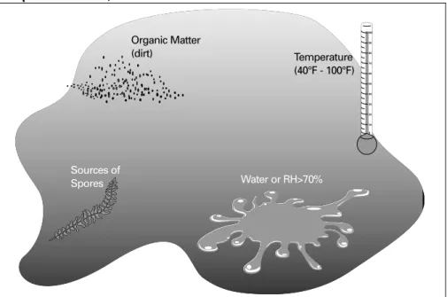
recommends maintaining indoor relative humidity levels between 30 percent and 60 percent. Humidity levels less than 30 percent cause some people respiratory discomfort while humidity levels over 70 percent near surfaces for extended periods of time promote the growth of some forms of mold and fungi. Today, microbiological contamination (mold and fungi) is a common cause of occupant complaints and IAQ problems in buildings. Although there are many different species of fungi, they all share the same basic needs for survival: • organic matter (nourishment) • moisture (liquid water or relative
humidity > 70 percent)
• moderate temperatures (40°F to 100°F) • source of spores
Controlling indoor moisture levels is one way to control propagation of fungi and dust mites inside buildings: in the carpets, wall coverings, and furnishings, as well as within the HVAC system itself. Direct building pressure control can be
accomplished at the unit level (stand-alone) with devices such as the Statitrac™ system on Trane IntelliPak rooftop units or through coordination of system components using a Trane Tracer Summit™ building automation system. Contact your Trane representative to discuss available building pressure control options.
For more information on building pressurization control, contact your local Trane representative for a copy of the “Building Pressurization Control” application manual (literature order number AM-CON 17).
Humidity Management
Uncontrolled moisture in buildings can contribute to unacceptable indoor air quality, occupant discomfort, and damage to the building structure and furnishings. One source of building moisture is water vapor contained in the indoor air. ASHRAE Standard 62-2001“High humidities can support
the growth of pathogenic or
allergenic organisms. Examples
include certain species of fungi,
associated mycotoxins, and dust
mites…Relative humidity in
habitable spaces preferably
should be maintained between
30 percent and 60 percent
relative humidity to minimize
growth of allergenic and
pathogenic organisms.”
(Section 5.10)
Figure 12: Traq Damper Installation with Radius Elbow
Radius Elbow R/H ≥0.75
For more detailed information on the problem of moisture in buildings, contact your local Trane representative for a copy of the “Managing Building Moisture” application manual (literature order number SYS-AM-15).
Most buildings require some form of humidity control: dehumidification, humidification, or both. HVAC systems differ in their ability to control humidity. Most air-conditioning systems