Test Procedures Manual
By Bob Allison, WB1GCM, ARRL Test Engineer
Michael Tracy, KC1SX, ARRL Technical Advisor
Mike Gruber, W1MG, ARRL EMC/RFI Engineer
Revision history:
Initial document: September 1990
Revision A, October 1992, updates and corrections
Revision B, January 1996, major revision, additional tests added Revision C, April 1997, updates and corrections
Revision D, November 1997, new graphics, updates and corrections Revision E, August 1998, expanded test information added
Revision F, June 2000, BER test box changes added
Revision G, January 2002, new schematics added to Appendix A Revision H, June 2004, updates for new test equipment added Revision I, January 2009, major revision, additional tests added Revision J, June 2009, updates and corrections
Revision K, January 2010, updates and corrections Revision L, May 2011, updates
TABLE OF CONTENTS
I. PURPOSE AND SCOPE 3
II. LIST OF FIGURES 4
III. LIST OF REQUIRED TEST INSTRUMENTS 5
IV. TRANSMITTER TESTS 6
4.1 OUTPUT POWER TEST 7
4.2 TRANSMIT FREQUENCY RANGE TEST 9
4.3 CW TRANSMIT-FREQUENCY ACCURACY TEST 11
4.4 SPECTRAL PURITY TEST 13
4.5 TWO-TONE TRANSMIT IMD TEST 16
4.6 SSB CARRIER AND UNWANTED SIDEBAND SUPPRESSION AT 14.250 MHz 18
4.7 CW KEYING WAVEFORM TEST 21
4.8 PTT TO SSB/FM RF OUTPUT TEST 23
4.9 TRANSMIT/RECEIVE TURN-AROUND TEST 27
4.10 KEYER SPEED AND SIDETONE FREQUENCY TEST 30
4.11 COMPOSITE NOISE TEST 32
V. RECEIVER TESTS 35
5.1 NOISE FLOOR TEST 36
5.2 AM RECEIVE SENSITIVITY TEST 39
5.3 FM SINAD AND QUIETING TEST 41
5.4 RECEIVE FREQUENCY RANGE TEST 44
5.5 FIRST IF AND IMAGE REJECTION TEST 46
5.6 ANTENNA PORT ISOLATION TEST 49
5.7 BLOCKING GAIN COMPRESSION 51
5.7A RECIPROCAL MIXING 54
5.8 TWO-TONE 2ND AND 3RD ORDER DYNAMIC RANGE TEST 57
5.9 FM ADJACENT-CHANNEL SELECTIVITY TEST 61
5.10 FM TWO-TONE 3RD ORDER DYNAMIC RANGE TEST 64
5.11 AUDIO POWER OUTPUT TEST 68
5.12 AUDIO AND IF FREQUENCY RESPONSE TEST 70
5.13 SQUELCH SENSITIVITY TEST 73
5.14 S METER TEST 75
5.15 IN BAND IMD TEST 77
5.16 NOTCH FILTER TEST 80
5.17 DSP NOISE REDUCTION TEST 86
5.18 EQUIVALENT RECTANGULAR BANDWIDTH TEST 89
5.19 NOISE FIGURE CALCULATION 89
VI. NON-STANDARD AND SPECIAL PURPOSE TESTS 90
6.1 LOW VOLTAGE AND TEMPERATURE CHAMBER TEST 90
6.3 RECEIVER BIT-ERROR RATE TEST 93
6.4 TRANSMITTER BIT-ERROR RATE TEST 95
6.6 POWER METER TEST 98
DATA SHEETS 103
6.7 HF LINEAR AMPLIFIER TEST 129
6.7B LINEAR AMPLIFIER IMD TEST 131
LINEAR AMPLIFIER DATA SHEET 135
ABOUT THE LINEAR AMPLIFIER IMD TEST FIXTURE 136
VII. APPENDIX A: ARRL CUSTOM TEST CIRCUITS 137
PURPOSE AND SCOPE
1.1 PURPOSE
The purpose of this manual is to ensure that all ARRL testing of HF transceivers, transmitters, and receivers will be conducted in a consistent and well-defined manner. The procedures used for this testing have been broken down into clear, step-by-step
instructions. All testing should be "done by the book" in order to guarantee that all equipment is evaluated to the same standards. This manual contains three major sections: Transmitter tests (Chapter 4), Receiver tests (Chapter 5) and Data Sheets (Chapter 6). The data sheets are arranged to allow test results to be recorded in the same order that measurements are taken.
1.2 SCOPE
This manual is designed to cover a wide range of amateur HF equipment. It is not intended to replace common sense or the expertise of an experienced test engineer. It is important, therefore, for the test engineer to be familiar with the Lab test equipment and the Device Under Test (DUT). The manufacturer's manual for the DUT should be completely read and understood before any testing is performed. At no time should any equipment be operated in a manner that is inconsistent with the manufacturer's recommended procedures or published limits. Failure to understand the unit under test could result in test error or, even worse, damage to the equipment, or worst of all, damage to the test engineer.
II. LIST OF FIGURES
Figure Description
4-1 Power Output Test Hook-Up
4-2 Transmit Frequency Range Test Hook-Up (no changes from 4-1) 4-3 CW Transmit Accuracy Test Hook-Up
4-4 Spectral Purity Test Hook-Up 4-4A Example Spectral Purity Plot
4-5 Two-Tone Transmit IMD Test Hook-Up
4-6 SSB Carrier and Unwanted Sideband Suppression Test Hook-Up (no changes from 4-5) 4-7 CW Keying Waveform Test Hook-Up
4-7A Example Scope Trace of RF Output CW Keying Waveform 4-8 PTT SSB/FM RF Output Test Hook-Up
4-9 Transmit/Receive Turn-Around Time Test Hook-Up 4-10 Keyer Speed and Side-tone Frequency Test Hook-Up 4-11 Composite Noise Test Hook-Up
5-1 CW Minimum Discernible Signal (MDS) Test Hook-Up 5-2 AM Receive Sensitivity Test Hook-Up
5-3 FM SINAD and Quieting Test Hook-Up 5-4 Receive Frequency Range Test Hook-Up 5-5 First IF and Image Rejection Test Hook-Up 5-6 Antenna Port Isolation Test Hook-Up 5-7 Blocking Gain Compression Test Hook-Up 5-7A Reciprocal Mixing Test Hook-Up
5-8 Two-Tone, 3rd Order Dynamic Range Test Hook-Up 5-9 FM Adjacent Channel Selectivity Test Hook-Up
5-10 FM Two-Tone, 3rd Order Dynamic Range Test Hook-Up 5-11 Audio Power Output Test Hook-Up
5-12 Audio and IF Frequency Response Test Hook-Up 5-13 Squelch Sensitivity Test Hook-Up
5-14 S-Meter Test Hook-Up 5-15 In-Band IMD Test Hook-Up 5-16 Notch Filter Test Hook-Up
5-17 Equivalent Rectangular Bandwidth Test Hook-Up 6-1 Low Voltage and Temperature Chamber Test Hook-Up 6-2 DSP Noise Reduction Test Hook-Up
6-3 Receiver Bit-Error-Rate (BER) Test Hook-Up 6-4 Transmitter Bit-Error-Rate (BER) Test Hook-Up 6-5 Receiver Phase-Noise Test Hook-Up
I I . LI ST OF REQUI RED TEST I NSTRUM ENTS
Instrument (or equivalent) Manufacturer Model Qty. Spectrum Analyzer HP HP8563E 1 Distortion/Audio Meter HP 339A 1 RF Signal Generator IFR 2041 1 RF Signal Generator Marconi 2041 1 In-line RF Wattmeter BIRD 4381 1 RF Signal Generator Rhode&Schwarz CMT 54 1 Digital Phosphor Oscilloscope Tektronix 3052B 1 Two-Tone Audio Generator ARRL N/A 1 Power Attenuator BIRD 8329 1 Keying-Test Generator ARRL N/A 1 Adjustable RF Attenuators HP 355C/D 1 Hybrid Combiner Ten-Tec 651 (2-60 MHz) 1
Voltmeter Bench N/A 1
Ammeter Bench N/A 1
Phase-Noise Mixer ARRL N/A 1 14.025 MHz Low-Noise Osc. ARRL N/A 1
Power Supply HP 6268B 1
Telegraph Key Any N/A 1
Attenuators BIRD 8340-100 or similar As R'qd HI-Z Audio Monitor Amp ARRL N/A 1 Wideband Noise Generator Elecraft N-gen 1
I V. TRANSM I TTER TESTS
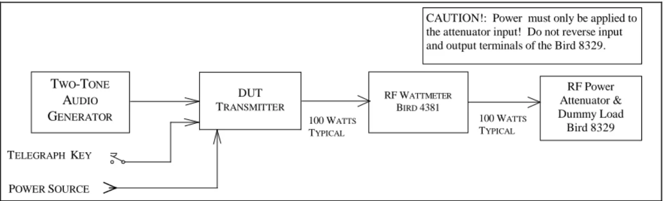
4.0.1 As shown in the Table of Contents, there are 11 transmitter tests outlined in this chapter. They have been arranged to minimize the required number of hook-up changes and modifications. However, each hook-up is shown complete, with all changes from the previous test clearly indicated. A block diagram accompanies each hook-up and any changes from the previous test are shown within a dotted rectangle. This affords the flexibility to easily start anywhere within the test plan and to perform these tests in any desired order.
4.0.2 Before any transmitter testing is performed, it is essential for the test engineer to be completely familiar with the Device Under Test (DUT) and the test equipment that will be used. The transmitter output power must not exceed the limitations of any test equipment used or the manufacturer's specifications for the DUT – including duty cycle or time. The transmitter must be operated in a manner exactly as specified and be properly tuned. Any test in this manual that would cause a piece of equipment to be operated in a manner inconsistent with its manual must be accordingly modified as required by the test engineer.
4.0.2.1 Other considerations are as follows: Spectrum Analyzer/Frequency Counter
The input to the spectrum analyzer or frequency counter should not exceed the range of –5 dBm to 0 dBm. Therefore, it is necessary to attenuate the output of transmitters or amplifiers down to this level. For example, if a particular transmitter is rated at 100 watts output, it will be necessary to use 50 dB of attenuation to obtain a level of 0 dBm.
RF Power Meter
The necessary element for the inline RF-power meter must be selected for the expected power and frequency. There are also multiplier switches on the wattmeter. Select the combination of switches that equals the power rating of the element.
RF Power and Step Attenuators
RF power attenuators have an INPUT and an OUTPUT. Make sure that the RF source is connected to the INPUT of the power attenuator. Connecting RF power to the OUTPUT of the attenuator will result in damage to the attenuator or to the transceiver. The attenuators have a power rating, which must be observed. It is always best to be conservative.
4.1 OUTPUT POWER TEST
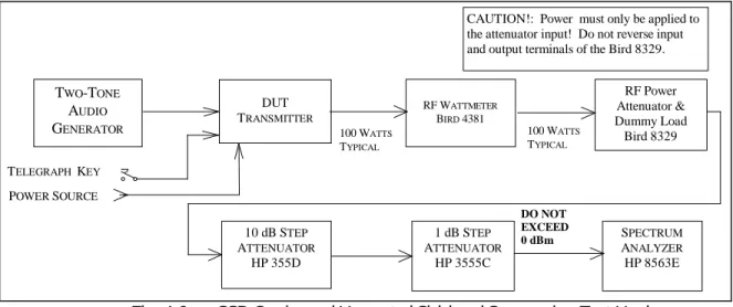
4.1.1 The purpose of the Transmitter Output Power Test is to measure the RF output power of the DUT across each band in each of its available modes. A two-tone audio input, at a level within the manufacturer's microphone-input specifications, will be used for the SSB mode. No modulation will be used in the AM and FM modes. DC current consumption at the manufacturer's specified supply voltage is also measured, if applicable.
4.1.2 Test hook-up (See Fig. 4-1)
4.1.2.1 With all test equipment and DUT power switches in the OFF position and the transceiver in the receive mode, connect the following:
Connection Connectors Cable Type
DUT RF OUTPUT to Wattmeter INPUT As Required to Type N 50-Ohm Coax Wattmeter OUTPUT to RF Power Attenuator Type N to Type N 50-Ohm Coax Two-Tone Audio Generator to Banana or BNC Coax
DUT Microphone INPUT to As Required
Telegraph Key to DUT KEY INPUT As Required As Required
AC power Only/AC Source to As Supplied with DUT As Supplied with DUT DUT Power Input
DC Power Only As Required As Required
1) Power supply to AC source.
2) Power supply OUT to voltmeter and ammeter.
3) Set power supply to specified voltage and connect to DUT.
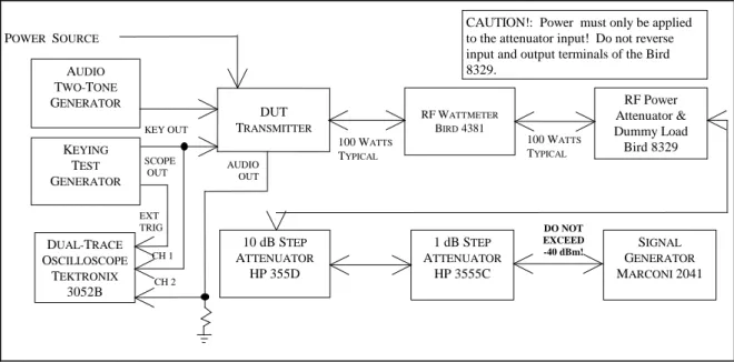
CAUTION!: Power must only be applied to the attenuator input! Do not reverse input and output terminals of the Bird 8329.
RF Power Attenuator & Dummy Load Bird 8329 100 WATTS TYPICAL 100 WATTS TYPICAL RF WATTMETER BIRD 4381 TWO-TONE AUDIO GENERATOR DC ONLY AC ONLY PTT SWITCH TELEGRAPH KEY DUT TRANSMITTER POWER SUPPLY
4.1.3 Test Procedure
4.1.3.1 Turn the DUT and RF wattmeter power switches to ON and set the following controls:
Instrument Control Position
Two-Tone Audio Generator TONE A OFF
TONE B OFF
HI-Z/LO-Z As Required
BALANCE Center
LEVEL Full CCW
Attenuator –30 dB
RF Wattmeter Mode Select Button FWD PEP
Element As Required Forward Element Range As Required
DUT Mode CW
BAND Selector Lowest Available
XMIT/RCV Receive
DRIVE or RF LEVEL Minimum 4.1.3.2 Allow all equipment at least 10 minutes warm-up time before proceeding to step 4.1.3.3
4.1.3.3 Tune the DUT per the operator’s manual. Put the DUT in the CW transmit mode at minimum DRIVE/RF LEVEL.
NOTE: The following three paragraphs, 4.1.3.4 , 4.1.3.5 and 4.1.3.6 apply only to transceivers with a DC power supply. Skip these paragraphs if testing an ac-powered DUT and make a note of the power type on Data Sheet.
4.1.3.4 Depress telegraph key. Observe that some minimum level of RF power is shown by the DUT Power Output Meter and Bird Wattmeter. Increase the RF DRIVE/LEVEL control if necessary. Record the power-supply ammeter and voltmeter values in 4.1.3.4 of the data sheet.
4.1.3.5 Increase RF DRIVE/LEVEL control to the maximum allowed by the manufacturer. Again, depress the telegraph key and record the power-supply meter readings in 4.1.3.5 of the data sheet. Decrease the RF DRIVE control to minimum. Release the telegraph key.
4.1.3.6 Increase the DUT AF gain control to maximum. (There should be no input signal.) Any light or display illumination should be in the default position. Measure and record the power supply readings as in the previous step. 4.1.3.7 Depress the key and observe the DUT power output meter and wattmeter indications. Slowly tune the DUT to the upper band edge while observing these meters. Release the key and record the maximum value observed on the wattmeter in 4.1.3.7 of the data sheet.
4.1.3.8 Increase the DRIVE/RF LEVEL control to the maximum allowed. Depress the telegraph key. Slowly tune the DUT down to the lower band edge while observing both the DUT power output meter and wattmeter as in the previous step. Release the telegraph key and record the minimum wattmeter values observed in 4.1.3.8 of the data sheet. Return the DRIVE/RF LEVEL control to minimum.
4.1.3.9 Set the DUT for the lower edge of the 80-meter band and retune as necessary. Repeat steps 4.1.3.7 and 4.1.3.8. Record all values in 4.1.3.9 of the data sheet. Repeat this procedure for all the remaining bands. Record both
the DUT power output meter and wattmeter indications for the 20-meter band. Note any significant deviations in the DUT meter indication observed between bands.
4.1.3.10 Return the transmitter to the lower edge of the 20-meter band and retune as necessary. Set the two-tone audio generator power switch to ON. Adjust for proper balance between both tones by setting the BALANCE control to the position so indicated. Adjust the generator LEVEL control for maximum specified ALC. Set the RF wattmeter to FWD PEP. Place the DUT in the USB mode and tune as required with the DUT mic gain control set about
half-way. Adjust the audio generator for maximum audio as specified by the manufacturer's manual with the DUT mic gain control set about half-way.
4.1.3.11 Repeat steps 4.1.3.7 and 4.1.3.8 and using the PTT switch to key the transmitter. Verify similar power output performance with the DUT in the LSB mode. Note any significant deviation from the USB mode. Record DUT power output meter and wattmeter indications in 4.1.3.11 of the Data Sheets.
4.1.3.12 Set the RF Wattmeter to FWD CW and the two-tone generator power switch to OFF. Return the transmitter to the lower edge of the 80-meter band. Place the DUT in the AM mode. Repeat steps 4.1.3.7 and 4.1.3.8 using the PTT switch to key the transmitter. Be sure not to exceed the maximum power output specified by the manufacturer for this mode. Record DUT power output meter and wattmeter indications in 4.1.3.12 of the Data Sheets.
4.1.3.13 Return the transmitter to the lower edge of the 10-meter band. Place the DUT in the FM mode. Repeat steps 4.1.3.7 and 4.1.3.8 for this mode. Be sure not to exceed the maximum power output specified by the manufacturer for this mode.
NOTE: Proceed to the following step only if the DUT has a transverter output.
4.1.3.14 Put the DUT into the CW mode and activate the transverter function.. Set to the 15 meter band. Connect the HP-437 microwatt meter and any needed attenuation to the transverter output. (Input to the microwatt meter must not exceed +20 dBm.) Repeat steps 4.1.3.7 and 4.1.3.8. Record on Data Sheet. Also observe and record any RF output that may appear at the normal antenna output.
4.2 TRANSM I T FREQUENCY RANGE TEST
4.2.1 The purpose of the Transmit Frequency Range Test is to determine the range of frequencies, including those outside amateur bands, for which the transmitter may be used.
4.2.2 Test Hook-up (See Fig. 4-2)
NOTE: No further hook-up changes are required if proceeding directly from the previous Power Output Test. This hook-up procedure, therefore, does not apply in this case and you may now proceed to step 4.2.3.1. 4.2.2.1 Connect the following with all power switches in the OFF position and the transceiver in the receive mode:
Connection Connectors Cable Type
DUT RF OUTPUT to Wattmeter INPUT As Required to Type N 50-Ohm Coax Wattmeter OUTPUT to RF Power Attenuator Type N to Type N 50-Ohm Coax Telegraph Key to DUT KEY INPUT As Required As Required
DC Power Only As Required As Required 1) Power supply to AC source.
2) Power supply OUT to voltmeter and ammeter.
3) Set power supply to specified voltage and connect to DUT.
4.2.3 Test Procedure
4.2.3.1 Turn the DUT and RF wattmeter power switches to ON and set the following controls:
Instrument Control Position
RF Wattmeter Mode select button FWD CW
Element As Required
Power Range As Required
DUT Mode CW
Band Selector Lowest available band
XMIT/RCV RECEIVE
DRIVE/RF OUT Minimum
4.2.3.2 Allow all equipment at least 10 minutes warm up time.
4.2.3.3 Tune the DUT per the operator’s manual for the lowest available band. Return the DRIVE/RF OUTPUT control to minimum. (The DUT should still be in the CW mode.)
4.2.3.4 Tune down near the low end of the band. Depress the telegraph key. Observe some minimum RF indication on the wattmeter. Slowly tune down until the RF drops out or the manufacturer's specified limit is achieved. Release the key and record this frequency, as indicated by the DUT display in 4.1.3.4 of the data sheet.
4.2.3.5 Tune to the upper limit of the band. Again, depress the telegraph key and slowly tune up until the RF drops out. Release the key and record this frequency in 4.1.3.5 of the data sheet.
4.2.3.6 Repeat steps 4.1.3.3 to 4.1.3.5 for all remaining available bands on the DUT.
CAUTION!: Power must only be applied to the attenuator input! Do not reverse input and output terminals of the Bird 8329.
RF Power Attenuator & Dummy Load Bird 8329 100 WATTS TYPICAL 100 WATTS TYPICAL RF WATTMETER BIRD 4381 TWO-TONE AUDIO GENERATOR TELEGRAPH KEY DUT TRANSMITTER POWER SOURCE
4.3 CW TRANSM I T-FREQUENCY ACCURACY TEST
4.3.1 The purpose of the CW Transmit-Frequency Accuracy Test is to measure and compare the actual output frequency of the DUT with its display adjusted for 14.000 MHz down to the least significant available digit. 4.3.2 TEST HOOK-UP (See Fig. 4-3)
NOTE: If proceeding directly from the previous Transmit Frequency Range Test, you need only modify the existing hook-up. Proceed to the steps indicated with a dotted line.
4.3.2.1 With all power switches in the OFF position and the transceiver in the receive mode, connect the following:
Connection Connectors Cable Type
DUT RF OUTPUT to wattmeter INPUT As Required to type N 50-Ohm coax Wattmeter OUTPUT to Power Attn INPUT Type N to type N 50-Ohm coax --- Pwr Attn OUT to 10-dB step INPUT Type N to BNC 50-Ohm coax 10-dB step Attn OUT to 1-dB step IN BNC to BNC 50-Ohm coax 1-dB step ATTN OUT to Freq Counter IN BNC to BNC 50-Ohm coax --- Telegraph key to DUT KEY INPUT As Required As Required
AC or DC power to DUT As Required As Required
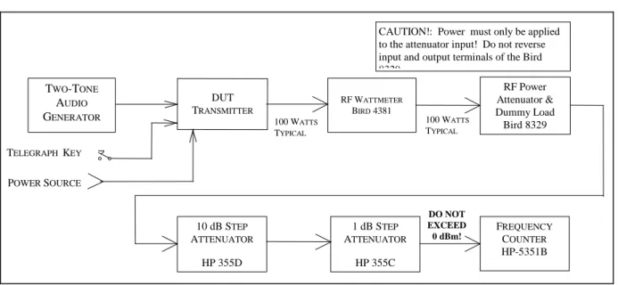
CAUTION!: Power must only be applied to the attenuator input! Do not reverse input and output terminals of the Bird 8329 RF Power Attenuator & Dummy Load Bird 8329 100 WATTS TYPICAL 100 WATTS TYPICAL RF WATTMETER BIRD 4381 TWO-TONE AUDIO GENERATOR TELEGRAPH KEY DUT TRANSMITTER POWER SOURCE 10 dB STEP ATTENUATOR HP 355D 1 dB STEP ATTENUATOR HP 355C FREQUENCY COUNTER HP-5351B DO NOT EXCEED 0 dBm!
4.3.3 Test Procedure
4.3.3.1 Turn the DUT, RF wattmeter and frequency counter power switches to ON. Set the following controls:
Instrument Control Position
DUT Mode CW
Band Selector 20 Meters Frequency 14.000 00 MHz
XMIT/RCV RECEIVE
DRIVE/RF OUT Minimum
RF Wattmeter Mode Select Button FWD CW
Element As Required Power Range As Required
10-dB Step Attn Attenuator 40 dB
1-dB Step Attn Attenuator Any
Frequency Counter 50 Ohm 50 Ohm (Depress)
4.3.3.2 Key the transmitter. Observe the minimum output power on the RF wattmeter and unkey the transmitter. Set the step attenuators to provide –5 to 0 dBm input to the frequency counter.
Do not exceed the maximum input limitation to the Frequency Counter.
4.3.3.3 Check and readjust, if necessary, the DUT for 14.000 00 MHz as indicated by its display. Record this value if the DUT has a digital type display, or, as best as possible with an analog display.
4.3.3.4 Key the transmitter and note the frequency as indicated by both the DUT and the frequency counter. Place a check mark in 4.3.3.4 of the data sheet if there is any significant deviation from 14.000 00 MHz
4.3.3.5 Increase the step attenuators to 40 dB. Set the transmitter power to the maximum allowed. Key the
transmitter and observe the RF output power as shown by the wattmeter. Set the attenuators to provide –5 to 0 dBm input to the counter.
4.3.3.6 Key the transmitter. Record the DUT and Frequency Counter indications in 4.3.3.6 of the Data Sheet. Unkey the transmitter.
4.3.3.7 Reduce the voltage to 12 V dc (if using a DC supply). Again key the transmitter and note the frequency displayed on the DUT and frequency counter. Place a check mark in 4.3.3.7 of the data sheet if there is any significant deviation from initial data.
4.4 SPECTRAL PURI TY TEST
4.4.1 The purpose of the Spectral Purity Test is to determine and measure the content of any spurious emissions in the output of the transmitter. Full-power carriers will be examined and minimum power checked on all available bands. 4.4.2 Test hook-up (See Fig. 4-4)
NOTE: If proceeding from the previous Transmit Frequency Accuracy Test, skip to the steps indicated with a dotted line.
4.4.2.1 With all power switches in the OFF position and the transceiver in the receive mode, connect the following:
Connection Connectors Cable Type
DUT RF OUTPUT to wattmeter INPUT As Required to type N 50-Ohm coax Wattmeter OUTPUT to Power Attn INPUT Type N to type N 50-Ohm coax Power Attn OUT to 10-dB step INPUT Type N to BNC 50-Ohm coax 10-dB step Attn OUT to 1-dB step IN BNC to BNC 50-Ohm coax --- 1-dB step Attn OUT to Spec Analyzer IN BNC to BNC 50-Ohm coax --- Telegraph key to DUT KEY INPUT As Required As Required
AC or DC power to DUT As Required As Required
CAUTION!: Power must only be applied to the attenuator input! Do not reverse input and output terminals of the Bird 8329.
RF Power Attenuator & Dummy Load Bird 8329 100 WATTS TYPICAL 100 WATTS TYPICAL RF WATTMETER BIRD 4381 TWO-TONE AUDIO GENERATOR TELEGRAPH KEY DUT TRANSMITTER POWER SOURCE 10 dB STEP ATTENUATOR HP 355D 1 dB STEP ATTENUATOR HP 3555C SPECTRUM ANALYZER HP 8563E DO NOT EXCEED 0 dBm
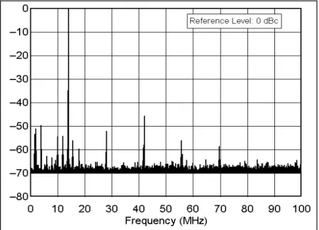
Fig. 4-4A ── Example Spectral Purity Plot 4.4.3 Test Procedure
4.4.3.1 Turn the DUT, RF wattmeter and spectrum analyzer power switches to ON and set the following controls:
Instrument Control Position
DUT Mode CW
Band Selector Lowest available
XMIT/RCV Receive
DRIVE/RF LEVEL Minimum
RF Wattmeter Push Button Mode Select FWD CW
Element As Required
Forward Element Range As Required
10-dB Step Attn Attenuator 40 dB
1-dB Step Attn Attenuator Any
Spectrum Analyzer START FREQ - STOP FREQ 0 – 50 MHz REF LEV (AMPLITUDE) –10 dBm ATTEN (AMPLITUDE) 20 dB
RES BW (BW) 10 kHz
VIDEO BW (BW) 30 kHz THRESHOLD (DISPLAY) –80 dBm SWP TIME (SWEEP) AUTO
4.4.3.2 NOTE: If proceeding directly from the previous CW Transmit Frequency Accuracy Test, skip this paragraph. Receiver hiss should be heard; adjust volume to desired level. Allow all equipment at least 10 minutes warm-up time before proceeding to step 4.4.3.3.
4.4.3.3 Tune the DUT per the operator's manual at the low end of the band. Put the DUT in the CW transmit mode at maximum DRIVE/RF LEVEL.
4.4.3.4 Depress the telegraph key and observe the power output shown by the Bird wattmeter. Release the key and set the step attenuators for –10 dBm input to the spectrum analyzer. CAUTION: The input to the spectrum analyzer at no time should exceed +10 dBm. Damage to this instrument will occur at an input level of +30 dBm or greater.1
4.4.3.5 Key the transmitter. The largest pip to the right of 0 MHz should be the fundamental. (This may be verified by use of the PEAK SEARCH button. With the marker to be at the top of the pip, the indicated marker frequency should be very close to the transmitted frequency.)
4.4.3.6 Adjust the REF LEV control on the spectrum analyzer so that the peak of the fundamental pip is at the Log Ref (0 dB) line on top of the display graticule. (To optimize the display, the FREQ START-FREQ STOP may be set for 0-10 MHz and the RES BW may be set for 30 kHz on the 160-meter band.)
4.4.3.7 The spectrum analyzer is now calibrated. The smaller pips are harmonics or spurs. The level of each spur, in dB below the fundamental, can be read directly from the display graticule. Each horizontal division represents 5 MHz each in the case of a 0-50 MHz frequency range. The frequency range may be adjusted for the specific display being considered, or as deemed appropriate by the test engineer. Each vertical division represents 10 dB.
4.4.3.8 Turn on the crystal calibrator, if the DUT has one, and observe any spurious emissions created by the calibrator. Record in notes section of data sheet and turn off the calibrator.
4.4.3.9 Slowly tune up the band while observing the analyzer display. Retune as necessary if the transmitter is not a broadband type. Note the worst case observed. Record on data sheet.
4.4.3.10 Reduce the transmitter power output to minimum. Again, observe the analyzer display while tuning down to the lower band edge. Note the worst case observed and record on data sheet.
4.4.3.11 Repeat steps 4.4.3.9 and 4.4.3.11 for all remaining available bands on the DUT. The Frequency Range settings for each band are as follows:
1.8 MHz 0-50 MHz 14 MHz 0-100 MHz 28 MHz 0-200 MHz 50 MHz 0-500 MHz 144 MHz 0-1000 MHz 222 MHz 0-1000 MHz 432 MHz: 0-2000 MHz
4.4.3.12 Return the transmitter to the worst case on the worst band. With the all significant spurs visible on the screen, take a single sweep by depressing the SGL SWP button. (Typically, this will be the second or third harmonic, although it is possible for VHF parasitic to be present.) The START FREQ, STOP FREQ and RES BW may be varied as required. Record all information on data sheet and save the plot to an appropriately named file.
1
4.5 TWO-TONE TRANSM I T I M D TEST
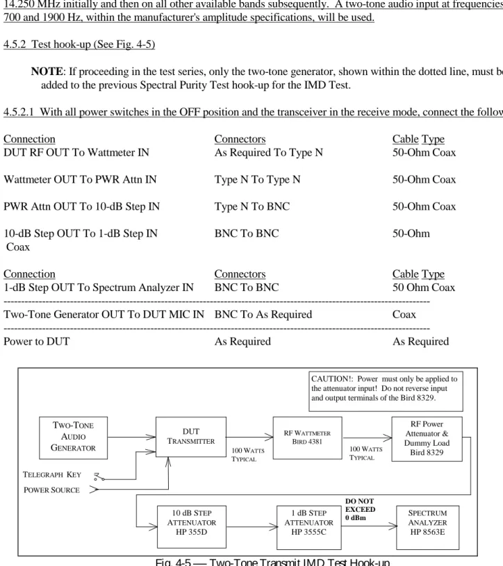
4.5.1 The purpose of the Two-Tone Transmit Test is to measure the intermodulation-distortion (IMD) products present in the RF output of the DUT transmitter. The transmitter will be operated in the SSB mode at 3.900 MHz and 14.250 MHz initially and then on all other available bands subsequently. A two-tone audio input at frequencies of 700 and 1900 Hz, within the manufacturer's amplitude specifications, will be used.
4.5.2 Test hook-up (See Fig. 4-5)
NOTE: If proceeding in the test series, only the two-tone generator, shown within the dotted line, must be added to the previous Spectral Purity Test hook-up for the IMD Test.
4.5.2.1 With all power switches in the OFF position and the transceiver in the receive mode, connect the following:
Connection Connectors Cable Type
DUT RF OUT To Wattmeter IN As Required To Type N 50-Ohm Coax Wattmeter OUT To PWR Attn IN Type N To Type N 50-Ohm Coax PWR Attn OUT To 10-dB Step IN Type N To BNC 50-Ohm Coax 10-dB Step OUT To 1-dB Step IN BNC To BNC 50-Ohm Coax
Connection Connectors Cable Type
1-dB Step OUT To Spectrum Analyzer IN BNC To BNC 50 Ohm Coax --- Two-Tone Generator OUT To DUT MIC IN BNC To As Required Coax ---
Power to DUT As Required As Required
4.5.3 Test Procedure
4.5.3.1 Turn on the DUT, RF wattmeter and spectrum analyzer and set the following controls:
Instrument Control Position
CAUTION!: Power must only be applied to the attenuator input! Do not reverse input and output terminals of the Bird 8329.
RF Power Attenuator & Dummy Load Bird 8329 100 WATTS TYPICAL 100 WATTS TYPICAL RF WATTMETER BIRD 4381 TWO-TONE AUDIO GENERATOR TELEGRAPH KEY DUT TRANSMITTER POWER SOURCE 10 dB STEP ATTENUATOR HP 355D 1 dB STEP ATTENUATOR HP 3555C SPECTRUM ANALYZER HP 8563E DO NOT EXCEED 0 dBm
DUT Mode LSB
Band Selector 80 Meters
Frequency 3.900 00 MHz
XMIT/RCV RECEIVE
DRIVE or RF LEVEL Minimum
Microphone Minimum
Two-Tone Generator TONE A (700 Hz) OFF
TONE B (1900 Hz) OFF
HI-Z/LO-Z As Required
BALANCE Center
LEVEL Full CCW
Attenuator –30 dB
RF Wattmeter Push Button Mode Select FWD PEP
Element As Required
Forward Element Range As Required
10-dB Step Attn Attenuator –40 dB
1-dB Step Attn Attenuator Any
Spectrum Analyzer CENTER FREQ (FREQUENCY) 3.89870 MHz
(Menu in Parentheses) SPAN (SPAN) 20 kHz
REF LEV (AMPLITUDE) –40 dBm ATTEN (AMPLITUDE) 20 dB
RES BW (BW) 100 Hz
VIDEO BW (BW) 10 kHz
THRESHOLD (DISPLAY) –110 dBm SWP TIME (SWEEP) AUTO 4.5.3.2 NOTE: If proceeding from the previous tests, this paragraph may be skipped.
Receiver hiss should be heard; adjust the volume to the desired level. Allow all equipment at least 10 minutes warm-up time before proceeding to step 4.5.3.3.
4.5.3.3 Tune the DUT per the operator's manual for the test frequency of 3.900 MHz. Turn on the two-tone generator and set both tone switches to ON. With the DUT in the LSB mode, set the generator LEVEL and ATTENUATOR controls for the maximum audio input as specified by the manufacturer. If the manufacturer does not list a
specification for this figure, adjust the 2-tone generator’s amplitude for maximum rated RF output of the transmitter with the transmitter’s microphone gain near maximum. Observe the transmitter power as shown by the wattmeter. Ensure that the output power of the DUT is not greater than the manufacture's maximum power output rating. Unkey the transmitter and set the step attenuators for approximately -46 dBm input to the spectrum analyzer.
CAUTION: The input to the spectrum analyzer at no time should exceed +10 dBm.
4.5.3.4 Place the DUT in the VOX mode and verify operation with the signal generator. Note on data sheet if VOX does not function correctly. Return the DUT to the PTT mode and key the transmitter. Set the BALANCE control on the generator for equal tone amplitude as shown on the display. Adjust the CENTER FREQ, if necessary, so that the display center is half-way between the two pips. The IMD-distortion products should now be visible.
4.5.3.5 Adjust the REF LEVEL control (and step attenuators, if necessary) for the peak of the two pips to be at –6 dB. The spectrum analyzer is now calibrated. The amplitude of each IMD distortion product may now be read in dB PEP (dB below the peak envelope power) directly from the display.
4.5.3.6 Manipulate, if necessary, the two-tone generator audio LEVEL and the transmitter audio gain and drive control to obtain the lowest possible IMD products. If this is done, the spectrum analyzer REF LEVEL control (and possibly the step attenuators) may need to be reset for tone pips of –6 dB.
4.5.3.7 Set the SWP TIME (in the SWEEP menu) for 6 seconds. Take a single sweep by depressing the SGL SWEEP button. Record all info on data sheet. Print and save to an appropriate file name.
4.5.3.8 Set and tune the transmitter for USB at a frequency of 14.250 MHz. Set the CENTER FREQ for 14.25130 MHz. and return the SWP TIME back to AUTO. Repeat paragraphs 4.5.3.3 to 4.5.3.7 for this frequency.
4.5.3.9 Repeat step 4.5.3.8 for the following frequencies (if applicable to the DUT): 1.850 MHz, 7.250 MHz, 10.120 MHz, 18.120 MHz, 21.250 MHz, 24.950 MHz, 28.350 MHz, 50.200 MHz, 144.200 MHz and
432.200 MHz.
4.6 SSB CARRI ER AND UNWANTED SI DEBAND SUPPRESSI ON AT 14.250 M Hz
4.6.1 The purpose of the SSB Carrier and Unwanted-Sideband Suppression Test is to determine the level of suppression of the unwanted sideband and carrier relative to Peak Envelope Power (PEP). The transmitter output is observed on the spectrum analyzer and the unwanted components are compared to the desired sideband.
4.6.2 Test hook-up (See Fig. 4-6)
NOTE: No changes in hook-up are required if proceeding directly from the previous Two-Tone Transmit IMD Test, proceed now, in this case, to paragraph 4.6.3.
4.6.2.1 With all power switches in the OFF position and the transceiver in the receive mode, connect the following:
Connection Connectors Cable Type
DUT RF OUT To Wattmeter IN As Required To Type N 50-Ohm Coax Wattmeter OUT To PWR Attn IN Type N To Type N 50-Ohm Coax PWR Attn OUT To 10-dB Step IN Type N To BNC 50-Ohm Coax 10-dB Step OUT To 1-dB Step IN BNC to BNC 50-Ohm Coax 1-dB Step OUT To Spec Analyzer IN BNC To BNC 50-Ohm Coax Two-Tone Generator OUT to DUT MIC IN BNC to As Required Coax
4.6.3 Test Procedure
4.6.3.1 Turn the DUT, RF wattmeter and spectrum analyzer power switches to ON and set the following controls:
Instrument Control Position
DUT Mode USB
Band Selector 20 Meters
Frequency 14.250 MHz
XMIT/RCV Receive
DRIVE or RF LEVEL Minimum
Microphone Minimum
Instrument Control Position
Two-Tone Generator TONE A (700 Hz) OFF
TONE B (1900 Hz) OFF
HI-Z/LO-Z As Required
BALANCE Center
LEVEL Full CCW
Attenuator –30 dB
RF Wattmeter Push Button Mode Select FWD PEP
Element As Required
Forward Element Range As Required
10-dB Step Attn Attenuator –40 dB
1-dB Step Attn Attenuator Any
Spectrum Analyzer CENTER FREQ (FREQUENCY) 14.25130 MHz
SPAN (SPAN) 20 kHz
REF LEV (AMPLITUDE) –40 dBm ATTEN (AMPLITUDE) 20 dB
RES BW (BW) 100 Hz
VIDEO BW (BW) 10 kHz THRESHOLD (DISPLAY) OFF SWP TIME (SWEEP) AUTO 4.6.3.2 NOTE: If proceeding from the previous tests, this paragraph may be skipped.
CAUTION!: Power must only be applied to the attenuator input! Do not reverse input and output terminals of the Bird 8329.
RF Power Attenuator & Dummy Load Bird 8329 100 WATTS TYPICAL 100 WATTS TYPICAL RF WATTMETER BIRD 4381 TWO-TONE AUDIO GENERATOR TELEGRAPH KEY DUT TRANSMITTER POWER SOURCE 10 dB STEP ATTENUATOR HP 355D 1 dB STEP ATTENUATOR HP 3555C SPECTRUM ANALYZER HP 8563E DO NOT EXCEED 0 dBm
Receiver hiss should be heard; adjust the volume to the desired level. Allow all equipment at least 10 minutes warm-up time before proceeding to step 4.6.3.3.
4.6.3.3 Tune the DUT per the operator's manual for the test frequency of 14.250 MHz. Turn on the two-tone generator and set the TONE B switch to ON. With the DUT in the USB mode, adjust the MIC gain and set the generator LEVEL and ATTENUATOR controls for the maximum audio input as specified by the manufacturer. Observe the transmitter output power as shown by the wattmeter. Unkey the transmitter and set the step attenuators for -40 dBm input to the spectrum analyzer.
CAUTION: The input to the spectrum analyzer at no time should exceed +10 dBm. Damage to the instrument will occur at an input level of +30 dBm or greater.
4.6.3.4 Key the transmitter. Adjust the DUT USB signal frequency to 14.2532 MHz on the spectrum analyzer display.
4.6.3.5 A tiny low level pip may appear 1900 Hz to the left of the USB signal at the center of the spectrum analyzer display. This is the suppressed carrier. Another pip, if visible 3800 Hz to the left of the USB (at 14.2494 MHz) is the unwanted Lower Sideband (LSB). This may be verified by keying the transmitter off and on again. All pips from the DUT will disappear. If necessary, adjust the CENTER FREQ control so that the USB pip is centered (or nearly centered) on the display graticule.
4.6.3.6 Adjust the REF LEV control (and step attenuators if required) so that the peak of the USB pip is at 0 dB. The spectrum analyzer is now calibrated. Press the SGL SWEEP button for a single trace. The amplitude of the unwanted sideband and carrier may now be read in dB below Peak Envelope Power (PEP) directly from the display.
4.6.3.7 Record the value of both the suppressed carrier and the unwanted sideband in 4.6.3.7 of the Data Sheet. 4.6.3.8 Set the transmitter mode switch for LSB. Return the SWP TIME to AUTO. Repeat paragraphs 4.6.3.4 to 4.6.3.7 for the lower sideband at 14.2494 MHz (the suppressed carrier and unwanted upper sideband now appear to the right of the lower sideband at 14.2513 and 14.2532 MHz, respectively). If the pip is lost when the mode is changed, it may also be necessary reset the CENTER FREQ control. Record results in 4.6.3.8 of the data sheet. 4.6.3.9 If the DUT also has any VHF or UHF outputs, set the DUT to approximately 200 kHz above the bottom of each band and repeat paragraphs 4.6.3.3 to 4.6.3.8, adjusting the spectrum analyzer center frequency as appropriate (Examples: for 6M, use a center frequency of 50.2013; the USB signal will appear at 50.2032 and the LSB signal at 50.1994; for 2M, use a center frequency of 144.2013; the USB signal will appear at 144.2032 and the LSB signal at 144.1994).
4.7 CW KEYI NG WAVEFORM TEST
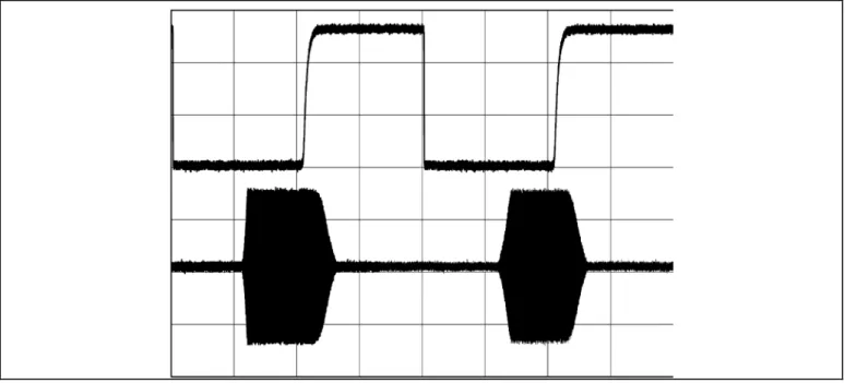
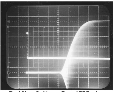
4.7.1 The purpose of the CW Keying Waveform Test is to photograph the first and second dit in a series of dits with the DUT in the VOX and QSK modes. The keying rate is 20 ms on and 20 ms off, a rate that corresponds to 60 WPM using the PARIS standard. A picture will also be taken of any other test conditions that result in any wave shape that is significantly different from the others (more than 10% difference, spikes, etc.).
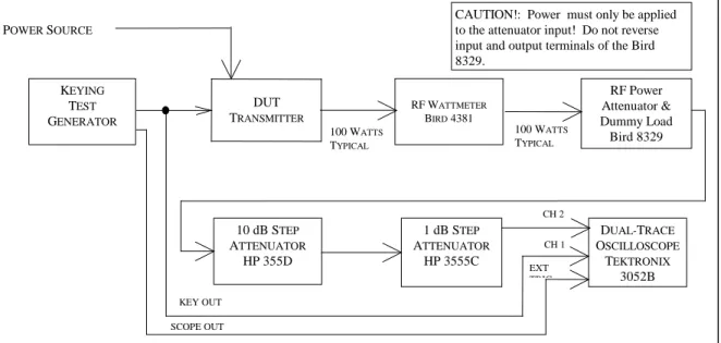
4.7.2 Test hook-up (See Fig. 4-7)
NOTE: If proceeding from the previous SSB Carrier and Unwanted Sideband Test, only the hook-up modifications indicated with a dotted line need to be implemented for this test.
4.7.2.1 With all power switches in the OFF position and the transceiver in the receive mode, connect the following:
Connection Connectors Cable Type
DUT RF OUTPUT to wattmeter INPUT AS Required to type N 50-Ohm coax Wattmeter OUTPUT to Power Attn INPUT Type N to type N 50-Ohm coax Power Attn OUT to 10-dB step INPUT Type N to BNC 50-Ohm coax 10-dB step Attn OUT to 1-dB step IN BNC to BNC 50-Ohm coax 1-dB step Attn OUT to CH2 Scope IN BNC to BNC 50-Ohm coax --- Key Test Gen OUT to Scope EXT TRIG IN BNC to BNC 50-Ohm coax Key Test Gen KEY OUT to DUT KEY IN BNC to As Required 50-Ohm coax XMTR Key Line to Scope CH1 INPUT Probe clip to BNC 10X Probe
Scope GND to XMTR GND As Required As Required
---
Power to DUT As Required As Required
CAUTION!: Power must only be applied to the attenuator input! Do not reverse input and output terminals of the Bird 8329. RF Power Attenuator & Dummy Load Bird 8329 100 WATTS TYPICAL 100 WATTS TYPICAL RF WATTMETER BIRD 4381 KEYING TEST GENERATOR DUT TRANSMITTER POWER SOURCE 10 dB STEP ATTENUATOR HP 355D 1 dB STEP ATTENUATOR HP 3555C DUAL-TRACE OSCILLOSCOPE TEKTRONIX 3052B CH 2 CH 1 EXT TRIG KEY OUT SCOPE OUT
4.7.3 Test Procedure
4.7.3.1 Turn the DUT, RF wattmeter and oscilloscope power switches to ON. Set the following controls:
Instrument Control Position
DUT Mode CW
Band Selector 20 Meters
Frequency 14.020 MHz
XMIT/RCV Receive
Drive or RF Level Maximum
Keying Mode VOX
RF Wattmeter Push-button Mode Select FWD CW
Element As Required
Forward Element Range As Required
10-dB Step Attn Attenuator –40 dB
1-dB Step Attn Attenuator Any
Keying Test Generator OUTPUT OFF
RANGE 1-99 MS KEY DOWN 20 KEY UP 20 Oscilloscope CH1 VOLTS/DIV 500 mV CH1 Coupling DC CH1 Position As Needed CH2 VOLTS/DIV 1 V CH2 Coupling DC CH2 Position As Needed TIME/DIV 10 MS Trigger Coupling DC Trigger Source External Trigger Level As Required
4.7.3.2 Set the keying test generator to ON. Allow all equipment at least 10 minutes warm-up time before proceeding. 4.7.3.3 Tune the DUT, if necessary, exactly per the operator's manual for the 14.250 MHz test frequency. Set for maximum power output.
4.7.3.4 Set the keying test generator OUTPUT to ON. Adjust the oscilloscope for a display trace similar to Fig. 4-7A. Note: If the keying generator pulse train shows capacitive shaping, this is due to the configuration of the DUT’s keying input circuit and should be considered normal. Be sure that the RF-power level of the dit is approximately the same as the carrier level.
4.7.3.5 Capture the first dit and second dit in a string of dits by using the single-trigger mode of the oscilloscope. Turn the keying generator OFF then ON again to facilitate the string of dits. (NOTE: Some transmitters will lose or chop the first dit of a word).
4.7.3.7 Repeat steps 4.7.3.5 and 4.7.3.6 for QSK ON, and any other keying mode deemed appropriate by the Test Engineer. Also photograph the results of any mode of operation that results in a wave shape that is significantly different (>10% difference, spikes, etc.).
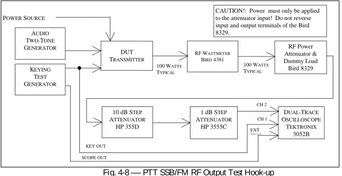
4.8 PTT TO SSB/FM RF OUTPUT TEST
4.8.1 The purpose of the PTT to SSB/FM RF Output Time Test is to determine the key time to RF output delay for the waveform 50% points in the SSB and FM modes. In the SSB mode, audio at a frequency of 700 Hz, and a level within the manufacturer's specified limits, will be applied to the DUT's mic input terminals. The FM mode is tested with an unmodulated carrier.
4.8.2 Test hook-up (See Fig. 4-8)
NOTE: If proceeding from the previous CW Keying Waveform Test, only the hook-up modifications indicated with a dotted line need to be implemented for this test.
4.8.2.1 With all power switches in the OFF position and the transmitter in the receive mode, connect the following:
Connection Connectors Cable Type
DUT RF OUTPUT to Wattmeter INPUT As Required to type N 50-Ohm coax Wattmeter OUTPUT to Power Attn INPUT Type N to type N 50-Ohm coax Power Attn OUT to 10-dB step INPUT Type N to BNC 50-Ohm coax 10-dB step Attn OUT to 1-dB step IN BNC to BNC 50-Ohm coax 1-dB step Attn OUT to CH2 Scope IN BNC to BNC 50-Ohm coax Key Test Gen OUT to Scope EXT TRIG IN BNC to BNC 50-Ohm coax Two-Tone Gen OUT to DUT MIC INPUT Banana to As Required Coax
--- Key Test Gen Key OUT to DUT PTT IN BNC to As Required 50-Ohm coax XMTR PTT Key Line to Scope CH1 IN BNC to BNC 10X Probe
Power to DUT As Required As Required
4.8.3 Test procedure
4.8.3.1 Turn the DUT, RF wattmeter and oscilloscope power switches to ON. Set the following controls:
Instrument Control Position
DUT Mode USB
Band Selector 20 Meters
Frequency 14.250 MHz
XMIT/RCV Receive
DRIVE or RF LEVEL Minimum
VOX Off
RF Wattmeter Mode Select Button FWD PEP
Element As Required
Forward Element Range As Required
10-dB Step Attn Attenuator –40 dB
1-dB Step Attn Attenuator Any
Keying Test Generator OUTPUT OFF
RANGE 1-99 MS
KEY DOWN 20
KEY UP 20
Two-Tone Generator TONE A ON
TONE B OFF HI-Z/LO-Z As Required BALANCE N/A LEVEL Full CCW ATTENUATOR –30 dB Oscilloscope CH1 VOLTS/DIV 500 mV CH1 Coupling DC CH1 Position As Needed
CAUTION!: Power must only be applied to the attenuator input! Do not reverse input and output terminals of the Bird 8329. RF Power Attenuator & Dummy Load Bird 8329 100 WATTS TYPICAL 100 WATTS TYPICAL RF WATTMETER BIRD 4381 KEYING TEST GENERATOR DUT TRANSMITTER POWER SOURCE 10 dB STEP ATTENUATOR HP 355D 1 dB STEP ATTENUATOR HP 3555C DUAL-TRACE OSCILLOSCOPE TEKTRONIX 3052B CH 2 CH 1 EXT TRIG KEY OUT SCOPE OUT AUDIO TWO-TONE GENERATOR
CH2 VOLTS/DIV 1 V
CH2 Coupling DC
CH2 Position As Needed
TIME/DIV 5 MS
Trigger Mode AUTO
Trigger Coupling DC
Trigger Source EXT
Trigger Level As Required
4.8.3.2 Set the Two-Tone and Keying Test Generator power switches to ON. Receiver hiss should be heard; adjust volume to desired level. Allow all equipment at least 10 minutes warm-up time before proceeding to step 4.8.3.3 4.8.3.3 Tune the DUT transmitter, if necessary, exactly per the operator's manual for the 14.250 MHz test frequency. Adjust the two-tone generator OUTPUT level to the manufacturer's specified limit. Set the DUT for maximum rated power output.
4.8.3.4 Turn the keying test generator OUTPUT to ON. Adjust the oscilloscope for a display trace similar to Fig. 4-8A. It may be necessary to reduce the generator keying speed. Be sure that the RF power level of the Dit is approximately the same as the carrier level.
4.8.3.5 Measure the ON and OFF delay times between the 50% points of the keying pulse and the RF output pulse. Take a single sweep. Adjust the oscilloscope’s sweep rate and horizontal position for optimum display results. It is often best to determine the on and off delay times from two different traces. The Trigger Level adjustment can be used to
facilitate an easy transition between ON and off delay traces. Record both values in 4.8.3.5 of the data sheet. Turn off the two-tone and keying test generator outputs.
4.8.3.6 Place the DUT in the FM mode. Repeat paragraphs 4.8.3.3, 4.8.3.4 and 4.8.3.5 for this mode at a test frequency of 29.000 MHz . Record the results in 4.8.3.6 of the data sheet.
4.8.3.7 Repeat step 4.8.3.6 for test frequencies of 52.000 MHz, 146.000 MHz and 440.000 MHz, as appropriate. Fig. 4-8A ── Oscilloscope Trace of RF Envelope
4.9 TRANSM I T/RECEI VE TURN-AROUND TI M E TEST (Transceivers Only)
4.9.1 The purpose of the Transmit/Receive Turn-Around Time Test is to measure the time delay required for a transceiver to switch from transmit to the receive mode.
4.9.2 Test hook-up (See Fig. 4-9)
4.9.2.1 With all power switches in the OFF position and the transceiver in the receive mode, connect the following:
Connection Connectors Cable Type
DUT RF OUTPUT to wattmeter INPUT As Required to type N 50-Ohm coax Wattmeter OUTPUT to Power Attn INPUT Type N to type N 50-Ohm coax Power Attn OUT to 10-dB step INPUT Type N to BNC 50-Ohm coax 10-dB step Attn OUT to 1-dB step IN BNC to BNC 50-Ohm coax --- 1-dB step Attn IN to Signal Gen RF OUT BNC to Type N 50-Ohm coax DUT Audio OUT to Scope CH2 INPUT As Required 10X or 1X Probe --- Key Gen Scope OUT to Scope EXT TRIG IN BNC to BNC 50-Ohm coax Key Test Gen Key OUT to PTT Key IN BNC to As Req 50-Ohm coax
XMTR PTT Line to Scope CH1 INPUT Probe clip to BNC 10X Probe
Connection Connectors Cable Type
Two-Tone Gen OUT to DUT MIC INPUT Banana to As Required Coax
Power to DUT As Required As Required
4.9.3 Test procedure
4.9.3.1 Turn the DUT, RF wattmeter and oscilloscope power switches to ON. Set the following controls:
Instrument Control Position
DUT Mode USB
Frequency 14.250 MHz
XMIT/RCV Receive
AGC ON (Fastest available)
Squelch OFF
RF Wattmeter Push-button Mode Select FWD PEP
Element As Required
Forward Element Range As Required
10-dB Step Attn Attenuator 120 dB
1-dB Step Attn Attenuator 0 dB
Keying Test Generator OUTPUT EN OFF
RANGE 1-99 ms KEY DOWN 50 ms KEY UP 50 ms Oscilloscope CH1 VOLTS/DIV 0.5 V CH1 Coupling DC CH2 VOLTS/DIV 1 V CH2 Coupling DC TIME/DIV 5 ms Trigger Coupling DC
Trigger Source EXT
Two-Tone Generator TONE A ON
TONE B OFF
CAUTION!: Power must only be applied to the attenuator input! Do not reverse input and output terminals of the Bird 8329. RF Power Attenuator & Dummy Load Bird 8329 100 WATTS TYPICAL 100 WATTS TYPICAL RF WATTMETER BIRD 4381 KEYING TEST GENERATOR DUT TRANSMITTER POWER SOURCE 10 dB STEP ATTENUATOR HP 355D 1 dB STEP ATTENUATOR HP 3555C DUAL-TRACE OSCILLOSCOPE TEKTRONIX 3052B CH 2 CH 1 EXT TRIG KEY OUT SCOPE OUT AUDIO TWO-TONE GENERATOR SIGNAL GENERATOR MARCONI 2041 AUDIO OUT DO NOT EXCEED -40 dBm!
HI-Z/LO-Z As Required
BALANCE N/A
LEVEL FULL CCW
ATTENUATOR –30 dB
RF Generator FREQUENCY TUNE 14.250 MHz
OUT LEVEL +10 dBm
RF ON
AM OFF
FM OFF
4.9.3.2 (If proceeding from the previous PTT to SSB RF Output Time Test, this paragraph may be skipped). Set the Two-Tone and Keying Test Generator power switches to ON. Receiver hiss should be heard; adjust the volume to the desired level. Allow all equipment at least 10 minutes warm-up time before proceeding to step 4.9.3.3.
CAUTION: Reverse power to the RF signal generator at no time should exceed -40 dBm (approx. 2 Vrms).
Shut-down of the instrument may result.
4.9.3.3 Reduce the step attenuators until the signal is heard and a deflection can be observed on the S meter. Tune the receiver for maximum S meter indication. Reduce the RF step attenuators until the receiver S meter indicates an S9 signal. If the DUT does not have an S Meter, then set for a 50 µV input to the DUT.
4.9.3.4 Tune the transmitter, if necessary, exactly per the operator’s manual for the 14.250 MHz test frequency. Turn on the two-tone generator and set the A tone switch to ON. With the DUT in the USB mode, set the generator LEVEL and ATTENUATOR controls for the maximum audio input level as specified by the DUT manufacturer. specified by the manufacturer. Unkey the transmitter and turn
the keying test generator 4.9.3.5 Key the transmitter and set for the maximum power as ON. Adjust the
oscilloscope settings (including sweep rate) as required for an optimum display trace as shown in Fig. 4-9A. If the audio output is not visible at all on the oscilloscope it will be necessary to increase the keying test generator KEY-UP and KEY-DOWN time. Measure and record the time it takes to go from PTT key-up to 50% audio output. Set the keying test generator to OFF.
4.9.3.6 Repeat step 4.9.3.5 for other AGC options, if available, and a 20 dB decrease in signal strength. Check the appropriate box in 4.9.3.6 of the data sheet if no significant deviation is observed. Record the space provided any significant deviation.
4.9.3.7 AMTOR requires the transceiver audio to reach 50% of its full value in 35 ms or less. Determine the AMTOR suitability and record on the data sheet.
4.10 KEYER SPEED AND SI DETONE FREQUENCY TEST (For units having an internal keyer.)
4.10.1 The purpose of this test is to measure the transmitter’s internal keyer speed range and sidetone frequency range.
4.10.2 Test hook-up (See Fig. 4-10)
4.10.2.1 With all power switches in the OFF position and the transceiver in the receive mode, connect the following:
Connection Connectors Cable Type
DUT RF OUTPUT to wattmeter INPUT As Required to type N 50-Ohm coax Wattmeter OUTPUT to Power Attn INPUT Type N to type N 50-Ohm coax Power Attn OUT to Scope CH1 INPUT BNC to Type N 50-Ohm coax DUT Audio OUT to Scope CH2 INPUT As Required 50-Ohm coax DUT Audio OUT to 10 dB step Attn IN As Required to BNC 50-Ohm coax (10W or greater power rating)
10 dB step Attn OUT to Freq Counter IN BNC to BNC 50-Ohm coax DUT Audio OUT to HI-Z Amp / 8 Ohm load As Required to BNC 50-Ohm coax XMTR Key Input to Telegraph Key As Required to Test Clips Any
Power to DUT As Required As Required
4.10.3 Test procedure
4.10.3.1 Turn the DUT, RF wattmeter and oscilloscope power switches to ON. Set the following controls:
CAUTION!: Power must only be applied to the attenuator input! Do not reverse input and output terminals of the Bird 8329 RF Power Attenuator & Dummy Load Bird 8329 100 WATTS TYPICAL 100 WATTS TYPICAL RF WATTMETER BIRD 4381 TELEGRAPH KEY DUT TRANSMITTER POWER SOURCE 10 dB STEP ATTENUATOR TEKTRONICS FREQUENCY COUNTER HP-5351B DO NOT EXCEED 0 dBm! DUAL-TRACE OSCILLOSCOPE TEKTRONIX 3052B AUDIO OUT CH 1 CH 2 HI-Z MONITOR AMP
Instrument Control Position
DUT Mode USB
Frequency 14.250 MHz
XMIT/RCV Receive
AGC N/A
Squelch OFF
RF Wattmeter Push-button Mode Select FWD PEP
Element As Required
Forward Element Range As Required
10-dB Step Attn Attenuator –40 dB
1-dB Step Attn Attenuator 0 dB
Oscilloscope CH1 VOLTS/DIV 0.5 V CH1 Coupling DC CH1 Position As Needed CH2 VOLTS/DIV 1 V CH2 Coupling DC CH2 Position As Needed TIME/DIV 5 ms Trigger Coupling DC Trigger Source CH1
Trigger Level As Required
4.10.3.2 (If proceeding from the previous Turnaround Time Test, this paragraph may be skipped). Receiver hiss should be heard; adjust the volume to the desired level. Allow all equipment at least 10 minutes warm-up time before proceeding to step 4.10.3.3.
4.10.3.3 Key the transmitter. Set the sidetone level for comfortable listening level. Adjust the step attenuators and oscilloscope controls for optimum display. Send a series of dits and then a series of dashes. Verify the dashes are three times longer in duration than the dits. Measure and record any significant deviation from the standard 3 to 1 ratio.
4.10.3.4 With keyer speed still set to minimum, send a series of dits and take a trace in the storage mode. Measure the time duration from the leading edge of a dit to the leading edge of the next. This duration is equivalent to two dits (one dit plus a dit space). Adjust the oscilloscope controls as required to obtain an optimum trace. Divide the measured time by (in ms) into 2400 to obtain the equivalent code speed (in WPM):
Code Speed in WPM = 1200 / Duration of Single Dit in ms Record on Data Sheet. 4.10.3.5 Set keyer speed to maximum and repeat step 4.10.3.4.
4.10.3.6 Set keyer speed to center or the default position and repeat step 4.10.3.4.
4.10.3.7 Adjust the Frequency Counter Step Attenuators for minimum positive indication. Measure the initial default sidetone frequency . Reduce the sidetone for minimum frequency and measure again. Increase to maximum sidetone frequency and repeat. Record both all three frequencies on Data Sheet.
4.11 COM POSI TE NOI SE TEST
4.11.1 The purpose of the Composite-Noise Test is to observe and measure the phase and amplitude noise, as well as any spurious signals generated by the DUT transmitter. Since phase noise is the primary noise component in any well-designed transmitter, it can be assumed, therefore, that almost all the noise observed during this test is phase noise.
4.11.1.1 This measurement is accomplished with the use of an integrated HP model 11848A phase noise test set that consists of a control box (phase discriminator, phase shift network, DC tuning voltage control, and analyzer outputs), HP 3561A FFT-based dynamic signal analyzer, HP 3563E (or 3562A) microwave spectrum analyzer, and as needed, an oscilloscope (for assistance in establishing zero beat). Measurements are accomplished by computer software run on the 486 computer. Additionally, an appropriate low-noise reference oscillator that can be tuned via DC is also necessary.
4.11.2 Test Hook-up (See Fig. 4-11).
4.11.2.1 With all power switches in the OFF position and the transceiver in the receive mode, connect the following:
Connection Connectors Cable Type*
DUT RF OUTPUT to wattmeter INPUT As Required to type N 50-Ohm coax Wattmeter OUTPUT to Power Attn INPUT Type N to type N 50-Ohm coax Power Attn OUT to 10-dB step INPUT Type N to BNC 50-Ohm coax 10-dB step Attn OUT to 1-dB step IN BNC to BNC 50-Ohm coax 1-dB step Attn OUT to HP-11848A to BNC to BNC 50-Ohm coax “Right” Phase Detector IN
Ref. Oscillator OUT to HP-11848A BNC to BNC 50-Ohm coax “Left” Phase Detector IN
HP-11848A Tuning voltage to Test BNC to BNC or clip leads As Required HP-11848A Phase Detector Output to BNC to BNC 50-Ohm coax HP-3561A FFT Signal Analyzer
HP-11848 Spectrum Analyzer OUT to BNC to BNC 50-Ohm coax HP-8563 E Spectrum Analyzer
Power to DUT As Required As Required
HP-11848A Aux Monitor OUT to BNC to BNC 50-Ohm coax TDS-3052B Oscilloscope CH 1 IN
*NOTE: Composite noise setup is very sensitive to environment noise. Use of common-mode ferrite chokes may be required if test fixture problems are encountered as described in the procedure for this test.
4.11.3 Test procedure
4.11.3.1 Turn the DUT, RF wattmeter, test system, spectrum analyzer power, and reference oscillator switches to ON. Set the following controls:
Instrument Control Position
DUT Mode CW
Band Selector 20 Meters
Frequency 14.025 MHz
Output Power 30-50 %
RF Wattmeter Push-button Mode Select FWD CW
Element As Required
Forward Element Range As Required
10-dB Step Attn Attenuator As required for +15 dBm
1-dB Step Attn Attenuator Any
Reference Oscillator FREQUENCY 14.025 MHz
4.11.3.2 Allow all equipment, including the test oscillator, at least 15 minutes warm-up time before proceeding. TURN OFF all non essential test equipment and overhead fluorescent lights. Use the incandescent lighting.
4.11.3.3 Check the manufacturer’s specification of the transmitting duty cycle. If not stated, set the power output to 30 watts for a 100 watt maximum transmitter, or 50 watts for a 200 watt maximum transmitter. The test will take about 15 minutes; do not exceed manufacturer’s duty cycle
4.11.3.4 Turn on the control computer, allow it to complete the boot and program start processes, then step through the menu system to set the initial test frequency and VFO tune ranges. On the menu, the test frequency has a scientific format; example: 14.025E+6 (14.025 x 10 to the 6th power). For the Wenzel crystal oscillators, use 14.025 MHz, a VCO tune center voltage of approximately 5 and a tune voltage range of +/-5 V. For the Marconi/IFR 1041 signal generators, set the tune center voltage to 0 and a tuning range +/-5V. All other parameters should be ok at their initial values. RF POWER ATTENUATOR BIRD 8329 10 dB STEP ATTENUATOR HP 355D 1 dB STEP ATTENUATOR HP 355C RF WATTMETER BIRD 4381 PHASE DET./ SYSTEM CONTROLLER HP3561A FFT ANALYZER HP8563E SPECTRUM ANALYZER TRANSMITTER
PHASE NOISE TEST SET
LOW NOISE VARIABLE CRYSTAL OSC TEST CONTROL COMPUTER
4.11.3.5 Key the transmitter and adjust the frequency of the DUT to be approximately 1 Hz or less from the
frequency of the reference oscillator. Use an oscilloscope , if necessary, to remove any undulating shape on the screen of the noise output. The two frequencies must not be equal or a phenomenon known as phase roll may result, and, if much greater than 2 Hz apart, the software will not run and will show an error message. The tuning voltage of the test oscillator may be adjusted slightly in the software if the transmitter tuning cannot be brought less than 1 Hz. The idea is to get as close as possible, without being identical. The signal should be unreadable and only the noise clearly visible on the analyzer display before proceeding to the next step. Un-key the transmitter.
4.11.3.6 To measure the Phase Noise, key the transmitter and run the program. After about three minutes, you should see a graph of the composite noise forming on the PC screen. After 15 minutes or so, the process will be complete and the file is saved as a type .PCX file. Before saving the file, press “M” and omit the spurs (red lines on the graph). Copy the file to disc.
4.11.3.7 Repeat steps 4.11.3.4 through 4.11.3.6 with a test frequency of 50.020 MHz. With this test, you will replace the Test Oscillator with the IFR 2041 Signal Generator in the “Low Noise” mode. Set the following controls on the IFR2041:
External 1 to “DC Coupling”
Deviation to 3 kHz, MODULATION ENABLED RF Level to +13 dBm
Frequency to 50.020
RF Output to “Left” Phase Detector Input External 1 to Tune Voltage Output
Be sure to change the following on the software menu: Frequency to 50.020E+6
Detector Frequency is + 6 volts Center Tune Volts is 0.0 volts Tune Range is 6 volts.
V. RECEI VER TESTS
5.0.1 As shown in the Table of Contents, there are 17 Receiver tests outlined in this chapter. They have been arranged, just as in the previous transmitter tests, to minimize the required level and frequency of hook-up changes and modifications. Each hook-up, however, is shown complete with all changes from the previous test clearly indicated. A block diagram accompanies each hook-up and any changes from the previous test are shown within a dotted rectangle. This affords the flexibility to easily start anywhere and perform these tests in any desired order. 5.0.2 Before performing any receiver testing, it is essential for the test engineer to be completely familiar with the Device Under Test (DUT) and the test equipment that will be used. The RF output of a transceiver will damage the test equipment and therefore, it is essential never to accidentally key the transmitter while performing these tests! Completely disable the transmitter if at all possible and set all RF output controls to minimum, reduce drive,
disconnect the telegraph key, etc. The receiver must be operated in a manner exactly as specified by the manufacturer. Any test that would cause equipment to be operated in a manner inconsistent with its operating manual must be modified accordingly.
5.0.2.1 Other considerations are as follows:
1) The RF Generator output must not exceed –14 dBm when using the Hybrid Combiner. This restriction is an effort to minimize intermodulation in the combiner and signal generators.
2) The level of input to the receiver should not exceed +10 dBm or the manufacturer's specification, whichever is less.
3) Read and understand all pertinent manuals before operating any laboratory instrument or the DUT receiver.
4) The testing should be conducted in a relatively RF free environment. If an RF source is in close proximity to the testing site, an RF screen room should be used.
5) If a preamp is available, each test must be performed with each level of the preamp and without the preamp.
6) If the audio output impedance is not 8 Ohms, select the appropriate load resistance on the HI-Z Audio Amplifier.
5.1 NOI SE FLOOR TEST
5.1.1 The purpose of the Noise Floor Test (also known as “Minimum Discernible Signal” or MDS) is to determine the level of signal input to the receiver that will produce an audio output where the power in the signal is equal to the power in the noise (S + N = N + 3 dB). The test is conducted with the receiver in the CW mode using the 500 Hz, or closest available IF filter (or audio filters where IF filters are not available. For receivers that have appropriate IF filters, all audio filtering is disabled.) Set the AGC to the OFF position if possible. The test is performed frequencies of 1.020 MHz, 3.520 MHz, 14.020 MHz, 50.020 MHz, 144.020 MHz and 432.020 MHz. For the expanded set of tests, this test is performed on all available amateur bands, 20 kHz above the lower band edge.
5.1.2 Test hook-up (See Fig. 5-1)
5.1.2.1 With all power switches in the OFF position, the transmitter function disabled to the fullest extent possible and the Generator RF switch OFF, connect the following:
Connection Connectors Cable Type
Signal Gen OUTPUT to 10-dB Step Attn INPUT BNC to BNC 50-Ohm Coax 10-dB Step Attn OUTPUT to DUT RF INPUT BNC to As Required 50-Ohm Coax DUT AUDIO OUT to Dist/Audio Meter IN As Required to BNC 50-Ohm Coax 8-Ohm Load/HI-Z Amp Across Dist/Audio As Required As Required Meter Input
Power Source to DUT Power Input As Required As Required
RF SIGNAL GENERATOR MARCONI 2041 10 dB STEP ATTENUATOR HP 355D 1 dB STEP ATTENUATOR HP 355C DUT RECEIVER AUDIO/ DISTORTION METER HP 339A HI-Z MONITOR AMP
5.1.3 Test Procedure
5.1.3.1 Turn the DUT and all test equipment power switches to ON. If the DUT does not cover 1.020 MHz, proceed directly to the second test frequency of 3.520 MHz. Set the following controls:
Instrument Control Position
DUT Mode CW
Band Selector As Required for 1.020 MHz Frequency 1.020 MHz
XMIT/RCV RCV
DRIVE or RF LEVEL Minimum
IF Filters 500 Hz or Closest Available
AGC OFF
Preamplifier OFF
10 dB Step Attn Attenuator 0 dB
RF Generator CARRIER FREQ 1.020 MHz
RF LEVEL –110 dBm
NOISE MODE (UTIL) LOW NOISE
Audio/Distortion Meter FUNCTION REL LEVEL
RELATIVE ADJUST Center Rotation FILTERS All Off (Out) INPUT RANGE 30 V
INPUT/GND SELECT DIS (Center) METER RESPONSE NORM
5.1.3.2 Receiver hiss should be heard. Adjust the volume of the DUT and HI-Z monitor amp to the desired level. Allow all equipment at least 10 minutes warm-up time before proceeding to step 5.1.3.3.
5.1.3.3 Verify the RF Generator Output frequency has remained at 1.020 MHz. Reset if necessary.
5.1.3.4 Tune the receiver for 1.020 MHz. Adjust the INPUT RANGE and RELATIVE ADJUST controls as required to maintain approximately a mid-scale meter indication while carefully tuning the receiver for peak signal response. (Rotate the Generator OUTPUT LEVEL control as required until the signal is just heard in the receiver.)
5.1.3.5 Set the RF Generator RF switch to OFF. Decrease the Audio Meter INPUT RANGE until the meter indication is near mid-scale and the two lights above this control are out. Adjust the audio meter RELATIVE ADJUST control until the audio meter reads –6 dB on the upper scale. (Adjust the INPUT RANGE control one step in either direction if necessary.)
5.1.3.6 Set the RF Generator RF switch to ON. Rotate the generator OUTPUT LEVEL control to produce an audio meter reading of –3 dB. Ensure that the DUT is tuned for peak response.
5.1.3.7 Check to ensure that the Generator frequency is still at 1.020 MHz. Set the RF Generator RF to OFF. The audio meter should return to –6 dB. Turn the RF back on and the meter should again indicate –3 dB.
5.1.3.8 Determine the noise floor (MDS) of the receiver by computing the sum of the RF generator output in dBm and the 10 dB step attenuator. (NOTE: Be sure to include any additional attenuation you may have included in the line between the generator and the DUT.) Record on the Data Sheet.
Example: a) The RF generator is set for –128.6 dBm output. b) The step attenuators are set for –10 dB.
c) The receiver MDS, therefore, is: –128.6 – 10 = –138.6 dBm
5.1.3.9 Repeat steps 5.1.3.4 to 5.1.3.8 with DUT preamplifier set to ON.
5.1.3.10 Re-set the generator output level to –110 dBm. Repeat paragraphs 5.1.3.3 to 5.1.3.9 for a test frequency of 3.520 MHz.
5.1.3.11 Repeat step 5.1.3.10 for a test frequency of 14.020 MHz.
5.1.3.12 Repeat step 5.1.3.10 for test frequencies of 50.020 MHz, 144.020 MHz and 432.020 MHz, as applicable to the DUT.
5.2 AM RECEI VE SENSI TI VI TY TEST
5.2.1 The purpose of the AM receive Sensitivity Test is to determine the level of an AM signal, 30% modulated at 1 kHz, that will produce a tone 10 dB above the noise level (MDS) of the DUT. Two frequencies, 1.020 MHz and 3.800 MHz are used for this test.
5.2.2 Test hook-up (See Fig. 5-2)
NOTE: If proceeding from the MDS Test, no hook-up changes are required. Proceed to step 5.2.3. 5.2.2.1 With all power switches in the OFF position and the transmitter function disabled to the fullest extent possible, connect the following:
Connection Connectors Cable Type
Signal Gen OUTPUT to 10-dB Step Attn INPUT BNC to BNC 50-Ohm Coax 10-dB Step Attn OUTPUT to DUT RF INPUT BNC to As Required 50-Ohm Coax DUT Audio OUTPUT to Dist/Audio Meter As Required to BNC 50-Ohm Coax INPUT
8 Ohm Load/HI-Z Amp Across Dist/Audio As Required As Required Meter INPUT
Power Source to DUT Power Input As Required As Required
RF SIGNAL GENERATOR MARCONI 2041 10 dB STEP ATTENUATOR HP 355D 1 dB STEP ATTENUATOR HP 355C DUT RECEIVER AUDIO/ DISTORTION METER HP 339A HI-Z MONITOR AMP
Fig. 5-2. AM Receive Sensitivity Test Hook-Up 5.2.3 Test Procedure
5.2.3.1 Turn the DUT and all test equipment power switches to ON. If the DUT does not cover 1.020 MHz, proceed directly to the second test frequency of 3.800 MHz. Set the following controls:
Instrument Control Position
DUT Mode AM
Band Selector As Required for 1.020 MHz Frequency 1.020 MHz
XMIT/RCV RCV
DRIVE or RF LEVEL Minimum
AGC OFF Preamplifier OFF DUT Audio Filter(s) Disabled
10-dB Step Attn Attenuator 0 dB
RF Generator CARRIER FREQ 1.020 MHz
RF LEVEL –110 dBm CARR ON-OFF ON AM ON AM DEPTH 30% Modulation Frequency 1000 Hz FM OFF
NOISE MODE LOW NOISE MODE
Audio/Distortion Meter FUNCTION REL. LEVEL
RELATIVE ADJUST Center Rotation FILTERS All OFF (Out) INPUT RANGE 30 V
INPUT/GND SELECT DIS (Center) METER RESPONSE NORM
5.2.3.2 Receiver hiss should be heard. Adjust the DUT and HI-Z monitor amp volume to the desired level. Allow all equipment at least 10 minutes warm-up time before proceeding to step 5.2.3.3.
5.2.3.3 Tune the receiver for 1.020 MHz. Adjust the Audio Meter INPUT RANGE control as required to maintain approximately a mid-scale meter indication while carefully tuning the receiver for peak signal response. (If necessary, adjust the Generator OUTPUT LEVEL as required until the signal is just heard in the receiver.)
5.2.3.4 Set the RF Generator modulation control switch to OFF. Decrease the Audio Meter INPUT RANGE until the meter indication is near mid-scale and the two lights above this control are out. Adjust the audio meter RELATIVE ADJUST control until the audio meter reads –11 dB on the upper scale. (Adjust the INPUT RANGE control one step in either direction if necessary.)
5.2.3.5 Set the RF Generator RF switch to ON. Adjust the setting of the generator RF OUTPUT LEVEL to produce an audio meter reading of –1 dB +/-.5 dB. Recheck for peak response using the audio meter.
5.2.3.6 Check to ensure that the Generator frequency is still at 1.020 MHz. Set the RF Generator modulation to OFF. The audio meter should return to –11 dB. Turn the modulation back on and the meter should again indicate
–1 dB.
NOTE: The following measurement method is often better, especially in cases where the DUT AGC cannot be disabled. The Audio Meter settings are the same as for the FM SINAD Test except th