Pre-Symposium Excursion Guidebook
Keuruu – Jormua – Taivalkoski – Siurua – Tervola
Sept. 21-25, 2012
Edited by2
Pesonen, L. J., Mertanen, S., Sangchan, P. and Koljonen, E. (editors), 2012.
Supercontinent Symposium 2012 – Pre-Excursion Guidebook. Geological
Survey of Finland, Espoo, Finland, 100 pp.
Cover images:
Up left: Shatter cone of Keurusselkä (Stop 1) by L. J. Pesonen;
Below left: mafic dyke of Taivalkoski (Stop 8) by M. Melamies;
Below right: Rantamaa stromatolites (Stop 12) by V. Perttunen
ISBN 978-952-217-202-0
Geological Survey of Finland
Espoo 2012
3
Preface
This excursion guidebook provides a background for the seven geological landmark sites in Finland which will be visited during the pre-symposium (Supercontinents 2012) excursion. During the four excursion days (Sept. 22-25, 2012) twelve stops constitute the excursion programme. Descriptions of the stops are preceded by a general introduction to the topics followed by geology and geophysics of the stops in the framework of Precambrian supercontinents - the topic of the symposium. The guidebook is organized in day-by-day principle. In addition to geology, short descriptions of Finland and in particular the city of Helsinki and the other cities, towns and villages we are passing through, is provided. For those who are not familiar with the geology of the Baltic or Fennoscandian Shield a short description is added to provide a framework for the tour.
This guidebook is edited by Lauri J. Pesonen, Satu Mertanen, Pathamawan Sangchan and Ella Koljonen. Each chapter has their own editors including, in addition to the afore mentioned, Robert Klein and Selen Raiskila (Keurusselkä), Asko Kontinen (Jormua), Jouni Vuollo and Johanna Salminen (Taivalkoski), Hannu Huhma and Katja Lalli (Siurua) and Juha Karhu, Nina Hendriksson and Vesa Perttunen (Rantamaa).
Several cities, towns, and communes have supported us, notably, Helsinki, Keuruu, Lappajärvi, Rovaniemi and Tervola. We thank all of them. We also thank Kari Jääskeläinen, Tuire Laine, Toni Veikkolainen, Harri Matikainen, Markku Montonen and Tommi Vuorinen for their help in preparing this guidebook and the excursion. The publishing of the guidebook was made possible with the help of the Geological Survey of Finland.
Welcome to the Excursion of the Supercontinent Symposium 2012!
Kumpula, Sept. 19, 2012
Lauri J. Pesonen
Solid Earth Geophysics Laboratory University of Helsinki
5
Pre-Symposium Excursion Guidebook
Contents
page
Excursion route
6
Finland in focus
7
I Short overview of the geology of the Fennoscandian Shield
10
II Impact cratering: a short overview with Finland as a focus
15
III Day “0”, Friday, Sept. 21, 2012
Helsinki: ”The Daughter of the Baltic Sea”
20
Excursion poster
23
IV Day 1, Saturday, Sept. 22, 2012: Helsinki-Lappajärvi (bus)
Keurusselkä impact structure (Stop 1)
25
Paleomagnetism and petrophysics of the Keuruu dykes
42
(Stops 2 and 3)
City of Keuruu and Lappajärvi town
55
V Day 2, Sunday, Sept. 23, 2012: Lappajärvi-Kajaani (bus)
Sights between Lappajärvi and Jormua
58
Jormua ophiolite complex (Stops 4, 5 and 6)
59
City of Kajaani
68
VI Day 3, Monday, Sept. 24, 2012: Kajaani- Rovaniemi (bus)
Saarijärvi impact structure (en route, Stop 7)
70
Taivalkoski mafic dykes (Stops 8, 9 and 10)
75
Siurua trondhjemite gneiss (Stop 11)
89
Taivalkoski town
93
VII Day 4, Tuesday, Sept. 25, 2012: Rovaniemi- Oulu-Helsinki (bus & flight)
Rantamaa formation (Stop 12)
95
Rovaniemi and Pohtimolampi
100
6
7
8
Finland in focus
The Republic of Finland (i.e. “Suomi”) is an independent (since 1917) country in northern Europe at the shores of the Baltic Sea. Finland is part of Nordic Countries and European Union. The country is surrounded by neighbors such as Russia in the east, Norway in the north, Sweden in the west and across the Gulf of Finland in the south is Estonia. Ahvenanmaa, an archipelago in the Baltic Sea, is part of Finland but has autonomy and is demilitarized.
Figure 1. Geographical location of Finland within the European Union. Finland is outlined by black contour. Climatically, Finland is situated in the northern part of the temperate zone of the world. It is also part of the Boreal forest zone or Taiga.
Finland has a relatively low population density (18 inhabitants per km2) and most of them live in the southern and mid parts of the country. There are two official languages, Finnish and Swedish. Some 5.4% of the 5.4 million people living in Finland speak Swedish as their mother tongue and generally they live in the south or southwestern areas of Finland.
9
Finland in figures
Population
5.4 million with annual growth rate 0.5%. Life expectancy: men 76.5, women 83.2 yrs. Average household size: 2.1 persons. 55% of the households live in single-family houses. 44% in apartment blocks. 84.4% are urban-dwellers, with 1 million in the Helsinki area, which includes Espoo and Vantaa.
Other major cities in Finland include Tampere, Turku, Oulu and Jyväskylä.
Religion: 78% are Lutheran; 1% Orthodox. Education: 78% of the population aged 25 to 64 have completed upper secondary or tertiary education and 35% (the highest percentage in the EU countries) have university or other tertiary qualifications.
Wired: 82% of Finnish households own a personal computer and 70% broadband; 92% own a digital television and 98% of households have cell phones.
Government
Sovereign parliamentary republic since 1917. From 1809-1917, autonomous Grand Duchy within the Russian Empire; before that part of the Kingdom of Sweden for centuries.
The president is elected every six years. The new president of Finland Sauli Niinistö took office in March 2012.
The 200 members of Parliament are elected for four-year terms. The most recent general election produced the following result: National Coalition Party 44; Social
Democratic Party 42; The Finns 39; Finnish Centre 35 seats; Left Alliance 14; Greens 10; Swedish People’s Party 6; Åland 1.
Finland has been a member of the European Union since January 1995.
Working life and Economy
85% of women aged 25-54 are employed outside the home. Average monthly earnings (2011): men 3487 €, women 2841 €. Current unemployment rate 8.4%.
GDP 2011; 192 billion euros. Annual inflation rate (2012): 3.1%. Currency: Euro €.
Area
390 920 km2 of which 9% is fresh water; land area is 303 909 km2. There are 188 000 lakes, 6% of the land is under cultivation with barley and oats the main crops. Forests (mainly pine and spruce) cover 68% of the country.
10
I Short overview of the geology of the
Fennoscandian Shield
11
Introduction
The Fennoscandian (or Baltic) Shield represents the largest outcropping domain of Precambrian bedrock in Europe, covering more than a million km2 throughout Norway, Sweden, Finland, Bornholm island of Denmark and northwestern Russia (Fig.2a).
Figure 2. (A) Precambrian continental cratons of the world are outlined in yellow shading (Mertanen and Pesonen, 2012). Fennoscandia or Baltica is shown with a black outline. (B) Major geological events in the Fennoscandian Shield including magmatic dyking events, ages of kimberlite clan rocks, meteorite impacts and deposition of sedimentary basins. Modified after Kohonen and Rämö (2005).
The bedrock of Finland belongs to the East European Craton (EEC) of northern and eastern Europe and northwestern Russia. Precambrian crystalline rocks crop out only in the northern and southwestern parts of the craton, in the Fennoscandian and Ukrainian shields, respectively; elsewhere they are covered by platform sediments. In Sweden and Norway, the Fennoscandian Shield is delimited by the Caledonides. In Estonia in the south and Russia in the south-east, the Precambrian bedrock plunges at a shallow angle under Phanerozoic sedimentary rocks.
The most important events during the evolution of the Finnish bedrock occurred at 2800-2700 Ma and 1900-1800 Ma (Fig. 2b). In those times, continental crust was segregated from the Earth’s mantle in two major (probably multiphase) orogenies. The resultant Archean and Paleoproterozoic crust of Finland is divided into 25 areas with characteristic lithologic units (Fig. 3). This Chapter gives an overview of Finland’s bedrock and its evolution from the Mesoarchean to the present time.
Finland forms about one third of the Fennoscandian Shield which crops out among younger sedimentary rocks and the Caledonian mountain belt. By age, it can be divided into four main areas: the Archean, the Svecofennian and the Sveconorwegian domains, and the Transscandinavian igneous belt lying between the latter two (Fig. 3). The northern and eastern parts of Finland belong to the >2.5 Ga Archean block, divided usually into the Kola
12
and Karelia cratons, while the central and southern parts comprise the Paleoproterozoic
Svecofennian rocks, ca. 1.93-1.80 Ga in age. Only a small part of the Finnish bedrock is younger than 1.8 Ga: the most significant of the younger formations are the 1.65-1.54 Ga
rapakivi granites and associate gabbros, anorthosites and dykes. After the intrusion of the rapakivi batholiths no major magmatism, except a few dyking events (1.26 Ga, 1.12 Ga and 1.05 Ga), has occurred in Finland. Considerable graben formation took place during the Mesoproterozoic and at least southern Finland was covered by Paleoproterozoic-Mesozoic sediments.
Figure 3 gives an outline of the various “block” names used for the EEC and Fennoscandian Shield. The dotted line shows the excursion route, which starts from Paleoproterozoic rocks (Days 1-2), traverses shortly to the Archean (Karelian craton) rocks in North Finland (Day 3) and ends again in Paleoproterozoic area (Day 4).
Figure 3. A) Crustal segments of the East European Craton. FS – Fennoscandian Shield; US – Ukrainian Shield. B) Pre-1.92 Ga crustal components and major terranes/units in the Fennoscandian Shield. Exposed and hidden pre-1.92 Ga components are outlined with a broken line; juvenile crust, crust without known mantle separation age or crust dominated by accreted sediments is shown in white. C) Major tectonic units of the Fennoscandian Shield. D) Major geological units with Paleo-proterozoic and younger boundaries. The dotted line denoted the excursion route. Modified after Gorbatschev and Bogdanova (1993) and Lahtinen et al. (2005).
13
Geophysics along the excursion route
The excursion traverses several remarkable geophysical anomalies in Finland. Figure 4 shows the (a) aeromagnetic, (b) Bouguer gravity, (c) earthquake activity with land-uplift and (d) Moho-depth maps of Finland.
Diabase dyke swarms (Fig. 5), kimberlites and alkaline dykes provide useful information concerning crustal tectonics and supercontinent reconstructions, since dykes of different ages occur within sedimentary basins, greenstone belts, and gneissose to granitic shield areas.
Figure 4. Major Geophysical anomalies in Finland along the excursion route. A) Aeromagnetic, courtesy by J. Korhonen, GTK, B) Bouguer gravity, courtesy by S. Elo, GTK, C) Earthquake activity with land uplift contours and D) Moho depth in Finland (Heikkinen, 2012).
A B
C
D
14
Figure 5. A) Simplified map of mafic dyke swarms of Finland after Aro and Laitakari (1987). The excursion route has been schematically drawn. B) Updated Fennoscandian dyke map by J. Vuollo (GTK).
15
16
Introduction
Impact cratering is one of the most important surface-modifying processes on the Earth. Especially large meteorite impact events are the cause of major crustal deformation with important economic mineral and hydrocarbon deposits. Rapidly radiating shock pressures in target rocks may produce e.g. rock melting (≥ 60 GPa) with post-shock temperatures up to 2000°C, diaplectic glass phases (30-45 GPa), high-pressure minerals (12-30 GPa) and planar deformation features (PDFs) in quartz (10-25 GPa) (French and Koeberl, 2010). Shatter cones, which are striated conical structures in rock formations, occur usually at lower pressures (1-5 GPa; up to 45 GPa) and are coupled with extensive fracturing of the target rock notably in the central uplift area. The impact processes also form breccias, suevites, pseudotachylite veins and ejecta deposits, which are very abundant in larger impact craters. Most of the subcrater breccias are formed late in the cratering stage at relatively low shock pressures (< 1 GPa) lacking distinctive features of shock metamorphism.
The Earth has been covered by a comparable number of impact scars, but due to active geological processes, such as plate tectonics, weathering and erosion etc, the number of preserved and recognized impact craters on the Earth is limited. Nevertheless, the study of the impact structures on the Earth provides a method to understand the evolution of our solar system planetary geology!
Approximately 180 impact structures have been presently confirmed on the Earth (Earth Impact Database 2012). Fennoscandia is statistically one of the most densely crater-populated parts of the Earth (Dypvik et al. 2008) as most of the craters are exposed. Altogether, 31 impact structures, with ages from ca. 2400 Ma to approximately 0.004 Ma, have been discovered in Fennoscandia. The high density of identified craters is due to the considerable research activity, coupled with a deterministic view of what we look for. In spite of these results, many Nordic structures are poorly understood due to the lack of 3D-geophysical interpretations, isotope or other datings and better knowledge of the amount of erosion and subsequent tectonic modifications (Dypvik et al. 2008). Studies of paleomagnetic properties of several Fennoscandian impact structures have been performed successfully, e.g., Lappajärvi, Karikkoselkä, Iso-Naakkima, Suvasvesi doublet and Keurusselkä (Raiskila et al. 2012) in Finland, Kärdla in Estonia (Plado et al. 1996), Jänisjärvi in Russian Karelia (Salminen et al. 2006), and Siljan (Elming and Bylund. 1991) in Sweden.
Eleven proven impact structures have so far been found in Finland (Fig 6). These are (with discovery year in parenthesis): Lappajärvi (1967), Sääksjärvi (1969), Söderfjärden (1978), Iso-Naakkima (1993), Lumparn (1992), Suvasvesi North (1993), Karikkoselkä (1996),
17
Saarijärvi (1997), Paasselkä (1999), Suvasvesi South (2001) and Keurusselkä (2003). The ages vary from ca. 1200 Ma (Iso-Naakkima) to about 73 Ma (Lappajärvi), but the majority is poorly dated. The present diameters vary from ~23 km in Lappajärvi to 1.4 km in Karikkoselkä.
Figure 6. Simplified geological map of Finland (Koistinen et al., 2001). The eleven proven meteorite impacts are shown as closed spheres the size of which are relative to the diameter of the structure. This excursion will visit Keurusselkä, Lappajärvi and Saarijärvi structures.
These are minimum estimates since the structures are moderately to strongly eroded. In this excursion guidebook we discuss shortly of the three impact structures relevant to our excursion: Keurusselkä, Lappajärvi and Saarijärvi.
The Keurusselkä structure (<1800 Ma) is located 120 km southeast from Lappajärvi (Fig. 6). It is most likely a deeply eroded complex or multiring impact structure and the preliminary estimate of the original diameter, based on shatter cone findings, points to >30 km. Keurusselkä will be discussed in more details in next chapter since it is our first excursion stop (Stop 1).
Lappajärvi is the largest impact structure (D 23 km) in Finland and covers the present lake Lappajärvi. Although the lake itself is elliptical in shape, the subsurface structure is nearly circular as seen in aeromagnetic (Fig. 7a) and gravity maps (Ables et al. 2002). The Ar-Ar and U-Pb dating resulted in ages of 77.3±4 Ma to 71 Ma (Dypvik et al., 2008). Dark and dense impact melt, so-called kärnäite, occurs in Lappajärvi's central island and nearby islands. The kärnäite layer is about 145 m thick and displays enrichments of Ni and Ir, most likely of meteoritic origin. Below the kärnäite, the few meters thick layer of suevite rests on a
18
clastic impact breccia. PDFs in quartz are common. Lappajärvi hosts a “meteorite museum” inside the Kivitippu (“Rock fall”) Spa Hotel (our first overnight place).
The Saarijärvi impact structure (age < 500 Ma, D~1.5 km) is a drop-shaped lake located in Archean basement in Kainuu, north-central Finland. The drill-coresamples revealed PDFs in quartz from the impact breccias. Saarijärvi will be shortly visited with an “en-route” sightseeing stop (Stop 7) on Monday, Sept. 23.
Fig. 7. A) Aeromagnetic map of Lappajärvi impact structure (GTK). B) Melt boulder from Lappajärvi, central-west Finland. (Photo: Jarmo Moilanen)
Impact structures form an important factor in the research of shield areas, since these rocks have recorded “events” for billions of years. It is noteworthy that they “constrain” also supercontinent reconstruction studies since, unlike “episodic” igneous activity, the impacts can occur at any time (Fig. 1b). The global paleomagnetic database (Pesonen et al. 2012, Abstract Volume of Symposium) contains several reliable (dated) poles of impact rocks (see e.g., the case of Keurusselkä), which have been used in making supercontinent reconstruction using paleomagnetic techniques (see Part IV).
References
Abels, A., Plado, J., Pesonen, L.J., and Lehtinen, M., 2002. The impact cratering record of Fennoscandia—A close look at the database, in Plado J. and Pesonen L.J.,eds, Impacts in Precambrian Shields: Springer-Verlag, Berlin Heidelberg New York, pp. 1–58.
Dypvik, H., Plado, J., Heinberg, C., Håkansson, E., Pesonen, L.J., Schmitz, B., Raiskila, S., 2008. Impact structures and events - a Nordic perspective. Earth System Science: Foundation for Sustainable Development. Special Issue for the 33rd International Geological Congress, Oslo, Norway, 6-14 August, 2008. Episodes, Vol.31, (No.1), 107-114.
French,B.M. and Koeberl, C.(2010). The convincing identification of terrestrial meteorite impact structures: What works, what doesn't, and why. Earth-Science Reviews, 98, 123-170.
B A
19
III Day “0”, Friday, Sept. 21, 2012
City of Helsinki
University of Helsinki
20
The excursion starts from Helsinki and ends there.
Helsinki: the “Daughter of the Baltic Sea”
Helsinki has been the capital of Finland for the past 200 years. The new capital was appointed in 1812 and now it is celebrated with many types of events; street art, tours into the history of the city, lectures etc., not forgetting the Supercontinent Symposium 2012! This year Helsinki (together with cities of Espoo, Kauniainen, and Lahti) is also the World Design Capital.
Figure 8. A) Helsinki from the sea with Tuomiokirkko (Lutheran Cathedral). B) Suomenlinna Fortress (1748-1973)
Attractions
There are numerous touristic attractions that are worth of visiting, such as the Tuomiokirkko (Fig. 8a) and the Suomenlinna Sea Fortress, a World Heritage Site located off the coast of Helsinki (Fig. 8b). It is also a garrison town and a base for archipelago navy.
Figure 9. A) Church in a “Svecofennian” rock – Temppeliaukion kirkko. B) Kiasma contemporary art museum. C) Sibelus monument.
The other attractions include the Temppelinaukio church within Sverofennian rocks (Fig. 9A), the Orthodox Uspenski Cathedral, the Kiasma contemporary art museum (Fig. 9B), Sibelius (famous Finnish composer Jean Sibelius 1865-1957) momument (Fig. 9C) and Ateneum art museum. If you like there are also special types of museums such as the open air museum of Seurasaari where one can see beautiful nature and get familiar with the history of Helsinki.
A
A B
C
21
Several walking tours and city bus tours are also provided in Helsinki and neighborhoods: with the “hop-on&hop-off”- tourist bus you can see all the main attractions Helsinki has to offer. However, if you are on a budget and would like to see as much as possible you can, take the tram 3B or 3T that circles the central Helsinki, and find your own way around. Moreover, on Thursday evening, Sept. 27, you have unigue chance to see some Helsinki touristic attraction from the “Streecar named Larambia, “travelling from Kumpula to University of Helsinki Main Building.
University of Helsinki
Figure 10. (A) Main building of the University of Helsinki in Downtown Campus. Here, in the Press Hall we will have the Rector’s buffet dinner on Thursday, Sept. 27. (B) Physicum building in Kumpula Campus of UH hosting the Symposium in (C) lecture hall D101.
The University of Helsinki (since 1829) was founded in the city of Turku in 1640 as The Royal Academy of Turku when Finland was part of the Swedish Empire. It is the oldest and largest university in Finland with the widest range of disciplines available. Around 35,000 students are currently enrolled in various degree programs, spread across several faculties and 11 research institutes.
As of August 1, 2005, the University complies with the standards of the Europe-wide Bologna Process and offers Bachelor, Master, Licenciate, and Doctoral degrees. Admission to degree programmes is usually determined by entrance examinations, in the case of bachelor degrees, and by prior degree results, in the case of master and postgraduate degrees. The university is bilingual, with teaching provided both in Finnish and Swedish. Teaching in English is extensive throughout the university, making it a de facto third language of instruction.
Remaining true to its traditionally strong Humboldtian ethos, the University of Helsinki places heavy emphasis on high-quality teaching and research of a top international standard. It is a member of various prominent international university networks, such as Europaeum, UNICA, the Utrecht Network, and is a founding member of the League of European Research Universities.
22
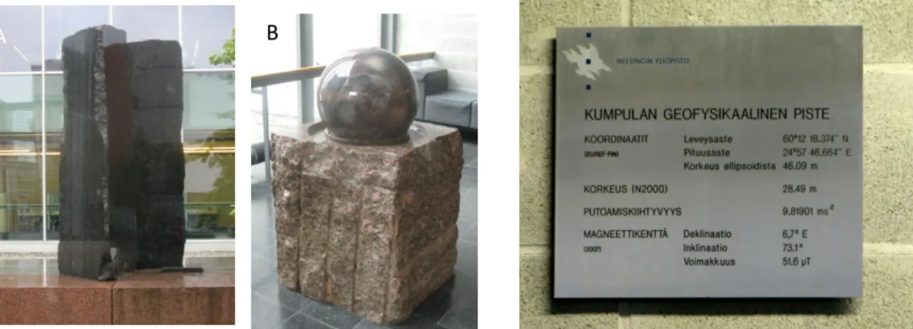
Our Symposium will take place in high-standard lecture hall D101 in the entrance level of Physicum building (Fig. 10B, C). Although not part of the Excursion programme we suggest you to visit three highlights of this building as outlined in Fig 11.
Geology of Helsinki
Helsinki area belongs to the Paleoproterozoic Svecofennian Uusimaa schist belt where schists and gneisses are accompanied by younger granites. The schists and gneisses are partly sedimentary and partly volcanic in origin. The rocks are dated at ~1.9 - 1.8 Ga. The main igneous rocks are granites: mafic intrusives such as diorites or gabbros, are scarce. Several fracture zones cut through the rocks of Helsinki and the most significant ones are aligned to north-northeast such as the famous Kluuvi-fracture in central Helsinki.
Famous people of Helsinki
References
City of Helsinki: www.visithelsinki.fi/juuri-nyt/tapahtumia/helsinki-200-vuotta-paakaupunkina-2012 Artturi Ilmari (A. I.)
Virtanen, a chemistry nobelist (1945), lived and worked 1895-1973 in Helsinki.
Jörn Donner, a writer and movie director, born in 1933.
Tove Jansson (1914-2001), a writer and artist who created the Moomin characters, lived in Helsinki.
Figure 11. Highlights of Physicum building. (A) Rock momument in front of the building, (B) rotating (granite) sphere and (C) geophysical data and co-ordinates in a sign plate on the wall.
23
24
IV Day 1 (Sept. 22, 2012)
IV.1. Keurusselkä impact structure
Lauri J. Pesonen, Selen Raiskila,
Satu Mertanen and Robert Klein
25
IV.1. Keurusselkä impact structure
Lauri J. Pesonen, Selen Raiskila, Satu Mertanen and Robert Klein
After driving from Helsinki, with a short coffee break in Orijärvi, we will arrive in Keurusselkä. The bus will be parked at the Valkeeniemi farmhouse yard (Fig. 12) from where we have about 25 minutes walk to Jylhänniemi, SW Lake Keururusselkä. At the shore of the lake we’ll see well preserved shatter cones at the outcrops (Stop 1, Fig. 14, 16) and on boulders. After walking back, we’ll have lunch, kindly served by City of Keuruu and, the host and hostess (the Valkeeniemi family) of the house. Then we’ll continue our trip to the Keuruu dykes (IV.2).
Figure 12. (A) The Valkeeniemi farmhouse at lake shore of Keurusselkä. (B) Inside of the farmhouse. Photos: Satu Mertanen, 2012.
The Keurusselkä impact structure
The Keurusselkä impact structure, found in 2004 (Hietala and Moilanen, 2004), is among the latest (11th) in Fennoscandia (Fig. 13, Dypvik et al., 2008). The impact origin for Keurusselkä was confirmed with a petrographic investigation of shatter cones (Ferrière et al., 2010). The shock metamorphic planar deformation features (PDFs) found in quartz indicated shock pressures from 2 GPa to 20 GPa (Fig. 26). The structure is located about 30 km west from the small Karikkoselkä impact structure (~230 Ma) and 120 km SE from the ~73 Ma Lappajärvi impact structure (see p.80) within the Central Finland Granitoid Complex (CFGC). The CFGC was formed 1890–1860 Ma ago during the peak phase of the orogeny, where the growing Svecofennian island arc system accreted against the Archaean continent (Nironen, 2005). The granitoids are predominant rocks in the CFGC together with schists and gneisses which are mainly exposed close to the shoreline of Lake Keurusselkä.
According to Kähkönen (2005), the Svecofennian granitic bedrock resulted from remelting of 2100 Ma crust of several microcontinents. Based on εNd of the Tampere schist belt, southern
parts of CFGC, includes an Archaean component as well as abundant approximately 2.0 Ga detritus from the suggested microcontinents.
26
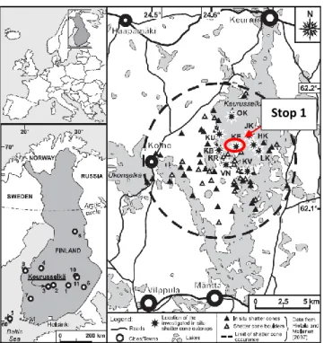
Figure 13. Left: General map of Finland (inset shows its position in Europe) with location of the Keurusselkä impact structure, as well as the position of the 10 other confirmed impact structures from Finland. Right: Detailed geographical map of the Keurusselkä structure, including roads, nearby cities and towns, lakes, sample locations of the investigated in situ
shatter samples (marked with stars), and the occurrence of shatter cone boulders, as reported in Hietala and Moilanen (2004). The 11 confirmed impact structures from Finland are listed in p.80. S. Stop 1 (site KE) consists of in-situ shatter cones.
Supracrustal rocks of Svecofennian domain are, in many cases, separated by faults, fractures and intrusions dividing them into minor belts. The subseguent indicators, in additions to shatter cones and their PDF’s, that support the impact origin was a discovery of a thin pseudotachylitic breccia vein showing planar formations (PFs) in quartz. (Schmieder et al., 2009)
Ages
According to database of Geological Survey of Finland (GSF), U-Pb (zircon) ages of the granitoids in the region show crystallization age of 1883 Ma (Keuruu granodiorite), 1882 Ma (Karikkoselkä granite), 1880 Ma (Multia granite; northern part of the Keurusselkä) and 1876±12 Ma (Keuruu dyke). Volcanic rocks in CFGC are somewhat older, approximately 1900 Ma. The Keurusselkä target rocks show also significant alteration of minerals due to possibly impact related or post impact processes. Three major shear zones cross the area, which are probably originally related to late Svecofennian events (Nironen 2003), but, at least, the NW-SE fracture appears to be cut by the impact structure. This fracture is clearly recognized as a weakly magnetic lineament in the aeromagnetic map (Fig.19).
Indications of impact: shatter cones
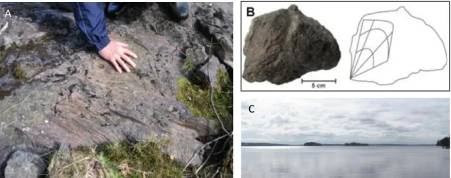
In general, the allochthonous breccia lens with fractured and shocked rocks is the main macroscopic feature present in impact craters (Melosh 1989). In the Keurusselkä area, the bedrock is strongly fractured, including radial fracturing in outcrops which can be distinguished from more linear, old fracture directions (Nironen, 2003) and from the common NW-SE pointing linear Holocene glacial striations detected across Finland (Fig. 14A).
Excursion stop Stop 1
27
Figure 14. (A) Glacial striations and their direction in bedrock shown by Martti Lehtinen, (B) shatter cone boulder and a line-drawing of downward pointing apex. (C) Photographic image across the lake Keurusselkä.
The locations of clearly recognizable in situ shatter cones show in Fig. 16. The cones are abundant and well developed, principally in the northeastern part of the impact structure. Shatter cones are best exposed as clusters in dense and fine-grained metavolcanic rocks, but they are also observed in granites and in mica gneisses (Figs. 14, 15). At the Jylhänniemi peninsula (site KE; Fig. 13, 14, Stop 1), the target metavolcanites are highly fractured and shatter cones occur as large swarms with several different orientations. Shatter cones are generally poorly developed in coarse and weathered granite; in some cases, it is difficult to recognize them as they do not show clear cone apices and, thus, could be misidentified as slickensides.
Fig. 16 shows the sites of Ferrière et al. (2010) with clear in situ shatter cones. Boulders of shatter cones were found in several locations near the in situ ones like at site KE (Stop 1, Fig. 15). In situ shatter cones are mainly 15 cm long and 5–10 cm wide displaying pointing apices (Fig. 15). The cones are well developed, although they occasionally appear only as conical, striated surfaces.
The shatter cones are exposed in an area of diameter of 5 km and considered to represent the central uplift (CU) of the structure as they appear in a circular area close to the presumed center point of the impact (Ferrière et al. 2010). Figure 16b demonstrates that a majority of shatter cones are pointing upward, and have a tendency to point away from the central uplift area. The steep upward direction and the lack of well-defined intersection point of the apices may suggest that the shatter cones are peripherally located, around the central uplift. The planar deformation features in quartz, found from shatter cones in the central uplift, are decorated with fluid inclusions indicating that alteration by post-impact processes was present (Fig. 18).
A
28
Figure 15. (A) Damaged metavolcanic rocks with shatter cones on the shoreline of the Keurusselkä structure (site KE, Jylhänniemi, Stop 1; coordinates N62°9’9.3”, E24°39’4”). (B) Large well developed almost full cone in metavolcanic rock from site KE. (C and D) Lauri Pesonen, Robert Klein and Harri Matikainen on the shore of Lake Keurusselkä, with block samples showing shatter cones.
Figure 16. A) The Keurusselkä sampling sites. Solid ring marks the area of proposed central uplift. Sites with an arrow are sampled outside the map region along a shear zones/faults. B) Geological map showing shatter cone sites and the orientations of their apices and drilling locations (1, 2, 3). Geological map modified after Nironen 2003). C) Shatter cone boulder of metavolcanic rock.
D B A
29
Large impact breccia deposits or impact melt, however, were not found, which further indicates that Keurusselkä is deeply eroded, and possibly much older compared with the other Finnish impact structures (Dypvik et al. 2008).
Shallow drillings in the area of Keurusselkä impact structure: core V-002
Shallow cores (V-001, V-002, V-003) were drilled in the vicinity of the central uplift near Vilppula (Fig. 16b). The core lithologies consist of schists (metagraywackes), metavolcanic rocks, gneisses and breccias. Amphiboles and micas in the breccias are strongly altered and replaced by secondary chlorite. Chloritization may indicate widespread impact-induced hydrothermal alteration of the target rocks or it may be related to regional tectonic shearing.
The most interesting shallow drill core is the V-002 (Fig. 17), since it reveals distinct brecciation.
Figure 17. Petrophysical properties (density D, susceptibility K, NRM and
Q) of Vilppula drill core V-002 with core lithologies. Gray sections within the data indicate the breccia or porfyroblast layers in the analysed cores.
Fig. 17 depicts narrow monomictic breccia veins in V-002 The density (average 2662 kg/m3) has been observed to vary both due to fracturing and differences in lithology but the breccia vein cutting the parautochthonous subcrater floor has a very low density ( ~2576 kgm-3), typical to suevite-breccia found in many impact structures (e.g. Lappajärvi, Karikkoselkä).
Based on topographic and satellite images, the estimate for the original size of the structure is 30 km (Raiskila et al. 2012), which is consistent with a 5 km wide central uplift. Therefore, the Vilppula cores are situated inside the impact region. Despite the location of the cores the samples did not reveal apparent impact features except perhaps the breccia veins (Fig. 17) surrounding target.
Post-impact hydrothermal alteration of crater rocks is a common impact-related phenomenon and this kind of activity is known from over 60 impact structures on Earth (Naumov, 2005). Occurrence of secondary mineral assemblages with ore-forming minerals and chemical alteration combined with fluid inclusions in the planar deformation features in
30
quartz (Ferrière et al., 2010) are typical evidences of hydrothermal alteration on Keurusselkä impact structure. The secondary minerals in Vilppula drill cores are mainly chlorite and pyrite. The first assumption for the origin of the studied Vilppula monomictic breccia veins would be endogenic. However, impact origin is likely due to the fact that these breccias are situated approximately 3 km from the assumed crater center showing impact pressures of 20 GPa. We note here in passing that petrophysical, rock magnetic and petrographic data of Vilppula drill core sample show different behavior of the breccia samples compared to background bedrock samples (see Raiskila et al. 2012). They suggest (but do not prove) a shock influence.
However, pseudotachylitic breccia veins are quite common in geological environments, and they are usually also associated with tectonic events. Yet, the discovery of weak shock features (PFs) in quartz (Schmieder et al. 2009) could point to the impact origin for this pseudotachylitic breccia and suggest a Mesoproterozoic age for the impact event. We return to this point in chapter, “Paleomagnetism”.
Shatter cones and planar deformation features
The shock produced planar deformation features (PDFs) in quartz and feldspar are clear evidence of a hypervelocity impact, as they are distinct from non-impact deformation features (French and Koeberl 2010). PDFs are also critical in recognizing deeply eroded impact structures, such as the Keurusselkä structure lacking other impact lithologies.
Ferrière et al. (2010) have reported results from selected samples (e.g. shatter cone of site KE (our Stop 1) using universal-stage measurement method. These samples revealed clear impact-related shock features, such as PDFs and PF’s in quartz and also feldspar and other mineralogical changes due to the shock. Examination of these thin sections showed that quartz grains with PDFs are mainly granulated. Overall, PDFs were found in a variety of minerals including quartz, plagioclase, and also apatite; specimens from site KE contain weak PDFs in plagioclase with set of PFs and kink bands in biotite grains. Thin-section sample (site KE) showed similar features to those of thin-sections of the Lappajärvi impact rocks (Lehtinen 1976) and the Karikkoselkä borehole samples (Pesonen et al. 1999).
The shatter cone samples from Jylhänniemi site (KE, Stop 1) consist of fine-grained granodiorite, showing slight variations in mineral composition and in grain size, reflecting the inhomogeneous nature of the basement rocks of the Keurusselkä structure, even at a local scale.
31
PDFs occur in quartz grains as narrow, nondecorated or slightly decorated, planes, but more commonly as bands of aligned, tiny fluid inclusions (decorated PDFs), spaced 2–10 μm apart. The PDFs commonly occur as multiple sets per grain, generally two sets (Fig. 18) under the flat-stage optical microscope, and up to three to five sets when seen under the U-stage microscope. The PDFs are generally decorated with tiny fluid inclusions, usually less than 1–2 μm in diameter (in some cases up to 3–4 μm). The decoration of the PDFs in Keurusselkä quartz grains indicates that they were subjected to postshock alteration (such as due to a saturated target or fluid circulation). Detailed description is given in Ferriere et al. (2008).
Figure 18. Histogram of the absolute frequency percent of indexed PDFs in quartz grains from shatter cone samples from the Keurusselkä impact structure, as determined using the new stereographic projection template (NSPT; Ferrière et al. 2009a) for the indexing. Note that PDF planes that fall into the overlap zone between {10Ī4} and {10Ī3} crystallographic orientations are considered as {10Ī3} orientations in this figure, as suggested by Ferrière et al. (2009), but are reported in gray on top of the uniquely indexed {10Ī3} orientations. a) Plot of combined PDF data from thin sections VN3A and VN3B. b) sample VN3B
Shatter cones and crater size
Shatter cones occur usually in the central part of complex impact structures and in a few rare cases, as isolated clasts in impact breccias (e.g., at the Haughton impact structure, Canada). The distribution of shatter cones at a minimum impact site has been used as a parameter for estimating the original size of a structure, particularly for old and eroded impact sites such as at Keurusselkä. It has been previously proposed that when restored to their original position prior the impact, shatter cones apices indicate the point of impact (e.g., Manton 1965). However, shatter cones at the Keurusselkä structure are generally found as clusters (rarely as single specimens) of partial or rarely complete cones, with frequently opposite orientations at the decimeter scale. Thus, the use of shatter cone apex orientation to determine the center of the Keurusselkä structure is likely to yield incorrect results. This is consistent with observations of shatter cone orientations from Vredefort Dome (see Raiskila et al. 2012 and references therein).
32
A minimum crater size can, however, be estimated based on the distribution of in situ shatter cones. These calculations yield to a minimum estimate of the original diameter ≥ 30km. Keeping in mind that we do not know about the amount of erosion in Keurusselkä case.
Geophysics
Aeromagnetic data from the Keurusselkä impact area shows prominent high amplitude magnetic anomalies (Fig. 19B). High-amplitude (up to 500 nT) short wavelength anomalies occur at the ~6 km wide area, which coincides with locations of the in-situ shatter cones and is distinguished from the overall regional field. This circular positive magnetic anomaly coincides with the negative Bouguer anomaly, but does not extend as far to the East. Circular anomalies further away around the central magnetic high-amplitude anomaly are likely of regional origin.
In the Keurusselkä structure, the shatter cones within crystalline rocks are exposed in an area of 19 km2, and show distinctively higher magnetization features on aeromagnetic map (Fig. 19b). This anomaly is interpreted to form the circular central uplift of the structure. On the eastern side of the central anomaly is a circular magnetic low for which we do not yet have a definite explanation. The magnetic pattern in the Keurusselkä area shows also linear and folded schist belts and roundish granitoid intrusions, which are seen as magnetic lows. Raiskila et al. (2011) proposed that results from the drill core samples and the Keurusselkä shatter cones imply magnetic enhancement of the schist belt at the central uplift due to the impact.
The gravity data of the Keurusselkä region show a circular gravity minimum of ~9 m Gal around the central uplift (Fig. 19B). Chain of positive gravity anomalies with a diameter of 25 km is recognized around the central uplift as possible traces of the rim. Gravity influence of the Keurusselkä lake water was reduced from all gravity observations in the area by calculating vertical gravitation of lake mass with 6.4 meter mean depth of Keuruselkä lake area and with standard water density of 1000 kgm-3. Other smaller circular negative Bouguer anomalies in the area were also found.
Figure 19 (A) Aeromagnetic map (courtesy of GTK). Shatter cones are marked as crosses. (B) Local Bouguer gravity map (courtesy of FGI).
33
These circular shaped anomalies are, however, mainly caused by younger granitic intrusions (~1860 Ma), which are recognized also in the geological map by Nironen (2003) and in aeromagnetic map as low amplitude regions (Fig. 19A).
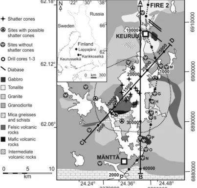
The FIRE2 seismics profile (Kukkonen and Laitinen 2006)crosses eastern margin of the Keurusselkä structure from NS direction (Fig. 20).Recently, a tomographicanalysis of the seismic data was done to study the possible impact features (Institute ofSeismology, University of Helsinki, unpublished data). The tomographysic velocity model of FIRE 2 did not show anyclear boundaries that could be tied with the Keurusselkä structure, however, within thestructure area somewhat slower seismic velocities were recognized from the depth range of 570meters.
Figure 20. Dotted line shows the FIRE 2 seismic profile. The geological setting is by Nironen (2003) and the two marked modeling profiles (A-B and C-D) are shown as solid lines.
Crater dimensions from geophysics
To estimate the dimensions of the crater structure, scaling laws and dimensions outlined in
Fig. 21 were applied. A medium size impact crater (with rim-to-rim diameter D ≈ 4–50 km) is of complex type with a central uplift (CU) (Fig. 21A). Assuming the shatter cones are located within the eroded CU of Keurusselkä structure, and based on the approximate diameter of
their coverage area (DCU ≈ 6 km), original diameter would be between 16-23 km. The
structural uplift would be from 1.5 to 2.2 km and the diameter of transient cavity DTC from 11
to 21 km (see Raiskila et al. 2012 and references therein). To adapt these theoretical parameters to the Keurusselkä structure and its central uplift, would results with a minimum crater diameter of 16 km, although the diameter of central uplift increases with the erosion.
34
Since the central peak collapse may start when the crater diameter exceeds 24 km (Abels 2003), it would suggest that the central uplift of Keurusselkä is not collapsed.
A digital elevation model (DEM) over Keurusselkä region (Fig. 21B) shows elevation points, which define a ring of hills, with anomalous heights over regional average, which could point the crater rim. The possible rim is partly missing as gaps along the ring, especially in southwest.
Figure 21. (A) Crosscut of a typical complex impact crater with central uplift (modified from Abels, 2003). Unevenly eroded erosion level suggested for Keurusselkä structure is marked with dashed line. (B) Elevation points (black arrows) on DEM map indicate the place of the suggested crater rim and the rim-to-rim diameter.
Modelling methods
A straightforward two-dimensional magnetic and gravity model is introduced to interpret the observed geophysical anomalies. Based on the models an estimate of the dimensions (diameter, depth) of Keurusselkä impact structure can be made.
The joint (gravity, magnetics) modeling was carried out using a 2.5-dimensional cross-sections with modelled source bodies of target rocks and impact generated anomalous sources. Details are presented in Raiskila et al. (2012) including petrophysical contrasts (model vs. background). The 2.5-dimensional models describing of a 5-km-deep section of the upper crust, are shown in Fig. 22. All the geological bodies in the model are related to the known geological features. The striped area represents a bowl shaped depression of gravity minimum with density of 2500 kgm-3 as partly based on Vippula drill core studies. This area shows the crushed and damaged crater basement, which exceeds to the depth of ~2 km.
They suggested that the strain model, where stresses, strains, and strain rates are all highest near the impact site and decrease with radial distance, should correlate with observed variations in bulk density (see also Pesonen, 2012). However, potential field
35
anomalies strongly depend on the erosion level and the deformation degree of the impact structures (Plado et al., 1999).
Figure 22. The line drawing interpretation of the FIRE2 seismic profile Nironen et al. (2006) Darker grey area represents the gneissose schists (see Fig. 24) and combined gravity and aeromagnetic models of a SW-NE (A to B) and NS (C to D) sections over Keurusselkä impact structure. Vertical dashed line in both models marks the cutting point of the profiles.
The NS profile (A-B) along the FIRE 2 seismic profile highlights the eastern margin of the circular central magnetic anomaly. The numbered source bodies from 1 to 5 have petrophysical values of (1= tonalitic) k=2900×10-6 SI, D=2720 kgm-3, (2=granitic) k=1000×10
-6 SI, D=2700 kgm-3, (3=metavolcanic rock) k=3000×10-6
SI, D=2650 kgm-3, (4=sill/granitic) k=1000×10-6 SI, D=2760 kgm-3 and (5=mica gneiss/schist) k=2000×10-6 SI, D=2900 kgm-3. The darker gray objects (positions 11000 and 32000) are gabbro intrusions and the black rod feature (position 10000) indicates possible the continuation of the Keuruu diabase dykes or a gabbro intrusion.
Keurusselkä is deeply eroded: the rim and the impact rock units have been removed almost completely and only the upper part of the fractured basement is exposed. Yet, weak morphological features can be seen around the central uplift, which are partly asymmetric (Fig. 22). Reasons for uneven erosion could be an oblique impact, geological anisotropy, or both. The consistent bowl shaped region, down to the depth of 3 km, in Keurusselkä area can be identified from the seismic profile data (Nironen et al., 2006; Fig. 22.). Our model (NS-profile) highlights this area of less dense and fractured bedrock. This area has a diameter of 30 km and it explains the observed circular 6 mGal negative local Bouguer anomaly (Fig. 22).
Contrast to the Lappajärvi impact structure (diameter ~23 km, age 73 Ma), which has -11 mGal gravity anomaly, Keurusselkä could represent a ~0.5–1 km deeper section of the bedrock than Lappajärvi, based on the erosion estimation introduced by Plado et al. (1999). Heterogeneity of the target could also be the reason for the reduced anomalies. Also subsequent geologic processes are able to weaken the negative gravity anomaly, such as postimpact thermal alteration.
The measured magnetic anomalies of the Keurusselkä impact structure are complex. Impact-induced changes in the aeromagnetic anomaly pattern have typical impact features
36
of a strong circular anomaly in the center of the structure and an annular magnetic “halo” around the center (Pesonen et al., 2002), which is irregular due to geological heterogeneities and partly missing in the west side of the Keurusselkä structure. The positive central magnetic anomalies are clearly related to the area with in-situ shatter cones, where the rocks differ from un-shocked target rocks having increased magnetizations. The high-amplitude magnetic anomalies in the aeromagnetic data are associated with the outer margin of the central uplift (Fig. 22; A-B profile). Few gabbro intrusions create also sharp anomalies, while negative magnetic anomalies are linked to the granitic intrusions. The SW-NE trending profile highlights a polygonal shape body of a strongly magnetized area, revealing a circular central uplift with a peak anomaly in its center (Fig. 23).
Figure 23. A 3D-image of aeromagnetic map. Ring area marks the magnetic anomaly associated to the central uplift. (Raiskila et al. 2012)
Paleomagnetic results
Paleomagnetic techniques and results are summarized in Raiskila et al. (2012) as based on alternating field (AF) and thermal treatments. Due to weak intensities and often also unstable demagnetization behavior, only less than half of the selected and demagnetized specimens showed stable remanence directions.
As the studied samples present the deeply eroded impact crater basement, we were not able to use paleomagnetic field tests for verifying the primary nature of isolated remanent magnetization directions. We attempted to apply the impact test of Pesonen (2001) in seeking evidence of decay of shock as a function of distance but the results were inconclusive. Four new remanece components (A, B, C and E) were isolated in Keurusselkä rocks. The directions are summarized in Fig. 24.
Component A. This component is best preserved on sites KL and KM ~10-20 km away from the impact center. It is especially observed during the thermal demagnetization but is also isolated during the AF treatments. This “A” direction is also clearly shown on sites, which are close to the faults and fractures.
37
The mean A direction is a typical Svecofennian direction (D~335º, I~46°) (Fig. 24, 25), observed in numerous locations within the Svecofennian terrain in Finland and Sweden (Pesonen et al.1991). Moreover, it is strikingly similar to direction isolated from unshocked granites near the nearby Karikkoselkä impact structure (Pesonen et al. 1999).
Figure 24. Site mean paleomagnetic directions for target rock and shatter cones. Component A refers to characteristic Svecofennian direction. Components B, C, and E denote the secondary directions. Black symbols display site means withα95 confidences about the means
and gray symbols overall mean directions. Present Earth Field direction is marked as black X.
Component B. The NW upward intermediate inclination component B is isolated for nine sites occasionally occurring in the same samples with component A. It is best preserved in the sites with shatter cones showing mostly stable magnetizations and low-to-intermediate coercivities during the AF treatment. Blocking temperature ranges between 150 °C and 580 °C. B is in most cases isolated in the shatter cones the central uplift area with impact pressures around 20 GPa.
The mean direction of component B (D~42°, I~64°) is distinct from PEF (D~7º, I~73º) and yields a pole for impact-affected basement samples and shatter cones (Fig. 25).
The other components occasionally observed (C, E) are discussed in Raiskila et al. (2012).
Discussion
Petrophysical properties
Petrophysical properties of the Keurusselkä impact structure are generally typical for the granitic bedrock (CFGC). However, shocked crystalline rocks with shatter cones within the central parts of the structure show enhanced magnetic susceptibilities, which are interpreted to be associated with the central uplift. Increased susceptibilities in Keurusselkä structure could be a result of modification of magnetic carriers due to high P-T-conditions during the impact and later in hydrothermal processes. Hydrothermal activity has been significant after the impact event and it has caused fluid inclusion trails decorating the originally amorphous planar deformation features (PDFs) in quartz (Ferrière et al. 2010). Linear and folded schist
38
belts dominate the overall magnetic pattern over Keurusselkä. The magnetic signal of pyrrhotite-bearing schist belts is possibly also enhanced due to the impact (Raiskila et al. 2011).
Target rocks in impact craters are subjected to extreme pressure (up to 100 GPa) and temperature (up to 1000 °C) during the impact event. Typically, the porosity and fracture density decay gradually from the center of the crater to outer regions of the impact structure (Cockell et al. 2005). In the Keurusselkä area, the average porosities of shatter cones are low because of the weakly shocked crater basement and lack of highly porous impact rocks, such as suevites and impact melt breccias. The degree of fracturing is associated distinctively with the appearance of shatter cones at the central uplift area, and it is in resemblance to fracturing of the Karikkoselkä impact structure formed on the same granitic target rock (Pesonen et al. 1999).
Paleomagnetic Ploes and APWP
The characteristic component A obtained for different lithologies of unshocked target rocks and occasionally from shatter cones shows the typical Svecofennian remanent magnetization direction. This component is interpreted to represent the primary magnetization acquired during the formation and slow cooling of the CFGC at 1880– 1860 Ma (Fig. 25A). Field tests for the CFGC area, to confirm the primary nature of magnetization, are not possible except in the case of nearby Keuruu dykes (~1876 Ma), with positive contact test. The magnetization direction “A” has been widely observed throughout the Fennoscandian Shield including the unshocked granitic target rock (1880 Ma) from Karikkoselkä impact structure.
Figure 25. A) Mean paleomagnetic poles for characteristic Svecofennian component A and secondary component B calculated from shatter cone sites and unshocked target rock sites. Baltica “key poles” and chosen well-dated poles are marked as crosses with A95circles (Buchan et al. 2000; Salminen et al. 2009). B)
Fennoscandian Phanerozoic APW path (Torsvik et al. 1996; Smethurst et al. 1998; Torsvik and Rehnström 2001, 2003) and mean paleomagnetic poles for the south pole of component B and secondary components C and E.
39
Pole B is obtained mainly from shatter cones. This pole does not agree with the Precambrian key poles of Baltica (Elming et al. 1993). However, it is close to the pole of a well-dated (1122 ± 7 Ma) Salla diabase dyke (Salminen et al. 2009), indicating late Mesoproterozoic magnetization age. This agrees with the U-Pb age of 1140 ± 6 Ma of the pseudotachylitic breccia vein (Schmieder et al. 2009), supporting the idea that component B represents the magnetization due to the impact event. Component B has also low coercivity, which could be an indication of shock remanent magnetization (Halls 1979). Keurusselkä and Salla poles are far from the Precambrian APWP of Baltica, thus creating a large clockwise loop from 1265 Ma to 1036 Ma, Salla pole (1122 Ma) being the apex of the loop. Salminen et al. (2009) discussed the similarities between the pre-Sveconorwegian (approximately 1.3–1.0 Ga) APWP loops of Baltica, Laurentia (including Logan Loop), and Kalahari-Grunehogna. These cratons seem to reach their apexes at slightly different times. Salminen et al. (2009) proposed that Baltica and Laurentia drifted together until 1.12 Ga and later separated at 1.04 Ga. If indeed all continents will reveal the 1.15-1.05 Ga “loop” a possibility of Mesoproterozoic true polar wander event (Evans 2003) will arise. However, better dated paleomagnetic poles for this interval are required to test this idea. Nevertheless, the ~1.12 Ga poles Finland provide hints that the Mesoproterozoic Baltica–Laurentia unity in the Columbia supercontinent may have lasted until 1.12 Ga.
The opposite polarity of Keurusselkä pole B fits also to the Phanerozoic APW path (230 Ma). Mertanen and Pesonen (1995), Mertanen et al. (2008), and Preeden et al. (2009) have presented similar paleopoles (265 Ma) obtained from South Finland shear zones. They favored Phanerozoic age for their “B”-paleopole and interpreted them as remagnetizations caused by oxidizing fluids.
Conclusions
The Keurusselkä structure is a deeply eroded complex crater lacking the impact melt and rock lithologies, such as suevite and breccia. Impact features include (i) shatter cones in crystalline basement rocks with distinct planar deformation features (PDFs) in quartz, heavily fractured basement, (iii) discoveries of breccia veins in drillcores and a pseudotachylite with “young” age of ~1.14 Ga.
Petrophysical and rock magnetic properties imply that increased magnetization within the area, where shatter cones were observed, represent the central uplift with diameter of 5– 10 km. Alteration of minerals in hydrothermal processes in the crater basement could be the reason for increased magnetic properties.
40
Four paleomagnetic components for the Keurusselkä rocks are interpreted to record the regional Mesoproterozoic and possible Paleozoic geological events during the evolution of the Fennoscandian Shield. Notably, component B is isolated in crater basement and shatter cones and is interpreted to represent magnetization related to the impact event at ~1.12 Ga supported by the 40Ar/39Ar age of the pseudotachylite vein (1140 ± 6 Ma). This new pole from the Keurusselkä impact structure gives further support for the proposed large APWP loop of Baltica during 1.26-1.12 Ga.
41
IV Day 1 (Sept. 22, 2012)
IV.Ib.
Paleomagnetism and petrophysics of the Keuruu dykes
Lauri J. Pesonen, Robert Klein,Selen Raiskila,
Satu Mertanen and Pathamawan Sangchan
42
IV.Ib. Paleomagnetism and petrophysics of the Keuruu dykes
Lauri J. Pesonen, Robert Klein, Selen Raiskila, Satu Mertanen and Pathamawan Sangchan
The Keuruu diabase dyke swarm in Central Finland forms the second target of the excursion and comprises Stops 2 and 3. The dykes are of Paleoproterozoic age (~1876 Ma) and cut the Svecofennian gneisses, granodiorites and gabbros. The nearly vertical dykes strike NNW-SSE, have maximum length of a few kilometers and widths of ~ 0.3-2 m. More than one hundred samples were collected from 17 dykes in order to constrain the Paleo- to Mesoproterozoic APW-path of Fennoscandia, to estimate the ancient latitude of Fennoscandia at the time of Svecofennian orogeny and to study the magnetic fabric of the dykes and its relation to the Natural Remanent Magnetization (NRM). Chemical composition and petrophysical properties of the dykes are also presented in addition to a few paleointensity determinations.
Multicomponent analysis of NRM’s, reveal three components: (i) a primary magnetization of dual polarity (N and R), (ii) a secondary component (B) and (iii) a viscous PEF-overprint. Positive baked contact test strongly suggest that the acquisition time of primary magnetization is close to the time of dyke emplacements during or slightly after the peak of the Svecofennian orogeny. The origin and nature of the secondary component is unclear but its connection to the Keurusselkä impact event at ~1120 Ma is not ruled out.
The schematic view of the Paleoproterozoic Keuruu dyke swarm is outlined in Fig. 26. where the NNW-SSE trending Keuruu dykes appear as an “isolated“ swarm within Central Finland Granitoid Complex (CFGC). It is possible that Keuruu dykes show fanning to SSE. However, they are not an offshoot of the variable trending undated Kuru-Orivesi dykes, nor of the WNW-ESE trending Häme or Suomenniemi dyke swarms of late Paleoproterozoic age (~1.66 Ga). The latter ones show distinct fanning to ESE and seem to merge with the Wiborg or Suomenniemi rapakivi massifs.
Figure 26. A) Dyke map of Southern Finland (modified after Rämö 2005). B) Map of the Keuruu diabase dykes in cenral-west Finland. (a) Location of the Keuruu area, (b) bedrock geology including diabase dykes (Stop 2, 3), (c) main dyke exposure in a railway cutting (Stop 2). Legend: 1. diabase dyke, 2. granodiorites, 3. diorite, 4. gabbro, 5. railway track. Dyke widths and lengths not to scale (after Puranen et al. 1992).
A
43
Fig. 26b outlines the Keuruu dyke swarm in more detail. Three distinct clusters are visible: (i) Keuruu railroad cluster (Stop 2), (ii) Pirttivuori cluster (dated dyke) and Multia cluster (Stop 3).
Age of Keuruu dykes
O. Kouvo (GTK) made several attemps in trying to date the Keuruu diabases using U-Pb techniques applied to zircon and other minerals. In spite of these attempts (only few zircon grains isloted with sufficient amount of U) no reliable age estimate was found. The 207
Pb-206Pb age of slightly discordant U-Pb analysis on zircon of the Pirttijärvi dyke (N polarity)
yield an age of 1876±9 Ma, which can be regarded as the best estimate for the age of Keuruu N-polarity dykes. This age is consistent with field observations showing that the dykes cut both the Keuruu gabbro and granodiorite (1883±14 Ma) (Fig.39b). No age data are available for the R-polarity dykes.
Petrophysics
Figure 27 summarizes the petrophysical data of Keuruu diabase dykes in two plots: density vs. susceptibility (A) and NRM vs. susceptibility (B). Petrophysical data are shown according to their paleomagnetic polarity (N, R or M (=mixed)) since most likely the polarities represent two separate pulses of dyking (see also geochemistry and paleomagnetism).
Fig 27. Summary of petrophysical properties of selected specimens from Keuruu diabases, baked and unbaked granodiorites and gabbro. N(R) denotes normal (reversed) magnetic polarity and M cases where they are superimposed. (A) susceptibility vs. density, (B) NRM vs susceptibility.
From Figure 27 we observe that:
1. Densities of diabases vary from ~2870 to ~2950 kgm-3 being typical or slightly lower than in mafic dykes in Finland as a whole (GTK database).
44
Figure 29. (a) Depencence between magnetic lineation L and factor F for dyke groups. The area defined by dashes in the lower left corner characterizes the typical field of magnetic flow fabrics. (b) Anisotropy directions which was the basis for dividing the dykes into h, v, and m groups. See Puranen et al. (1992) 2. There is a tendency that the density of N-polarity dykes is slightly higher than that in R dykes. There are also slight differences in chemical and mineralogical compositions between the two polarity groups.
3. Susceptibility and its anisotropy do not show any trend with respect to polarity.
4. Unbaked granodiorites, as expected, have much lower densities (more Si) than mafic dykes. The baked granodiorites have “enhanced” densities, susceptibilities, NRM’s and Q-values presumably due to baking. These samples were selected to paleointensity determinations.
5. There is no trend in Q-values with respect to polarity: Q varies from 0.6 to ~4.5, typical for mafic dykes.
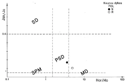
Hysteresis results are summarized in the Day-plot (Fig. 28) and suggest that the remanence carriers are in the borderline of the PSD-MD grain size consistent with AF-demagnetization behavior (Figs. 34-36).
Figure 28. Hysteresis data of Keuruu dykes plotted in the standard Day-plot. (Day et al., 1997)
Magnetic fabric
A detailed review of the magnetic fabric of Keuruu dykes was carried out by Puranen et al. (1992) using the method by Lister and Kerr (1991). The dykes, as based on magnetic fabric can be devided into three groups: (i) group h with horizontal, (ii) group v with vertical, and (iii) group m with intermediate magma flow fabric. The anisotropy data of Keuruu dykes are plotted in Fig. 29 as L vs. F-plots.
b a
45
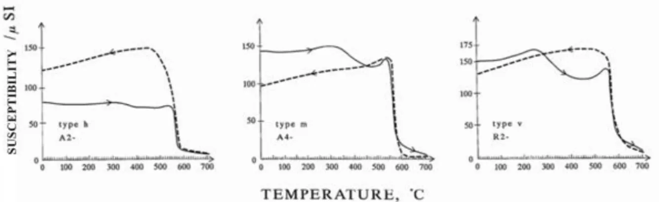
Magnetic mineralogy, the Curie-point determinations (Fiof Keuruu diabase samples with h, v or m fabric types reveal the following characteristics:
1. All fabric types show thermal hysteresis: the heating and cooling curves differ indicating chemical alterations during heating.
2. Although several phases are seen in the heating curves: e.g., one at ~320-360°C (pyrrhotite?), all of them show Tc’s near 570°C indicating Ti-poor magnetite as the main carrier. This is supported by distinct Hopkinson-effects at ~530-560°C in all fabric types.
3. Weak evidences for hematite is present consistent with microscope observations.Figure XX. Three examples of thermomagnetic curves (susceptibility vs. temperature) of Keuruu diabases. Left: fabric type h; Middle: type m and Right: type v.
Figure 30. Three examples of thermomagnetic curves of Keuruu dyke samples with h, m and v fabric types.
Petrography and geochemistry
Microscopic studies of the Keuruu diabases reveal that the predominant ferromagnetic mineral is titanomagnetite, which is rather evenly distributed within the matrix as separate grains with sizes typically in the PSD-MD range 20-200 μm (see Puranen et al. 1992 for details).
Stop 2. This “railway exposure (Fig. 31) stop comprises several distrinct diabase dykes cutting the Keuruu granodiorite (Fig. 31) as well as the Keuruu gabbro. In the former case we can observe several cutting dykes (width from 30 cm to 1 m), sharp contacts with chilled margins and also dyke offshoots or apophyses (Fig. 31b).
The lack of secondary mineral inclusions in the titanomagnetite grains and their euhedral shape indicate that they are of primary origin, although some of the larger magnetic grains are partially martitized. Secondary magnetite is also commonly present as chains of platy grains that fill microcracks, and as dustlike concentrations of almost submicroscopic particles produced during the alteration of mafic minerals. The secondary alteration may be deuteric (late crystallization) but it can also be post emplacement alteration. Candidates for the latter one are late Svecofennian tectonic events (1.78-1.7 Ga) or, as pointed out in the previous
46
Chapter, the Mesoproterozoic impact induced hydrothermal event at ca. ~1.12 Ga. The paleomagnetic data give further support for this latter possibility.
The coarser central parts of the wider Keuruu dykes are ophitic and finer marginal parts are often porphyritic in texture. The ophitic parts are mainly composed of weakly aligned plagioclase laths (An50-55) and hornblende grains. The porphyritic parts contain sporadic
phenocrysts of plagioclase and pyroxenes (hypersthene and augite). In addition to these minerals, the matrix commonly includes small amounts of biotite, chlorite, apatite, epidote, titanite and pyrite (Marmo and Mikkola, 1963). The dated Pirttivuori dyke (1876±9 Ma) belongs to this type. The overall mineral composition and the degree of alteration do not change systematically between the different dyke groups and dyke widths.
The chemical composition of the Keuruu diabase is summarized in four discrimination diagrams (see data in Puranen et al. 1992). The results indicate that the basaltic magma was not intruded directly from the mantle but has undergone extensive near surface (low pressure) fractionation. C A A A B B
Figure 31. (A) and (B) Vertical dykes (widths 80 cm and 30 cm) with distinct contacts and chilled margins cutting Svecofennian grano-diorite; Railway exposure (Stop 2). (C) Off shooting dykelet (width 10 cm); Railway exposure on the side of the railway where the bus stops. Photos by Satu Mertanen.
47
The diabase dykes are tholeiitic in character and were intruded in a continental setting. The dyke groups with different magnetic fabrics (h, v, m) are chemically quite similar, their degree of alteration is low, and they bear a close chemical resemblance to the coarse-grained gabbro of Keuruu. On the other hand, the overall mineral composition and the chemical composition of these dyke groups are not significantly different, suggesting a common or similar magm