___________________
___________________
___________________
___________________
___________________
___________________
SIMATIC
PROFIBUS
PROFIBUS with STEP 7 V12
Function Manual
Documentation guide
1
Description
2
Parameter
assignment/addressing
3
Diagnostics
4
Functions
5
This manual contains notices you have to observe in order to ensure your personal safety, as well as to prevent damage to property. The notices referring to your personal safety are highlighted in the manual by a safety alert symbol, notices referring only to property damage have no safety alert symbol. These notices shown below are graded according to the degree of danger.
DANGER
indicates that death or severe personal injury will result if proper precautions are not taken. WARNING
indicates that death or severe personal injury may result if proper precautions are not taken. CAUTION
indicates that minor personal injury can result if proper precautions are not taken. NOTICE
indicates that property damage can result if proper precautions are not taken.
If more than one degree of danger is present, the warning notice representing the highest degree of danger will be used. A notice warning of injury to persons with a safety alert symbol may also include a warning relating to property damage.
Qualified Personnel
The product/system described in this documentation may be operated only by personnel qualified for the specific task in accordance with the relevant documentation, in particular its warning notices and safety instructions. Qualified personnel are those who, based on their training and experience, are capable of identifying risks and avoiding potential hazards when working with these products/systems.
Proper use of Siemens products
Note the following: WARNING
Siemens products may only be used for the applications described in the catalog and in the relevant technical documentation. If products and components from other manufacturers are used, these must be recommended or approved by Siemens. Proper transport, storage, installation, assembly, commissioning, operation and maintenance are required to ensure that the products operate safely and without any problems. The permissible ambient conditions must be complied with. The information in the relevant documentation must be observed.
Trademarks
All names identified by ® are registered trademarks of Siemens AG. The remaining trademarks in this publication may be trademarks whose use by third parties for their own purposes could violate the rights of the owner.
Disclaimer of Liability
We have reviewed the contents of this publication to ensure consistency with the hardware and software described. Since variance cannot be precluded entirely, we cannot guarantee full consistency. However, the information in this publication is reviewed regularly and any necessary corrections are included in subsequent editions.
Preface
Purpose of the manual
This function manual provides an overview of the PROFIBUS communication in combination with SIMATIC STEP 7 V12.
STEP 7 V12 is integrated into the powerful graphic Totally Integrated Automation Portal (TIA Portal), the new integration platform for all automation software tools.
This function manual supports you in planning a PROFIBUS system. The manual is structured into the following subject areas:
● PROFIBUS basics ● PROFIBUS diagnostics ● PROFIBUS functions
Basic knowledge required
The following knowledge is required in order to understand the manual: ● General knowledge of automation technology
● Knowledge of the industrial automation system SIMATIC ● Knowledge about the use of Windows-based computers ● Proficiency with STEP 7
Scope
This function manual is the basic documentation for all SIMATIC products from the PROFIBUS environment. The product documentation is based on this documentation. The examples are based on the functionality of the S7-1500 automation system.
Conventions
STEP 7: In this documentation we use "STEP 7" to refer to the configuration and programming software as synonym for "STEP 7 V12 (TIA Portal)" and later versions. This documentation contains figures of the devices described. The figures may differ slightly from the devices supplied.
Additional support
Information on the offers of our Technical Support are available in the appendix Service & Support (Page 79).
The technical documentation for the individual SIMATIC products and systems is
available on the Internet ().
The online catalog and the online ordering system are available on the Internet
Table of contents
Preface ... 3 1 Documentation guide... 7 2 Description... 9 2.1 Introduction to PROFIBUS...9 2.1.1 Applications of PROFIBUS DP ...9 2.1.2 PROFIBUS terminology ...11 2.1.3 PROFIBUS DP interface...152.2 Structure of PROFIBUS networks...16
2.2.1 Passive network components for RS 485 networks ...18
2.2.1.1 RS 485 cables...18
2.2.1.2 PROFIBUS FastConnect system...19
2.2.1.3 PROFIBUS bus connector...21
2.2.1.4 M12 bus connector ...23
2.2.1.5 Bus terminals for RS 485 networks ...23
2.2.1.6 M12 bus terminating resistor...23
2.2.2 Passive components for optical networks...24
2.2.2.1 Fiber-optic cables...24
2.2.2.2 Plastic and PCF fiber-optic cables...25
2.2.2.3 Glass fiber-optic cables...26
2.2.3 Active network components...28
2.2.3.1 Network components in electrical networks...28
2.2.3.2 Network components in optical networks ...32
2.2.4 Examples for topology ...34
2.2.4.1 Topology with RS485 repeater ...34
2.2.4.2 Topology with diagnostic repeater ...36
2.2.4.3 OLM topology...39
2.2.4.4 WLAN topology ...39
2.2.4.5 Connecting PROFIBUS to PROFINET ...40
3 Parameter assignment/addressing ... 41
3.1 Assigning the DP slave to a DP master...42
3.2 PROFIBUS address...44
3.3 Network settings ...45
3.4 Cable configuration ...48
4 Diagnostics ... 57
4.1 Overview ... 57
4.2 Diagnostics using the display of the S7-1500... 58
4.3 Diagnostics with the diagnostic repeater ... 59
4.4 I&M data (Identification and Maintenance) ... 60
5 Functions ... 61
5.1 Isochronous mode... 61
5.1.1 What is isochronous mode?... 61
5.1.2 Use of isochronous mode ... 62
5.1.3 Isochronous applications... 62
5.1.4 Sequence of synchronization... 64
5.1.5 Requirements for configuration... 65
5.1.6 Configuring isochronous mode ... 66
5.1.7 Diagnostics and interrupt functions... 69
5.1.8 Parameter settings for isochronous mode ... 70
5.1.8.1 Viewing isochronous mode parameters... 71
5.1.8.2 Change parameters ... 72
5.2 Acyclical data exchange... 74
5.3 SYNC/FREEZE groups... 75
5.4 Interrupts ... 77
A Service & Support... 79
Glossary ... 83
Documentation guide
1
Introduction
This modular documentation of the SIMATIC products covers diverse topics concerning your automation system.
The complete documentation for the S7-1500, ET 200SP and ET 200MP systems consists of the respective system manual, function manuals and device manuals.
The STEP 7 information system (Online Help) also helps you configure and program your automation system.
Overview of the additional documentation for PROFIBUS
The table below lists additional documents which supplement this description of PROFIBUS and which are available on the Internet.
Table 1- 1 Documentation for PROFIBUS
Subject Documentation Most important contents PROFIBUS overview information PROFIBUS ( ) brochure • Overview • Application examples • Hardware • Software
STEP 7 (TIA Portal) STEP 7 Professional V12 online help Configuring and programming with the engineering software System diagnostics System Diagnostics
( manual • Overview • Diagnostic evaluation • Hardware/software Description of the
systems S7-1500 automation system (
ET 200SP distributed I/O system
(
ET 200MP distributed I/O system
( • Application planning • Installation • Wiring • Commissioning • I&M data
Subject Documentation Most important contents PROFIBUS network manual
(
• Basics of PROFIBUS networks
• Network configuration • Active and passive
components • Technical product
specifications
• Installation instructions Networks
SIMATIC NET Manual: Twisted-pair and fiber-optic networks
(
)
• Ethernet networks • Network configuration • Network components Diagnostic repeater Manual Diagnostic repeater for
PROFIBUS DP ( ) • Configuration options • Installation • Wiring • Commissioning • Diagnostics Modules of the S7-1500
automation system Manuals for the S7-1500 product family (
• Interrupt, error and system messages
• Technical specifications (including communication services)
Additional information on PROFIBUS is available on the Internet (
SIMATIC manuals
All current manuals for SIMATIC products are available for download free of charge on the
Description
2
2.1
Introduction to PROFIBUS
What is PROFIBUS?
PROFIBUS is a bus system that networks automation systems and field devices that are compatible with PROFIBUS. As communication medium for the field level, PROFIBUS is an important part of Totally Integrated Automation (TIA).
The different communication networks can be used independent of one another or they can be combined with each other.
PROFIBUS protocols
PROFIBUS DP (distributed I/O) is a communication network for the field level according to IEC 61158-2 / EN 61158-2 with the hybrid access protocols token bus and master-slave. The networking takes place by means of two-wire lines or fiber-optic cables.
Data transmission rates of 9.6 kbps to 12 Mbps are possible.
PROFIBUS PA is the PROFIBUS for process automation (PA). It connects the PROFIBUS DP communication protocol with the MBP (Manchester Bus Powered) transmission technology to IEC 61158-2.
PROFIBUS PA networks can be designed based on shielded, twisted two-wire lines intrinsically safe and are therefore suitable for hazardous areas (Ex zones 0 and 1). The data transmission rate is 31.25 kbps.
2.1.1
Applications of PROFIBUS DP
IntroductionThe efficiency of control systems is not determined by automation devices alone, but depends to a large extent on the overall configuration of an automation solution. This includes a powerful communication system in addition to plant visualization and operator control and monitoring.
The STEP 7 engineering tool supports you during the engineering and configuration of an automation solution.
Applications of PROFIBUS DP
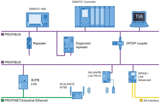
The PROFIBUS network offers wireless connection of several controllers, components and subnets as electrical network, optical network or by using links. Sensors and actuators are controlled centrally by means of PROFIBUS DP.
The example shows connection options to PROFIBUS DP:
7,$
'LDJQRVWLF UHSHDWHU DP/DP coupler Repeater 352),1(7,QGXVWULDO(WKHUQHW SIMATIC Controller $6,QWHUIDFH SIMATIC HMI 6&$/$1&( : ,:/$13% /LQN31,2 '3$6L/LQN $GYDQFHG ,(3% /LQN 352),%86 352),%86Figure 2-1 Connection options to PROFIBUS DP
Objectives of PROFIBUS DP
Distributed automation systems are increasingly used in production and process automation. This means a complex control task is divided up into smaller, more transparent subtasks with distributed control systems. This creates a high demand for communication between the distributed systems.
Distributed systems offer the following benefits:
● An independent and simultaneous commissioning of individual devices is possible. ● Small, manageable programs
● Parallel processing due to distributed automation systems ● Reduced response times
● Higher-level structures can take on additional diagnostic and logging functions.
● Increased plant availability because the rest of the overall system can continue to work when a subordinate station fails.
2.1.2
PROFIBUS terminology
Definition: Devices in the PROFIBUS environment
In the PROFIBUS environment, "device" is the generic term for: ● Automation systems (for example, PLC, PC)
● Distributed I/O systems
● Field devices (for example, hydraulic devices, pneumatic devices)
● Active network components (e.g., diagnostic repeater, optical link module) ● Gateways to AS interface or other fieldbus systems
Devices with PROFIBUS DP
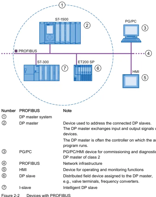
The figure below shows the most important components with PROFIBUS DP. The table below lists the designations of the individual components.
2 3 4 5 7 6 1 352),%86 6 6 (763 3*3& +0,
Number PROFIBUS Note
①
DP master system②
DP master Device used to address the connected DP slaves.The DP master exchanges input and output signals with field devices.
The DP master is often the controller on which the automation program runs.
③
PG/PC PG/PC/HMI device for commissioning and diagnostics DP master of class 2④
PROFIBUS Network infrastructure⑤
HMI Device for operating and monitoring functions⑥
DP slave Distributed field device assigned to the DP master,e.g., valve terminals, frequency converters.
⑦
I-slave Intelligent DP slaveOverview of I/O communication
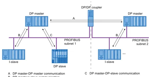
I/O communication is the reading or writing of inputs/outputs of the distributed I/O. The figure below gives you an overview of I/O communication using PROFIBUS DP:
$'3PDVWHU'3PDVWHUFRPPXQLFDWLRQ %'3PDVWHU,VODYHFRPPXQLFDWLRQ &'3PDVWHU'3VODYHFRPPXQLFDWLRQ '3PDVWHU '3VODYH '3PDVWHU ,VODYH ,VODYH 352),%86 VXEQHW 352),%86 VXEQHW '3'3FRXSOHU $ % & %
Figure 2-3 I/O communication using PROFIBUS DP
I/O communication is also available with the communication module (CM) or the interface module (IM) with integrated DP interface. These DP interfaces behave like integrated DP interfaces of the CPU.
I/O communication using PROFIBUS DP Table 2- 1 I/O communication using PROFIBUS DP
Communication between … Explanation
DP master and DP slave The data exchange between a DP master and DP slaves with I/O modules takes place as follows: The DP master queries the DP slaves of its master system one after the other and receives input values from the DP slaves and transmits output data to the DP slaves (master-slave principle).
DP master and I-slave A fixed number of data is transmitted cyclically between the user programs in CPUs of DP masters and I-slaves.
The DP master does not access the I/O modules of the I-slave, but instead accesses configured address areas, called transfer areas, that can be inside or outside the process image of the I-slave CPU. If parts of the process image are used as transfer areas, these may not be used for actual I/O modules.
Data transmission takes place with load and transfer operations using the process image or by direct access.
DP master and DP master A fixed number of data is transmitted cyclically between the user programs in CPUs of DP masters. A DP/DP coupler is required as additional hardware.
The DP masters mutually access configured address areas, called transfer areas, inside or outside the process images of the CPUs. If parts of the process image are used as transfer areas, these may not be used for actual I/O modules.
Data transmission takes place with load and transfer operations using the process image or by direct access.
Additional information
2.1.3
PROFIBUS DP interface
PropertiesA PROFIBUS device has at least one PROFIBUS interface with an electrical (RS 485) interface or optical (Polymer Optical Fiber, POF) interface.
Table 2- 2 Properties of the PROFIBUS DP interface
Standard PROFIBUS: IEC 61158/61784 Bus configuration / media PROFIBUS cables
(twisted two-wire lines RS 485 or fiber-optic cables) Transmission rate 9.6 kbps to 12 Mbps
Representation of the PROFIBUS DP interface in STEP 7
In the device view of STEP 7, the PROFIBUS DP interfaces for a DP master and a DP slave are highlighted by a purple rectangle:
2.2
Structure of PROFIBUS networks
Contents of this chapterThe following chapter provides background information on building your communication network.
● Overview of the most important passive network components: These are network components that forward a signal without the possibility of actively influencing it, for example, cables, connectors.
● Overview of the most important active network components: These are network components that actively affect a signal, for example, repeaters, diagnostic repeaters. ● Overview of the most common network structures (topologies)
Physical connections of industrial networks
PROFIBUS devices can be networked in industrial plants in two different physical ways: ● By means of electrical signals via copper cables
● By means of optical signals via fiber-optic cables
Selection criteria for networking
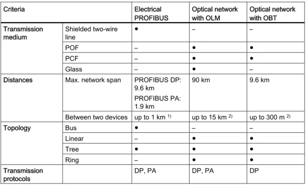
The table below includes selection criteria for electrical and optical networking of PROFIBUS devices:
Table 2- 3 Selection criteria for electrical and optical networking
Criteria Electrical
PROFIBUS Optical network with OLM Optical network with OBT Shielded two-wire line ● – – POF – ● ● PCF – ● ● Transmission medium Glass – ● –
Max. network span PROFIBUS DP: 9.6 km
PROFIBUS PA: 1.9 km
90 km 9.6 km Distances
Between two devices up to 1 km 1) up to 15 km 2) up to 300 m 2)
Bus ● – – Linear – ● ● Tree ● ● ● Topology Ring – ● ● Transmission protocols DP, PA DP, PA DP
Criteria Electrical
PROFIBUS Optical network with OLM Optical network with OBT
OLM – ● – Integrated interfaces ● – ● Bus terminal ● – ● Connection of devices by means of Bus connector ● – – Electrical network segments can be connected ● ● – ● Suitable
– Not relevant for this application
1) Depending on data rate and type of service used 2) Depending on cable type used
Installation guideline for PROFIBUS networks
A PROFIBUS segment must be terminated at the start and end; passively with a connector or actively with a bus terminating resistor.
The same principles apply to the installation of a PROFIBUS network as described in the SIMATIC NET PROFIBUS networks
2.2.1
Passive network components for RS 485 networks
2.2.1.1 RS 485 cablesIntroduction
The following applies to all RS 485 cables for PROFIBUS from Siemens:
● Their double shielding makes them especially suited for laying in industrial environments with electromagnetic interference.
● A continuous grounding concept can be implemented by means of the outer shield of the bus cable and the ground terminals of the bus terminals.
● The imprinted meter marking makes it easier to determine the length (accuracy ±5 %).
RS 485 cables for PROFIBUS
SIMATIC NET PROFIBUS cables are available in different versions which makes for an optimum adaptation to different areas of application:
● FC Standard Cable GP (bus cable for fixed laying inside buildings) ● FC Standard Cable IS GP (bus cable for hazardous area)
● FC-FRNC Cable GP (bus cable with halogen-free protective jacket for use inside buildings)
● FC Food Cable (bus cable with PE jacket for use in the food and beverage industry) ● FC Robust Cable (bus cable with PUR jacket for environments subject to chemical
and mechanical stress)
● FC Ground Cable (ground cable with PE jacket)
● PROFIBUS FC Trailing Cable (trailing cable for tow chains) ● PROFIBUS Festoon Cable (bus cable for festoon mounting)
● PROFIBUS Torsion Cable (torsion-free bus cable for networking movable plant parts, for example, robots)
● PROFIBUS FC Flexible Cable (bus cable for machine parts that are moved infrequently or cabinet doors)
● SIENOPYR-FR ship cable (for permanent laying on ships and off-shore units in all rooms and on open deck)
● PROFIBUS Hybrid Standard Cable (hybrid cable with 2 power wires (1.5 mm2)
for data and power supply of the ET 200pro)
● PROFIBUS Hybrid Robust Cable (trailable hybrid cable with 2 power wires (1.5 mm2)
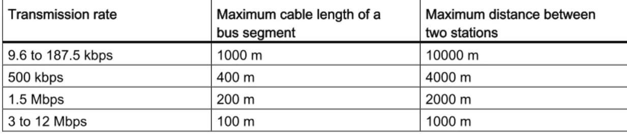
Maximum cable lengths
When using copper cables, the maximum size of a PROFIBUS segment depends on the transmission rate.
If these lengths are not sufficient for your application, you can expand the network by using repeaters. You can achieve a maximum size by cascading up to nine repeaters.
Table 2- 4 Maximum cable lengths
Transmission rate Maximum cable length of a
bus segment Maximum distance between two stations 9.6 to 187.5 kbps 1000 m 10000 m
500 kbps 400 m 4000 m
1.5 Mbps 200 m 2000 m
3 to 12 Mbps 100 m 1000 m
2.2.1.2 PROFIBUS FastConnect system PROFIBUS FastConnect (FC)
PROFIBUS FastConnect is a system for fast and easy fabrication of PROFIBUS copper cables.
The system consists of three components: ● FastConnect bus cables for quick mounting ● FastConnect stripping tool
● FastConnect bus connector for PROFIBUS with insulation displacement method
FastConnect bus cables and stripping tool
The special design of the FastConnect bus cables allows for the use of the FastConnect stripping tool to accurately strip away the outer jacket and the braided shield in one step. The connection of the prepared cables takes place in the FastConnect bus connectors using the insulation displacement method.
All PROFIBUS FastConnect bus cables can also be connected to the conventional bus connectors with screw-type terminals.
Area of application
You need FastConnect bus connectors for PROFIBUS for the following applications: ● Connect devices with an electrical 9-pin D-Sub interface to IEC 61158-2 directly with
SIMATIC NET PROFIBUS cables.
● Connect electrical segments or individual devices to the Optical Link Module (OLM) and Optical Bus Terminal (OBT).
● Connect devices or programming devices to the repeater.
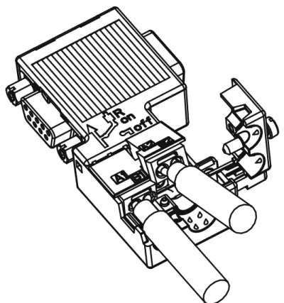
Versions
The FastConnect bus connector in degree of protection IP20 is available in the following versions:
● with integrated terminating resistor and isolating function ● with or without PG socket
● with a cable outlet of 35°, 90° or 180°
● with device category 3G suitable for hazardous area of zone 2
Figure 2-5 Example for PROFIBUS FastConnect bus connector with PG socket, cable outlet 90°
Additional information
For additional information on the available components visit the Siemens Mall
2.2.1.3 PROFIBUS bus connector Area of application
You need PROFIBUS bus connectors for the following applications:
● Connect devices with a 9-pin D-Sub interface to IEC 61158-2 directly with the SIMATIC NET PROFIBUS cables.
● Connect electrical segments or individual devices to the Optical Link Module (OLM) and Optical Bus Terminal (OBT).
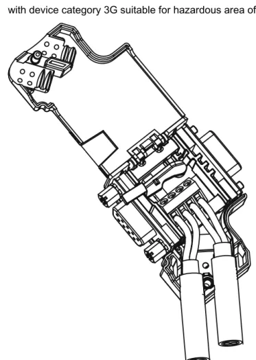
Versions
The PROFIBUS bus connector in degree of protection IP20 is available in the following versions:
● with integrated terminating resistor and isolating function ● with or without PG socket
● with a cable outlet of 35°, 90° or 180°
● with device category 3G suitable for hazardous area of zone 2
Figure 2-6 Example for PROFIBUS bus connector with PG socket, cable outlet 35°
Additional information
For additional information on the available components visit the Siemens Mall
2.2.1.4 M12 bus connector Area of application
Devices with an electrical M12 interface can use the M12 bus connector for
SIMATIC NET PROFIBUS for direct connection with the SIMATIC NET PROFIBUS cables. The M12 bus connector in degree of protection IP65 is available in the following versions: ● with screw-type terminals
● with insulation displacement termination ● with a cable outlet of 180°
2.2.1.5 Bus terminals for RS 485 networks Bus terminal RS 485 and bus terminal M12
A bus terminal is used for the connection of an individual PROFIBUS station with RS485 interface to the PROFIBUS bus cable.
Bus terminals in degree of protection IP20 are available in the following versions:
● Bus terminal RS 485 with or without PG interface, transmission rate 9.6 kbps to 1.5 Mbps, integrated terminating resistor combination (connectible), with 1.5 m and 3 m connecting cable
● Bus terminal M12, transmission rate 9.6 kbps to 12 Mbps, integrated terminating resistor combination with isolating function, with 1.5 m connecting cable
2.2.1.6 M12 bus terminating resistor Terminating segment with terminating resistor
If there is a station with M12 connection system at the beginning or end of a PROFIBUS segment, you need an M12 bus terminating resistor.
The M12 PROFIBUS connection of a device consists of an M12 socket for the infeed and an M12 male connector to loop-through the bus signal.
This means you need one bus terminating resistor with male contacts (6GK1905-0EC00) and with female contacts (6GK1905-0ED00) for each M12 bus cable.
2.2.2
Passive components for optical networks
2.2.2.1 Fiber-optic cablesTypes of fiber-optic cables
Data transmission with fiber-optic cables takes place through modulation of electromagnetic waves in the range of visible and invisible light. These cables are made of high-quality plastic fibers and glass fibers:
● Plastic and PCF fiber-optic cables (Page 25) ● Glass fiber-optic cables (Page 26)
The different types of fiber-optic cables provide solutions matched to the operating and environmental conditions for the connection of components with each other.
Benefits
Fiber-optic cables offer the following benefits when compared with electrical cables: ● Galvanic isolation of the devices and segments
● No potential equalization currents
● No impact on transmission path through external electromagnetic interference ● No lightning protection elements required
● No noise radiation along the transmission route ● Low weight
● Depending on the type of fiber you can implement cable lengths up to few kilometers at even higher transmission rates.
● No dependency of the maximum permitted distances on the transmission rate
Additional information
Additional information of the properties and technical specifications of the passive components and connectors for fiber-optic cables is available in the PROFIBUS network
2.2.2.2 Plastic and PCF fiber-optic cables Plastic and PCF fiber-optic cables
Plastic (POF) and PCF fiber-optic cables are used for the connection of Optical Link
modules with connections for plastic fiber-optic cables (OLM/P), Optical Bus Terminal (OBT) and devices with integrated optical interfaces. Under certain conditions, they are an
inexpensive alternative to conventional glass fiber-optic cables.
Plastic Fiber Optic duplex core
The plastic fiber-optic duplex core is a flat dual core with PVC inner jacket without protective jacket. The cable can be easily assembled on-site.
The cable is intended for indoor applications with low mechanical loads or inside cabinets. For OLM connections and with integrated optical interfaces you cover a length of up to 50 m between two devices with this cable.
Plastic Fiber Optic standard cable
The plastic fiber optic standard cable consists of two plastic fibers with robust polyamide inner jacket surrounded by Kevlar tensile elements and a purple PVC protective jacket. The cable can be easily assembled on-site.
The robust round cable is suited for indoor applications. The maximum distance that can be covered is 80 m for OLM/P connections and 50 m with integrated optical interfaces and OBT.
PCF Standard Cable
The pre-assembled PCF Standard Cable consists of two PCF fibers surrounded by Kevlar tensile elements and a purple PVC protective jacket. It is always supplied with a pulling aid installed on one end to pull in the cable channels.
The robust round cable is suited for indoor applications with cable lengths up to 400 m (OLM) or 300 m (integrated optical interfaces, OBT) between two devices.
PCF Standard Cable GP
The PCF Standard Cable GP consists of two PCF fibers surrounded by Aramid tensile elements and a green PVC protective jacket. The cable is pre-assembled and can be ordered by the meter. It is supplied with a pulling aid installed on one end to pull in the cable channels.
The robust round cable is suited for indoor and outdoor applications with cable lengths up to 400 m (OLM) or 300 m (integrated optical interfaces, OBT) between two devices.
PCF Trailing Cable
The PCF Trailing Cable consists of two PCF fibers surrounded by Aramid tensile elements and a green PUR protective jacket. The cable is pre-assembled and can be ordered by the meter. It is supplied with a pulling aid installed on one end to pull in the cable channels. The robust round cable is suited for moving indoor and outdoor applications with cable lengths up to 400 m (OLM) or 300 m (integrated optical interfaces, OBT) between two devices.
PCF Trailing Cable GP
The PCF Trailing Cable GP consists of two PCF fibers surrounded by Aramid tensile elements and a green PVC protective jacket. The cable is pre-assembled and can be ordered by the meter. It is supplied with a pulling aid installed on one end to pull in the cable channels.
The robust round cable is suited for moving indoor and outdoor applications with cable lengths up to 400 m (OLM) or 300 m (integrated optical interfaces, OBT) between two devices.
2.2.2.3 Glass fiber-optic cables Glass fiber-optic cables
Glass fiber-optic cables are suitable for connection of optical interfaces that work in the wavelength range around 850 nm and around 1300 nm. They include two graded-index multimode fibers of the type 62.5/125 μm.
The glass fiber-optic cables are available in different versions which makes for an optimum adaptation to different areas of application:
● Fiber Optic standard cable ● INDOOR Fiber Optic indoor cable ● Flexible Fiber Optic trailing cable
Fiber Optic standard cable
The standard cable is the universal cable for indoor and outdoor use.
INDOOR Fiber Optic indoor cable
The indoor cable is intended for weather-proof indoor use. It is halogen-free, non-crush and flame-retardant.
Flexible Fiber Optic trailing cable
The trailing cable was designed for the special application of forced movement, for example, for constantly moved machine parts such as trailing chains. It is mechanically designed for 100,000 bending cycles by ±90° (with the specified minimum radius). Integrated dummy elements ensure a round cross-section of the cable. The trailing cable can be used indoors and outdoors.
Maximum distances between two optical link modules
The following distances may not be exceeded between two OLMs regardless of the optical power budget:
● OLM/P11, OLM/P12: 400 m
● OLM/G11, OLM/G12, OLM/G12-EEC: 3 km ● OLM/G11-1300, OLM/G12-1300: 15 km
Additional information
All operating instructions
(
SIMATIC NET bus components include information on distances that can be covered with the SIMATIC NET glass fiber-optic cables. You can configure your optical network without any calculations using simple limits.
2.2.3
Active network components
2.2.3.1 Network components in electrical networks Active network components
The following active network components are available for PROFIBUS in electrical networks: ● Repeater RS485 ● Diagnostic repeater ● PROFIBUS Terminator ● DP/DP coupler ● IE/PB Link PN IO ● IWLAN/PB Link PN IO
● Active components for the connection of CAN
● Active components for the gateway between PROFIBUS and AS-Interface – DP/AS-i LINK Advanced
– DP/AS-Interface Link 20E – DP/AS-i F-Link
RS485 repeater
The RS485 IP20 repeater connects two PROFIBUS bus segments in RS485 technology with up to 32 devices. It provides transmission rates from 9.6 kbps to 12 Mbps.
The RS485 repeater refreshes a signal regarding amplitude, signal width and edge steepness between two segments. It is used when more than 32 stations are connected to the bus or the maximum cable length of a segment is exceeded.
Bus segments can be operated ungrounded (galvanic isolation of segments) with a RS485 repeater.
Diagnostic repeater
The diagnostic repeater connects three PROFIBUS segments in RS485 technology, two of which are diagnostics-capable segments with 31 devices each. It is designed as DP slave to send diagnostic messages to the DP master.
The diagnostic function provides the location and the cause of cable faults, such as wire break or missing terminating resistors. The fault location is indicated relative to the existing devices.
The diagnostic repeater refreshes a signal regarding amplitude, signal width and edge steepness between two segments. The cascading depth between any two PROFIBUS devices is limited to nine diagnostic repeaters.
PROFIBUS Terminator
The PROFIBUS Terminator forms an active bus termination. Bus devices can be switched off, removed or replaced without affecting data transmission. This is particularly true for bus devices on both ends of the bus cable at which terminating resistors must be connected or supplied. The PROFIBUS Terminator can be mounted on a standard mounting rail.
IE/PB Link PN for the connection of a PROFIBUS segment to an Industrial Ethernet network
The IE/PB Link PN IO as independent component provides the seamless transition between Industrial Ethernet and PROFIBUS. By using the IE/PB Link PN IO as substitutes on the Ethernet, the existing PROFIBUS devices can still be used and integrated into a PROFINET application.
A PROFINET IO controller is required for this configuration. The IE/PB Link PN acts as master on the PROFIBUS end.
IWLAN/PB Link PN IO as gateway between LAN and PROFIBUS
PROFIBUS devices can be coupled to PROFINET IO by means of IWLAN/PB Link PN IO. This means you can integrate existing PROFIBUS configurations into PROFINET.
The IWLAN/PB Link PN IO supports the use of IWLAN and WLAN antennas for wireless data transmission, for example, in suspended monorail systems or conveyor systems. By supporting PROFINET, the numerous PROFIBUS system services,
for example, diagnostic by bus, can still be used.
A PROFINET IO controller is required for this configuration. The IWLAN/PB Link PN IO acts as master on the PROFIBUS end.
CANopen module for connection to CAN
You can use the CANopen module to easily connect CANopen applications to PROFIBUS. Typical areas of application:
● Control of hydraulic valves / hydraulic axles in vehicles
● Control of motors in packaging machines and on conveyor belts ● Use in wind turbines for detection of angular encoders
● Detection of HMI devices on machines, e.g., joysticks
● Detection of measured data from displacement transducers, inclination sensors or angle encoders on tower cranes or gantry cranes
DP/PA bus link for connection of PROFIBUS PA
The DP/PA bus link is the connection between PROFIBUS DP and PROFIBUS PA. This means it connects the process control systems with the field devices of the process automation.
The following components are available for a DP/PA bus link: ● DP/PA coupler Ex [ia]
● DP/PA coupler FDC 157-0
● Interface module IM 153-2 for establishing a DP/PA link. ● Active field distributor AFDiS for hazardous areas
Active components for the gateway between PROFIBUS and AS-Interface
● DP/AS-i LINK Advanced
The DP/AS-i LINK Advanced is PROFIBUS DPV1 slave (to IEC 61158-2 / EN 61158-2) and AS-Interface master (to AS-Interface-specification V3.0 to EN 50295) and provides transparent data access to AS-Interface from PROFIBUS DP.
PROFIBUS DP masters can cyclically exchange I/O data with the AS-Interface; DP masters with acyclical services can also make AS-Interface master calls. The DP/AS-i LINK Advanced is particularly suited for distributed configurations and for the connection of a subordinate AS-Interface network.
The DP/AS-i LINK Advanced in the version as AS-Interface single master is completely sufficient for applications with typical quantity structures.
For applications with high quantity structures, the DP/AS-i LINK Advanced is used as AS-Interface double master. In this case, the duplicate quantity structures can be used on two independently running AS-Interface strands.
● DP/AS-Interface Link 20E
The DP/AS-Interface Link 20E is PROFIBUS DP slave (in accordance with EN 61158) and AS interface master (in accordance with AS interface specification V3.0 according to EN 50295) and supports operation of the AS-Interface on PROFIBUS DP.
Single PROFIBUS masters can cyclically exchange I/O data with the AS interface; masters with acyclical services can exchange I/O data and make master calls. ● DP/AS-i F-Link
The DP/AS-i F-Link is PROFIBUS DP-V1 slave (to EN 61158) and AS-i master
(to AS-Interface-specification V3.0 to EN 50295) and provides transparent data access to AS-Interface from PROFIBUS DP. The DP/AS-i F-Link is also the only AS-i master that can forward safety-oriented input data of ASIsafe slaves to a fail-safe CPU with
PROFIBUS DP master by means of the PROFIsafe protocol. An additional safety cabling or monitoring is not required (especially no AS-Interface safety monitor). Depending on the slave type, you can transmit binary values or analog values. All slaves to AS-Interface specification V2.0, V2.1 or V3.0Als can be operated as AS-i slaves.
As fully adequate AS-i master to specification V3.0, you can use higher quantity structures on the AS-i network (496 inputs and outputs each, up to 62 digital or analog slaves).
Additional information
Information on the components is available in the Siemens Mall
(
Additional information is available in these manuals: ● PROFIBUS network manual
(
● Diagnostic repeater
● DP/DP coupl
● SIMATC NET Twisted-Pair and Fiber-Optic Networks
(
● Basics for installation of an Industrial Wireless LAN
(
● SIMATIC bus links, DP/PA coupler, active field distributors, DP/PA Link and Y Link
(
● Information on the CANopen module is available on the Internet
(
● DP/AS-INTERFACE LINK Advanced
() manual
● DP/AS-i F-Link) manual
See also
Topology with RS485 repeater (Page 34) OLM topology (Page 39)
WLAN topology (Page 39)
2.2.3.2 Network components in optical networks Active network components
The following active network components are available for PROFIBUS in optical networks: ● Optical Link Module OLM
● Optical Bus Terminal OBT
Optical Link Module OLM
You can use the PROFIBUS Optical Link Modul OLM to install PROFIBUS networks in line, star structure and redundant ring structure.
The transmission rate of a fiber-optic cable line does not depend on the distance and can be 9.6 kbps to 12 Mbps.
Applications for OLM include, for example, plant buses on PROFIBUS base, networking across buildings using glass fiber-optic cables, mixed networks with electrical and optical segments, large networks (road tunnels, traffic guidance systems) and networks with high demands on availability (redundant ring networks).
Optical Link modules can be combined by means of an RS485 interface and individual devices or entire electrical segments can be integrated into the optical PROFIBUS network. The following distances may not be exceeded between two OLMs regardless of the optical power budget:
● OLM/P11, OLM/P12: 400 m
● OLM/G11, OLM/G12, OLM/G12-EEC: 3 km ● OLM/G11-1300, OLM/G12-1300: 15 km
Optical Bus Terminal OBT (optical bus terminal)
The Optical Bus Terminal connects an individual PROFIBUS device without integrated optical interface or a PROFIBUS RS 485 segment with up to 31 devices to an optical PROFIBUS.
An individual PROFIBUS DP device is connected with its RS 485 interface by means of a PROFIBUS cable with integrated terminating resistor, for example, connecting cable 830-1T, to the RS 485 interface of the OBT. The OBT is integrated into the optical line by means of two optical interfaces.
The following optical transmission media can be connected to the OBT: ● Plastic fiber-optic cable up to 50 m single distance length.
They can be assembled on-site with two 2x2 Simplex connectors. ● PCF fiber-optic cable up to 300 m single distance length.
Additional information
Information on the components is available in the Siemens Mall
(
Additional information is available in these manuals: ● PROFIBUS network manual
(
● SIMATIC NET PROFIBUS, Optical Link Module
()
● SIMATC NET Twisted-Pair and Fiber-Optic Networks
2.2.4
Examples for topology
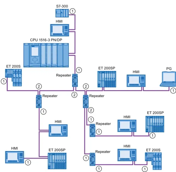
2.2.4.1 Topology with RS485 repeater Configuration options with the RS485 repeaterYou can operate the RS485 repeater in the following configurations:
6HJPHQW 6HJPHQW Repeater
Figure 2-7 Segment 1 and segment 2 connected to RS485 repeater
6HJPHQW 6HJPHQW Repeater
Figure 2-8 Segment 1 and segment 2 looped-through to RS485 repeater
6HJPHQW 6HJPHQW Repeater
Figure 2-9 Segment 1 connected to RS485 repeater and segment 2 looped-through to RS485 repeater
①
Connect terminating resistorConfiguration example PG Repeater HMI HMI HMI HMI HMI HMI Repeater Repeater Repeater Repeater S7-300 ET 200SP ET 200SP ET 200S ET 200S ET 200SP &3831'3
Figure 2-10 Configuration example with five RS485 repeaters
①
Connect terminating resistor②
Do not connect terminating resistorMaximum configuration
If you install a PROFIBUS network with RS485 repeaters, you may not connect more than nine RS485 repeaters in series.
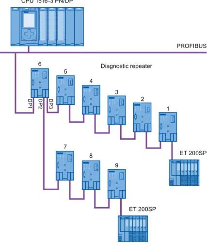
2.2.4.2 Topology with diagnostic repeater Diagnostic repeater with three segments
You may not exceed the maximum permitted cable length of 100 m per segment that can be monitored for the diagnostic repeater. The segments connected to DP2 and DP3 are diagnostics-capable. The cable length that can be monitored is limited for some cable types.
Maximum cascade depth
You can connect up to nine diagnostic repeaters in series between any two PROFIBUS stations. 'LDJQRVWLFUHSHDWHU 352),%86 '3 '3 '3 (763 (763 &3831'3
Figure 2-11 Schematic layout of a PROFIBUS network with maximum possible cascade depth at diagnostic repeaters
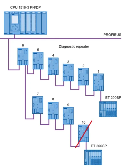
Example: Maximum cascade depth exceeded 'LDJQRVWLFUHSHDWHU 352),%86 (763 (763 &3831'3
Layout with several segments
You can increase the number of used diagnostic repeaters by using several segments. The example shows a layout in which the maximum cascade depth is exceeded at two segments.
&3831'3 (763 (763 (763 (763
Figure 2-13 Layout with several segments, maximum cascade depth exceeded
Additional information
Additional information is available in the Diagnostic Repeater
2.2.4.3 OLM topology
Combination of electrical and optical networks with OLM
Additional distances can be covered by means of the Optical Link Module.
Because bus cables across several buildings are particularly vulnerable to damage caused by overvoltage (effect of lightning), the devices in the connected bus segment must be protected against overvoltage.
%XLOGLQJ 352),%86 WHUPLQDWRU 352),%86 WHUPLQDWRU %XLOGLQJ 2SWLFDO QHWZRUN (OHFWULFDOQHWZRUN (OHFWULFDOQHWZRUN &3831'3 &3831'3 2/0 2/0 56 56
Figure 2-14 Combination of electrical and optical networks
2.2.4.4 WLAN topology
IWLAN/PB Link PN IO as gateway between Industrial Wireless LAN and PROFIBUS
The IWLAN/PB Link PN IO supports the use of IWLAN and WLAN antennas for wireless data transmission. This means the numerous PROFIBUS system services, for example, diagnostic by bus, can be used throughout.
,:/$13%
352),1(7 352),%86
6&$/$1&( :
2.2.4.5 Connecting PROFIBUS to PROFINET
PROFIBUS can be integrated in PROFINET. In this way, you can set up any hybrid systems consisting of fieldbus and Ethernet-based subsystems. This provides a continuous data exchange.
Coupling of PROFIBUS and PROFINET
With a proxy-capable PROFINET device that is equipped with a PROFIBUS interface in addition to a PROFINET interface, you can integrate existing PROFIBUS configurations into the PROFINET configuration.
3*3& 352),1(7,QGXVWULDO(WKHUQHW ,(3% /LQN 352),%86 6 (763 (763 (763 (763
Figure 2-16 Connection of PROFIBUS and PROFINET with IE/PB link
PROFINET device with proxy functionality
The PROFINET device with proxy functionality is the substitute for a PROFIBUS device on Ethernet. The proxy functionality allows a PROFIBUS device to communicate not only with its master but also with all devices on PROFINET.
With PROFINET, existing PROFIBUS systems can be integrated into the PROFINET communication with the aid of an IE/PB link. The IE/PB link PN IO then handles communication via PROFINET on behalf of the PROFIBUS components.
Parameter assignment/addressing
3
To set up an automation system, you will need to configure, assign parameters and link the individual hardware components. The work needed for this is undertaken in the STEP 7 device, topology and network view.
Configuration
"Configuring" is understood to mean arranging, setting and networking devices and modules within the device or network view.
A PROFIBUS address is automatically assigned to each module. The addresses can be subsequently modified.
The CPU compares the preset configuration created in STEP 7 with the actual configuration of the plant. Errors can be detected and signaled immediately this way.
The exact procedure for configuring devices is described in detail in the STEP 7 online help.
Parameter assignment
"Parameter assignment" is understood to mean setting the properties of the components used. The settings for the hardware components and for data exchange are assigned, for example, activating diagnostics, input delay with DI.
The parameters are downloaded into the CPU and transferred to the corresponding modules when the CPU starts up. Modules can be replaced with ease because with SIMATIC CPUs the set parameters are automatically downloaded into the new module during each startup.
Adjusting the hardware to the project requirements
You need to adapt the hardware if you want to set up, expand or change an automation project. To do this, add hardware components to your layout, link them with existing components, and adapt the hardware properties to the tasks.
The properties of the automation systems and modules are preset so that in many cases you do not have to assign parameters again.
But parameter assignment is required in the following cases: ● You want to change the preset parameters of a module. ● You want to use special functions.
Basic procedure for creating a PROFIBUS DP system
● Configuration
– Creating PROFIBUS devices and modules in STEP 7 – Assigning the DP slave to a DP master (Page 42) ● Optional: Parameter assignment
– Assigning the PROFIBUS address (Page 44) – Making network settings (Page 45)
– Considering cable configuration (Page 48) – Considering additional network devices (Page 50)
– Bus parameters – creating a user-defined profile (Page 51) – Configuring constant bus cycle time (Page 54)
3.1
Assigning the DP slave to a DP master
PROFIBUS DP system
A PROFIBUS DP system consists of a PROFIBUS DP master and its assigned
PROFIBUS DP slaves. Once the devices have been placed in the network view or device view, STEP 7 assigns default parameter values to them. Initially, you only have to assign the DP slaves to one DP master.
Requirement
● The network view of STEP 7 is open.
● A CPU has been placed (e.g., CPU 1516-3 PN/DP). ● A DP slave has been placed (e.g., IM151-1 HF).
Procedure
To assign DP slaves to a DP master, follow these steps:
1. On the DP slave, use the left mouse button to click on the "Not assigned" link. The "Select DP master" menu opens.
2. Select the DP master in the menu to which you want to assign the DP slave. Result: A subnet with a DP system is created on the CPU. The CPU is now the PROFIBUS DP master. The DP slave is assigned to the DP master.
3. Repeat steps 1 and 2 for all other DP slaves that you want to assign to the DP master.
Figure 3-1 Assigning the DP slave to a DP master
Network overview
You can check the communication relationships of the activated interface in the network overview. The network overview is context-sensitive for selection in the network view: ● The selection of the CPU shows the DP communication of the CPU.
● The selection of the station shows the communication of the entire station. ● The selection of the interface shows the DP communication of the interface.
3.2
PROFIBUS address
Devices can be connected to the PROFIBUS subnet that communicate by means of configured connections or that are part of a PROFIBUS DP master system. If the DP slave has already been assigned to a DP master, the PROFIBUS subnet to which the device is connected is automatically displayed under "Interface linked with". In the Inspector window under "PROFIBUS", select the subnet to which the interface is linked or add a new subnet.
All devices of a subnet must have different PROFIBUS addresses.
Figure 3-2 PROFIBUS address
Rules for address assignment
STEP 7 automatically assigns device addresses.
You can change the addresses if you observe the following points:
● Assign a unique PROFIBUS address to each device in the PROFIBUS network, each DP master and each DP slave in the PROFIBUS network.
● Depending on the DP slave, not all permitted PROFIBUS addresses are supported. For devices with BCD switches, it is often the case that only the PROFIBUS
addresses 1 to 99 are supported.
Changing the PROFIBUS address
3.3
Network settings
Highest PROFIBUS address (HSA)Outputs the highest PROFIBUS address of an active device. PROFIBUS addresses greater than HSA are permitted for passive devices, but only up to 126.
Profile
Depending on the connected device types and the protocols used, different profiles are available on the PROFIBUS. The profiles differ with respect to their setting options and calculation of the bus parameters.
The PROFIBUS subnet will only work properly if the bus parameters of all devices have the same values.
Figure 3-3 Network settings
Profiles and transmission rates
Table 3- 1 Profiles and transmission rates
Profiles Supported transmission rates
DP 9.6 kbps to 12 Mbps
Standard 9.6 kbps to 12 Mbps Universal (DP/FMS)
(FMS is not supported) 9.6 kbps to 1.5 Mbps User-defined 9.6 kbps to 12 Mbps
DP (recommended profile)
Select the "DP" profile if only devices meeting the requirements of the standard
EN 61158-6-3 are connected to the PROFIBUS subnet. The setting of the bus parameters has been optimized for these devices. These include devices with DP master and DP slave interfaces of SIMATIC S7 as well as distributed I/O devices from third parties.
Note
Profile for constant bus cycle time and isochronous mode
DP is the recommended profile for the configuration of constant bus cycle time and isochronous mode.
Standard
Compared with the "DP" profile, the "Standard" profile gives you the option to take into consideration devices of another project or devices that have not been configured here for calculation of the bus parameters. The bus parameters are then calculated with a simple algorithm that was not optimized.
Universal (DP/FMS) (FMS is not supported)
Select the "Universal (DP/FMS)" profile if individual devices in the PROFIBUS subnet use the FMS service (e.g., CP 343-5, PROFIBUS FMS devices).
As with the "Standard" profile, here, too, you have the option to take additional devices into consideration for calculation of the bus parameters.
User-defined
The PROFIBUS subnet will only work properly if the parameters for the profile have been synchronized. Select the "User-defined" profile if none of the other profiles "match" for operation of a PROFIBUS device and if you have to adapt the bus parameters for your special layout.
You cannot configure all theoretically possible combinations with the user-defined profile either. The PROFIBUS standard prescribes some parameter limits depending on other parameters. It is, for example, not permitted that a responder responds (Min Tsdr) before the initiator is able to receive the frame (Trdy). These standard specifications are also checked in the "User-defined" profile.
Note
User-defined settings
Use user-defined settings only if you are familiar with the PROFIBUS parameters. It is usually better to work with the "DP" profile.
Contact Customer Support (Page 79) if you have any questions.
The bus parameters that were last valid on the PROFIBUS subnet are automatically set as user-defined. If the "DP" bus profile was valid for the subnet, for example, the bus
parameters for "DP" are set in the "User-defined" bus profile. You can modify the parameters based on these settings.
The monitoring times are not automatically recalculated in the "User-defined settings" setting so that the uniformity of the set values is not changed without your knowledge, for example, to configure other configuration tools.
You can calculate the monitoring times Ttr and watchdog based on the parameters you have set. To do so, click on the "Recalculate" button.
See also
3.4
Cable configuration
Considering cable configurationInformation on the cable configuration can be taken into consideration for calculation of the bus parameters. To do so, select the check box "Consider following cable configuration" in the properties of the PROFIBUS subnet.
The other information depends on the type of cable used.
Figure 3-4 Cable configuration
Cable configuration: Fiber-optic cables / optical ring
The calculation depends on the used OLM types. Select the corresponding check box. Multiple selections are possible.
Adapt bus parameters in the optical ring
With the layout as ring, there is a kind of redundancy because you have the option to address all devices using the ring structure even if the connection to other devices is interrupted.
The following configuration conditions must be met in the optical ring: ● A free address below HSA (Highest Station Address)
● Increasing the retry value to at least 3 (Network settings: user-defined profile) ● Checking and adapting the slot time
(Network settings: user-defined profile; bus parameters: Tslot parameter:
You need short slot time values for OLM / P12, median slot time values for OLM / G12 and OLM / G12-EEC and high slot time values for OLM / G12-1300. This results in a high performance for small networks and a medium to low performance with medium to large networks.
Additional information
Additional information on adaptation of the retry value and the slot time is available in the PROFIBUS network manual
3.5
Additional network stations
Communication load - considering additional network stations
The bus parameters depend on the communication volume of the active network stations. There are differences between cyclical communication (DP) and connection-oriented, acyclical communication (S7 communication, Send/Receive (FDL)). Contrary to DP, the number and size of the communication jobs (communication load) depends on the user program. This means the communication load cannot always be determined automatically. If you select the check box "Consider the following network stations", you can consider network stations in the calculation of the bus times that were not configured in the project.
Figure 3-5 Additional network stations
Calculating the bus times
You can specify a network configuration in the parameter group "Additional network stations" for calculation of the bus times that deviates from the configured network configuration. The network configuration is available for the following profiles:
● Standard
● Universal (DP/FMS) ● User-defined
Quantification of the communication load
The following settings are possible to take the communication load into consideration: ● Number of network stations that are not configured
● Information on the communication load from the user programs for FDL or S7 communication. You can choose from the following levels:
– Low: Typical for DP, no larger data communication except DP.
– Medium: Typical for mixed operation of DP and other communication services (e.g., S7 communication), if DP has high time requirements and with medium, acyclical communication volume.
– High: For mixed operation of DP and other communication services (e.g., S7 communication), if DP has low time requirements and with high, acyclical communication volume.
3.6
Bus parameters
Introduction
Bus parameters control the transmission behavior on the bus.
Each device on the bus must correspond with the bus parameters of other devices. Note
The PROFIBUS subnet will only work properly if the parameters for the bus profile have been synchronized. Change the preset values only if you are familiar with the parameter assignment of the bus profile for PROFIBUS.
Cyclical distribution of the bus parameters
If the check box "Activate cyclical distribution of bus parameters" is selected under "Bus parameters" with the selected PROFIBUS subnet in the Inspector window, the bus parameters are sent cyclically during operation by the modules that support this function. This way you can, for example, connect a programming device to the PROFIBUS during operation.
Disable this function in the following cases:
● In constant bus cycle time mode to minimize the bus cycle.
● If third-party devices are connected in the PROFIBUS subnet whose protocol uses the DSAP 63 (Destination Service Access Point) for multicast.
Bus parameters for the bus profile of PROFIBUS subnets
Note
Display of offline values
The offline values of the bus parameters are always displayed even if they are connected online with the target system.
Table 3- 2 Bus parameters - value ranges
Bus parameters Adjustable 1 Limit values
Tslot_Init Yes Max. Tsdr + 15 <= Tslot_Init <= 16.383 t_Bit Max. Tsdr Yes 35 + 2*Tset + Tqui <= Max. Tsdr <= 1,023 t_Bit Min. Tsdr Yes 11 t_Bit <= Min. Tsdr <= MIN(255 t_Bit, ...
... Max. Tsdr - 1, 34 + 2*Tset + Tqui) Tset Yes 1 t_bit <= Tset <= 494 t_bit
Tqui Yes 0 t_bit <= Tqui <= MIN(31 t_bit, Min. Tsdr - 1) GAP factor Yes 1 <= GAP factor <= 100
Retry limit Yes 1 <= Retry limit <= 15 Tslot ( slot time) No -
Tid2 No Tid2 = Max. Tsdr Trdy No Trdy = Min. Tsdr
Tid1 No Tid1 = 35 + 2*Tset + Tqui
Ttr (Target Rotation Time) Yes 256 t_Bit <= Ttr <= 16,777,960 t_bit
Ttr typical No This time is for information only and is not transmitted to the devices.
Watchdog 10 ms <= Watchdog <= 650 s
1 depending on bus profile
User-defined bus profile
Use the following settings to create a user-defined bus profile: ● minimum Target Rotation Time (Ttr) = 5000x HSA
(highest PROFIBUS address of an active device) ● minimum watchdog (Watchdog) = 6250x HSA
3.7
Constant bus cycle time
Constant bus cycle timeThe DP master addresses its assigned DP slaves cyclically. S7 communication may cause the intervals to vary. You can enable a "bus cycle with constant bus cycle time" to achieve identical intervals. This ensures data transmission at the same (constant bus cycle time) intervals.
Figure 3-7 Enabling a bus cycle with constant bus cycle time
Number of OPs/PGs/TDs at the PROFIBUS
Increasing DP cycle time manually
The following situation can occur especially with very short DP cycle times: The runtime of the user program is greater than the shortest cycle
(see Technical specifications of the CPU, section "Isochronous mode").
You have to manually increase the automatically calculated DP cycle time in this case.
See also
Diagnostics
4
4.1
Overview
Diagnostic options
In case of an error you can determine the current status of your automation system
and react specifically by using the event-related diagnostics and the evaluation of interrupts. You can use the following options for diagnostics of the PROFIBUS components:
● Determine the status of the system using the Lifelist in STEP 7.
● Evaluate the module status, error and message texts by using the display of the S7-1500 CPU.
● Run cable diagnostics during operation by means of the diagnostic repeater. ● Evaluate the diagnostics and interrupt behavior in isochronous mode. (Page 69) ● Determine status information for fault localization and fault rectification by using the
DP/PA coupler FDC 157-0 configured as PROFIBUS diagnostic slave.
Additional information
Additional information on diagnostics is available in these manuals: ● In the Diagnostic repeater for PROFIBUS-DP
(
with STEP 7, diagnostics in the user program, monitoring function isochronous PROFIBUS, topology display in STEP 7.
● In the System diagnostics
(
diagnostic options that are available for the automation systems S7-1500, ET 200MP and ET 200SP.
● )
network manual for diagnostics of fiber-optic cables.
● In the DP/PA coupler, active field distributors, DP/PA Link and Y Link
(
● In the Web server ()
4.2
Diagnostics using the display of the S7-1500
DisplaysEach CPU in the S7-1500 automation system has a front cover with a display and operating buttons. Control and status information is displayed in different menus on the display. You use the operating buttons to navigate through the menus.
The following states can be evaluated on the display: ● Module status for central and distributed modules
● Error and alarm texts (system diagnostics, user-defined alarms)
Module status
From the station overview you go to the module status for a distributed module via the module overview.
Error and alarm texts
Figure 4-2 Example: Diagnostic buffer, alarms
Additional information
Additional information on the topic "Functions and operation of the display" is available in the documentation for the S7-1500 automation system on the Internet
(
4.3
Diagnostics with the diagnostic repeater
Introduction
The diagnostic repeater is a repeater that can monitor two segments of a RS485-PROFIBUS subnet (copper cable) during operation and signal cable faults to the DP master by sending a diagnostic frame. Fault location and the cause of the fault can be displayed in plain text by means of STEP 7 as well as operator control and monitoring devices (SIMATIC HMI). With its cable diagnostics during operation, the diagnostic repeater allows you to detect and localize cable faults early on. This means plant faults are detected early and plant downtimes can be prevented.
Diagnostic functions
● The diagnostic function provides the location and the cause of cable faults, such as wire break or missing terminating resistors. The fault location is specified relative to the devices present, for example "Break on signal line A and/or B". ● Reading out the saved diagnostic and statistical information.
● Monitoring of the isochronous PROFIBUS, e.g., violation of cycle time. ● Providing identification data.
Additional information
Additional information on diagnostics with STEP 7 and for reading out the diagnostics with the user program is available in the Diagnostic repeater for PROFIBUS DP
4.4
I&M data (Identification and Maintenance)
Definition and properties
Identification and maintenance data (I&M) is information saved in a module to provide support when:
● Checking the plant configuration ● Locating hardware changes in a plant
Identification data (I data) is module information (some of which may be printed on the module housing) such as the order and serial number. I data is read-only, vendor-specific module information.
Maintenance data (M data) is system-specific information such as the installation location and date. M data is generated in the course of configuration and is written to the module memory.
The modules can be uniquely identified in online mode by means of the I&M data.
Additional information
Information if and to what extent a DP device supports I&M data is available in the respective device manual of the device.
Functions
5
5.1
Isochronous mode
5.1.1
What is isochronous mode?
Why isochronous mode?Assuming public transport were to operate at maximum speed while reducing stop times at the passenger terminals to absolute minimum, the last thing many potential passengers would notice of the departing contraption are its red tail lights. The overall travel time is, however, decided by the train, bus or underground clock, because well adjusted timing is essential to a good service. This also applies to distributed automation engineering. Not only fast cycles but also the adaptation and synchronization of the individual cycles result in optimum throughput. Just-In-Time 6\VWHPF\FOH 6\VWHPF\FOH 352),%86 &3831'3 (763
Advantages of isochronous mode
The use of isochronous mode provides: ● Optimized controls
● Determinism
● Consistent (simultaneous) reading of input data ● Consistent (simultaneous) output of output data
5.1.2
Use of isochronous mode
The system property "isochronous mode" enables recording of measured values and process data in a defined system cycle. Signal processing takes place in the same system cycle all the way to switching to the "output terminal". This means isochronous mode improves the control quality and provides greater manufacturing precision. Isochronous mode drastically reduces the possible fluctuations of process response times. The time-assured processing can be used for a higher machine cycle.
Isochronous mode is basically always the choice when acquisition of measured values needs to be synchronized, movements need to be coordinated and process reactions need to be defined and take place simultaneously. This means the areas of applications for isochronous mode are manifold.
5.1.3
Isochronous applications
Example: Isochronous measurement at several measuring points
QC requires precise measurement of dimensions within a camshaft production process.
0HDVXUHGYDOXHV
&DPVKDIW
r r r
Isochronous workflow
By using the system property "isochronous mode" and the associated simultaneous measured value acquisition, measurement can be performed continuously and the time required for measurement is reduced. Resultant workflow:
● Continuous turning of the camshaft.
● During the continuous turning, measure the positions and cam excursion synchronously. ● Process the next camshaft.
All camshaft positions and the corresponding measured values (red) are measured synchronously within a single rotation of the camshaft. This increases machine output and maintains or enhances precision of the measurement.
5.1.4
Sequence of synchronization
From reading of input data to output of output dataThe sequence of all components involved in the synchronization is explained in the paragraphs below:
● Isochronous reading of input data
● Transport of input data by means of the PROFIBUS subnet to the DP master (CPU) ● Further processing in the isochronous application of the CPU
● Transport of output data by means of the PROFIBUS subnet to