Constrained Spectral Clustering Based Methodology for
Intentional Controlled Islanding of Large-Scale Power
Systems
Jairo Quirós-Tortós1, Rubén Sánchez-García2, Jacek Brodzki2, Janusz Bialek3 and Vladimir Terzija1 1School of Electrical & Electronic Engineering, The University of Manchester, Manchester, M13 9PL, UK
2Mathematical Sciences, University of Southampton, Southampton SO17 1BJ, UK
3School of Engineering and Computing Sciences, Durham University, Durham, DH1 3LE, UK
[email protected], [email protected], [email protected], [email protected], [email protected]
Abstract: Intentional controlled islanding is an effective corrective approach to minimise the impact of cascading outages leading to large-area blackouts. This paper proposes a novel methodology, based on
constrained spectral clustering, that is computationally very efficient and determines an islanding solution with minimal power flow disruption, while ensuring that each island contains only coherent generators. The proposed methodology also enables operators to constrain any branch, which must not be disconnected, to be excluded from the islanding solution. The methodology is tested using the dynamic models of the IEEE 39- and IEEE 118-bus test systems. Time-domain simulation results for different contingencies are used to demonstrate the effectiveness of the proposed methodology to minimise the impact of cascading outages leading to large-area blackouts. In addition, a realistically sized system (a reduced model of the Great Britain network with 815 buses) is used to evaluate the efficiency and accuracy of the methodology in large-scale networks. These simulations demonstrate that our methodology is more efficient, in a factor of approximately 10, and more accurate than another existing approach for minimal power flow disruption.
Index Terms: Constrained spectral clustering, intentional controlled islanding, spectral graph theory, power flow disruption.
1.
Introduction
Interconnected power systems are prone to cascading outages leading to large-area blackouts, and Intentional Controlled Islanding (ICI) has been proposed as an effective corrective control action [1, 2]. ICI is an adaptive control strategy for systems under emergency and in extremis states [1-5]. After a severe
contingency, ICI intentionally separates the bulk network into several self-sustaining electrically isolated islands. This adaptive control strategy is aimed to be used as a last resort only after instabilities have been detected, but before the system becomes uncontrollable [1, 2].
The ICI problem can be modelled as a constrained combinatorial optimization problem and its complexity increases exponentially with the size of the system [6-11]. Hence, determining an islanding solution in real-time, i.e., quickly enough to ensure effective islanding within a limited timeframe, is an extremely complex analytical and practical problem [12, 13].
The ICI methods aim to determine in real-time (a few seconds in practice [12]) a set of branches that must be disconnected across the network to create stable and sustainable islands [5-13]. When determining this set of lines, multiple constraints, such as generator coherency, load-generation balance, thermal limits, voltage and transient stability, should be considered. Since including all of these in the ICI problem may result in a very complex problem that could not be solvable in a limited timeframe, only a subset of constraints can be considered [13]. The exclusion of some constraints and the inherent characteristics of the system mean that additional corrective measures [1-5] are necessary to ensure that each island retains its stability and security margins in the post-islanding stage [5-13].
Among the aforementioned constraints, the generator coherency constraint, which is used as a practical substitution of the true transient stability constraint, is crucial for the success of the controlled separation, as it enhances the transient stability of the islands [8, 9, 14]. Hence, current approaches for ICI aim to split the system such that each island contains only coherent generator [5-13].
The existing ICI methods can be classified according to the objective function used. Two major classes are: a) minimal power imbalance, e.g., [5-11], and b) minimal power flow disruption, e.g., [12, 13, 15]. While methods for the former minimise the load-generation imbalance within the islands, approaches for the latter minimise the change of the power flow pattern following system islanding.
Even though these approaches result in different islanding solutions, they both can be described as searching problems on graphs, which are generally NP-hard [16], and therefore there is no general
polynomial time algorithm to find the optimal solution [17]. Hence, to rapidly determine an islanding solution, computationally more efficient algorithms that approximate the optimal solution must be used
In particular, solutions with minimal power flow disruption can be achieved using efficient graph theoretic techniques such as spectral clustering [18]. This technique uses the eigenvalues and eigenvectors of a matrix associated with a graph that represents the power system to determine splitting solutions within
polynomial time [18]. Spectral clustering is used in [12] to determine islanding solutions with minimal power flow disruption. Even though this method is computationally efficient, it does not include the generator coherency constraint in the ICI problem. Failure to consider this vital constraint restricts the use of this approach [13].
More recently, a Spectral Clustering Controlled Islanding (SCCI) algorithm has been proposed in [13]. The SCCI algorithm minimises the power flow disruption, while ensuring that each island contains only coherent generators. However, an islanding solution can only be directly determined when the number of islands is two, i.e., the SCCI algorithm only finds a solution for the bisection case. This issue is resolved by applying recursive bisection [13]. Nevertheless, recursive bisection is a computationally demanding technique that requires the repeated eigendecomposition of a matrix associated with the graph. Recursive bisection can also affect the quality of the islanding solution [18-22].
This paper proposes a novel methodology, based on constrained spectral clustering, that is computationally more efficient. Our methodology directly determines an islanding solution with minimal power flow disruption for any given number of islands, while ensuring that each island contains only coherent generators. Additionally, it enables operators to constrain any branch to be excluded from the solution. The methodology solves an associated eigenproblem only once, even when multiple islands (larger than two) are to be created, and avoids iterative algorithms (e.g., k-means [18]). These advantages significantly improve the computational efficiency and the quality of the solution, particularly when dealing with large-scale systems.
We test our methodology using dynamic models of the IEEE 39- and IEEE 118-bus test systems. Time-domain simulation results are used to demonstrate the effectiveness of the methodology to minimise the impact of cascading outages leading to large-area blackouts. We also used a reduced Great Britain network with 815 nodes to demonstrate that our approach is computationally very efficient and determines, in all our simulations, a “good islanding solution”, meaning a solution with small power flow disruption relative to the size of the islands.
The paper is organised as follows. Section 2 presents the background material on spectral graph clustering, and introduces the ICI problem considered in this paper. Section 3 presents the proposed ICI methodology, and in Section 4 we study its effectiveness in preventing cascading outages leading to large-area blackouts. Finally, Section 5 discusses the main strengths and limitations of the new ICI methodology, and Section 6 summarises the conclusions drawn from this study.
2.
Spectral Graph Clustering and Intentional Controlled Islanding
This section presents the background of spectral graph clustering. Spectral clustering is a computationally efficient graph theoretic technique that can partition systems using the eigenvalues and eigenvectors of a matrix associated with the graph that represents the power system [18]. This section also explains the ICI problem for minimal power flow disruption, considering the generator coherency constraint, and introduces a quality index to measure the performance of our methodology.
2.1 Spectral Graph Clustering
2.1.1 Graph Theory Fundamentals
A power system with n buses and m generators can be represented as a weighted and undirected graph
(
, ,)
G= V E ω . The elements vi∈V, i=1,2, ,K n, and eij∈E V V⊂ × , i j, =1,2, ,K n, denote the nodes and edges of G, respectively. The sets V and E represent the buses and branches of the system, respectively. Due to the nature of power systems, G can be assumed to be simple, i.e., no multiple edges and no loops exist.
The number wij =ω
( )
eij , i j, =1,2, ,K n, represents the weight factor associated with the edge eij∈E (activepower flow). To accommodate network losses, the value of wij is calculated as follows:if ; 2 0 otherwise. ij ji ij ij ji P P e E w w ⎧ + ⎪ ∈ = =⎨ ⎪ ⎩ (1)
where Pij and Pji represent the active power flow in the branch from bus i to j, and from j to i, respectively. We define the subset VGN ⊂V of generation-nodes, with elements GN
i GN
v ∈V , to represent the m generation-buses of the system. Therefore, the subset VLD =V V\ GN of load-nodes (where \ denotes the
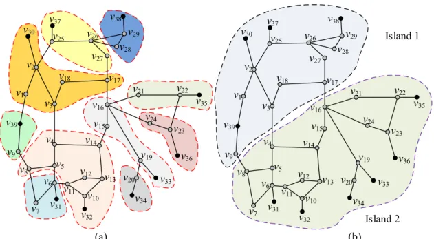
of the IEEE 39-bus system. The black and the grey dots are the generation- and the load-nodes, respectively. We explain the subgraphs shown in Fig. 1 in more detail in Section 4.1.
v38 v29 v28 v27 v26 v37 v25 v30 v2 v9 v39 v1 v13 v12 v10 v32 v11 v31 v6 v5 v7 v8 v16 v15 v14 v4 v18 v17 v3 v36 v23 v24 v21 v22 v35 v19 v33 v34 v20 Island 1 Island 2 v38 v29 v28 v27 v26 v37 v25 v30 v2 v9 v39 v1 v13 v12 v10 v32 v11 v31 v6 v5 v7 v8 v16 v15 v14 v4 v18 v17 v3 v36 v23 v24 v21 v22 v35 v19 v33 v34 v20 (a) (b)
Fig. 1. Results for the IEEE 39-bus system (a) Representation of the Voronoi diagrams in the graph (b) Islanding solution for the case r = 2.
2.1.2 Graph Laplacian Matrices
Laplacian matrices are used in graph theory to describe and study graphs [18]. There are two main types of Laplacian matrices: the unnormalised Laplacian matrix L and the normalised Laplacian matrix LN. These matrices are used in this paper to represent the active power flow in the branches of the system.
The unnormalised Laplacian matrix L (used in [13]) of G is the n n× matrix computed as follows [18]:
[ ]
if ; if and ; 0 otherwise. i ij ij ij d i j w i j e = ⎧ ⎪ =⎨− ≠ ∈ ⎪ ⎩ L E (2)where di is the weighted degree of the node vi, which is defined as the total weight of the edges connected to that node [18]: 1 n i ij j d w = =
∑
. (3)The matrix L can be written as L D W – = , where D is a diagonal matrix with nonzero entries di, and W is the weighted adjacencymatrix of G, i.e., the matrix whose ij-entry is wij.
The normalised Laplacian matrixof G is the n n× matrix −1 2 −1 2 =
N
[ ]
1 if ; if and ; otherwise. 0 ij i j ij ij i j w d d i j e ⎧ = ⎪ =⎨− ≠ ∈ ⎪ ⎩ N L E . (4)The matrix LN has the advantage of being scale-independent and, in particular, it allows the comparison of graphs with different weights [18-22].
2.1.3 Eigenvalues of the Laplacian Matrices
Spectral clustering uses r eigenvectors of either L or LN to provide geometric coordinates for the nodes
i
v ∈V in r-dimensional Euclidean spaceRr [18]. This so-called spectral embedding (see Fig. 2 for an example) is then used to cluster the data-points using a clustering algorithm for point clouds in Rr, such as
k-means [18]. We use the normalised Laplacian LN as a number of studies have shown that it offers superior performance compared to L on weighted networks [18-22]. Hence, we will use the eigenvectors
2
, , , r
1
ψ ψ K ψ , associated with the smallest r eigenvalues 0=ν1≤ν2≤L ≤νr of the matrix LN [18]. In our methodology, the value of r is the number of islands to be created. This value corresponds to the number of identified coherent groups of generators [4-13], as current practices (e.g., [23, 24]) suggest that the number of islands should be equal to the number of coherent groups obtained after the severe disturbance. Note that, nevertheless, the proposed methodology can determine an islanding solution for any given number of islands.
2.1.4 Spectral Embedding
Spectral embedding refers to a representation of G in Rr using the eigenvectors 2
, , , r
1
ψ ψ K ψ [18]. Ordering these eigenvectors as columns creates a matrix X∈Rn r× with rows x
i, i=1,2, ,K n. Then the vector xi represents the coordinates of the node vi∈V in r-dimensional Euclidean space Rr.
To improve the quality of the solution, the vectors xi must be normalised to have length one before applying any clustering technique [19, 22]. Thus, we define
: i i i = x y x , i=1,2, ,K n. (5)
The normalization (5) effectively projects the vectors xi to the unit (r–1)-dimensional sphere
{
}
1 such that 1
r r
i i
− = y ∈ y =
After computing the spectral embedding, the nodes vi∈V can be seen as data-points xi in Rr, or yi on
1
r−
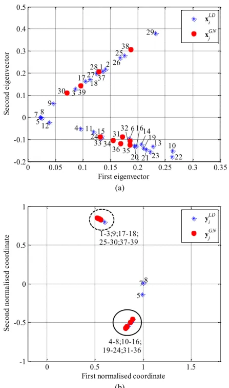
S . For example, we plot the vectors xi in Fig. 2(a) and the vectors yi in Fig. 2(b) for the spectral embedding of the IEEE 39-bus system when r=2.
0 0.05 0.1 0.15 0.2 0.25 0.3 0.35 -0.2 -0.1 0 0.1 0.2 0.3 0.4 0.5 1 2 3 4 5 6 7 8 9 10 11 12 13 14 15 16 17 18 19 20 2123 22 24 25 26 2728 29 30 3132 33 34 35 36 37 38 39 First eigenvector Se co nd e ig en ve ct or xiLD xjGN (a) 0 0.5 1 1.5 -1 -0.5 0 0.5 1 5 7 8 4-8;10-16; 19-24;31-36 1-3;9;17-18; 25-30;37-39
First normalised coordinate
Se co nd n or m al is ed c oo rd in at e yiLD yjGN (b)
Fig. 2. IEEE 39-bus system (a) 2-dimensional spectral embedding in Euclidean space R2 (b) Normalised vectors on the unit circle S1. The numbers on the diagram correspond to node numbers. The red dots and the
2.1.5 Representative Data-Points (Centroids)
We define XGN⊂X, and equivalently YGN ⊂Y, as the subset of data-points representing the m
generation-nodes GN i GN
v ∈V . Observe that XGN = YGN =m. We call these data-points centroids and denote
them by GN i
x and GN i
y in Rr and on Sr−1, respectively. We explain the function of these centroids in Section 3. The advantages of using centroids are to: (i) satisfy the generator coherency constraint, (ii) accelerate the identification of a solution, and (iii) reduce the memory usage by reducing the order of a similarity matrix. For an illustration, Fig. 2 shows the centroids as red dots and the remaining data-points (representing load-nodes) as blue asterisks.
2.1.6 Constrained Spectral Clustering
Constrained spectral clustering is an extension of spectral clustering which allows two main types of constraints, Must-Link (ML-) and Cannot-Link (CL-) constraints, to be used [20, 21]. A ML-constraint between two nodes indicates that the pair of nodes must be clustered together, and a CL-constraint specifies that the pair of nodes cannot be assigned to the same cluster. We will only consider ML-constraints in this paper, to exclude branches that must not be disconnected from the islanding solutions, as it is considered that CL-constraints have less relevance for practical implementations.
2.2 Intentional Controlled Islanding
Fig. 3 presents the general concept of ICI [25, 26], which is associated with the blackout progress [27]. Following a severe disturbance on a healthy system at t = tdist (known as initiating event), the slow degradation of the power system commonly takes place [1, 2]. Although Remedial Actions (RA) may be implemented to minimise the outage propagation, they may fail to restore the system to a secure state, either because they are not sufficient or they may just not be timely and effectively implemented by operators. This typically causes the system to enter the fast speed cascading outages, triggering the uncontrolled disconnection of system components and causing large-area blackouts [1, 2].
tdist
tcomp
timp Slow Degradation of Security Margin
tnec,isl Remedial Actions (RA)
Determine Necessity to Island
RA Fail Triggering Events Determine Islanding Solution Implement Islanding Post-Islanding Corrective Actions Stable Islanded Operation
Time (Not Scaled)
Fig. 3. Time-line showing the implementation of the methodology [26].
In this context, ICI aims to limit this fast speed cascading outages, by splitting the power system into several stable islands [28]. When the vulnerability analysis indicates the necessity to island at t = tnec,isl (when RA fail to minimise the impact of the initiating event), an islanding solution must be determined. To avoid any delay in the controlled islanding, it is important that the ICI method is computationally efficient to reduce the computational time [4]. Thus, after a short computational time, denoted as tcomp, an islanding solution must be determined to split the power system at the implementation time (timp), which must be before the system becomes uncontrollable. Post-islanding corrective actions (e.g., fast valving, load shedding, etc.) are expected to be undertaken, and stable islanded operation obtained [25].
2.2.1 Generator Coherency
Groups of generators can lose synchronism after a severe disturbance [8, 14, 29]. Each of these dynamically coherent groups of generators must be separated into different islands to help the transient stability of the system when determining an islanding solution [12]. Therefore, when the coherent groups of generators, denoted by VGN1, ,…VGNr, are identified after a severe disturbance, e.g., using approaches such as those described in [24, 29], our methodology will create islands such that each of these contains only coherent generators, as detailed below.
2.2.2 Quality of the Islanding Solution and Objective Function
Spectral clustering finds a cutset, that is, a subset of edges ES ⊂E whose removal splits the graph G into r disjoint subgraphs G1, ,…Gr [18]. Each subgraph corresponds to a node set V1, ,…Vr such that
1 r
V ∪…∪V =V and Vi∩Vj =∅ for all i≠j. An islanding solution consists in identifying an appropriate
We need a measure of the quality of an islanding solution (cutset) to evaluate the performance of the methodology. This can be done using the ratio between the cut and the volume of each subgraph (island).
The cut of an island represented by a node set Vk is the sum of the edge-weights between the nodes in Vk and the nodes not in Vk, i.e., the sum of the edge-weights linking Vk with its complement Vk [18]:
(
)
, , i k j k k k ij v V v V cut V V w ∈ ∈ =∑
. (6)The cut measures the connectivity of an island, and in our case it corresponds to the power flow disruption if the island Vk is disconnected from the rest of the system. We then make this quantity relative to the size of the island, in the following sense.
The volume of an island with node set Vk is the sum of the weighted-degrees of its nodes [18]:
( )
i k k i v V vol V d ∈ =∑
. (7)The volume of an island represents the internal power flow of the island plus the cross-boundary flow. We can then define the quality of an island Vk as one minus the cut relative to its size:
( )
(
)
( )
, 1 k k k k cut V V V vol V φ = − . (8)The quantity
φ
( )
Vk ranges from zero to one, and measures the connectivity of an island relative to itsvolume. For clustering purposes, the greater the value of
φ
( )
Vk , the better the island is considered to be [30].For example,
φ
( )
Vk =0.98represents a poorly connected island (its cross-boundary flow represents 2% of its total internal power flow), and hence a better candidate for islanding than a better connected island with( )
Vk 0.65φ
= . Hence a largeφ
( )
Vk represents an island with small power flow disruption and large internal power flow.We define the overall quality of an islanding solution as the worst (minimum) quality of the islands it creates, i.e.,
(
( )
)
1,2,...
min k
k= r φ V . Therefore, the clustering objective function is
( )
(
)
1,... 1,2,... max min rk r k V V = φ V , (9)that is, finding the r-partition maximising the worst (minimum) quality among its islands. We require, in addition, that each island contains only coherent generators
GNi i
that is, the ith island must contain the ith group of coherent generators. This overall formulation (9)-(10) reduces the possibility of overloading the branches in the created islands [14] and increases the probability that the generators in each island will remain in synchronism [12, 13].
Finally, we enable operators to exclude branches from the islanding solutions. To do so, we define a new subset EC ⊂E to represent branches that must not be disconnected, e.g., unavailable lines, lines that are
important for the stability of the islands or lines without synchro-check relays (these devices are vital during the restoration process [12]). Excluding these branches amounts to impose the condition EC ∩ES =∅, that is, to consider only partitions with cutsets ES not containing any excluded edges from EC.
With these new sets of constraints, the problem that we attempt to solve can be formulated as finding:
(
)
( )
1,..., 1,2,..., , min max r k k V V k r k cut V V vol V = ⎛ ⎞ ⎜ ⎟ ⎜ ⎟ ⎝ ⎠ subject to , and GNi i C S V ⊂V E ∩E =∅ (11)Note that this type of min-max optimization problems (11) on graphs are related to Laplacian eigenvalues, and this is the key connection between islanding with respect to minimal power flow disruption and spectral clustering [18]. Indeed, finding an optimal solution of (11) is in general NP-hard, and spectral clustering provides an efficient method of finding solutions of a relaxation of (11) [30], i.e., it gives approximate solutions in polynomial time (details can be found in [18], and elsewhere in the vast literature of spectral clustering). The approximate and the optimal solution can be related via the so-called Cheeger inequality [22], and this is one of the main theoretical justifications of the spectral clustering methodology [18]. We compare in Section 4.1 the quality of our solution with the quality of the optimal solution that is defined by the theoretical lower bounds of the Cheeger inequality [22].
3.
Proposed Islanding Methodology
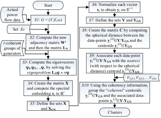
Our methodology aims to minimise the power flow disruption, while satisfying the generator coherency constraint and excluding the constrained branches from the islanding solution, i.e., our objective function is given by (11). As explained above, we use spectral clustering to approximate a solution in polynomial time (a few seconds in all our test cases) of this NP-hard problem. Fig. 4 shows the flowchart of the proposed methodology, which is based on the spectral clustering algorithm of [19]. We identify each step by an S
Step 1: Build the graph G using the power flow data computed at the moment of islanding (tnec,isl in Fig. 3).
Step2: Identify edges eij∈EC to be excluded from the cutset, and change their associated weight factor to the largest value in W (i.e., max (W)):
( )
for all eij∈EC,let 'wij =w'ji =max W . (12) The changes in (12) create a new weightedadjacency matrix W’, which is then used to compute the matrix
LN using (4).
Step 3: Compute the eigenvectors ψ ψ1, 2, ,K ψr of LN.
Step 4: Create the matrix X∈Rn r× , and compute the spectral embedding (see Fig. 2(a) for an example).
Step 5: Define the centroids GN i ∈ GN
x X in Rr (e.g., the red dots in Fig. 2(a)). The remaining data-points
\
LD
i ∈ GN
x X X (e.g., the blue-asterisks in Fig. 2(a)) represent the load-nodes ofG.
S1: G = (V,E,ω)
S3: Compute the eigenvectors
ψ1,ψ2,...,ψr by solving the eigenproblemLNψ = νψ
S4: Create the matrix X
and compute the spectral embedding xi in ℝr
S7: Define the sets Y and YGN S8: Create the matrix C by computing
the spherical distance between the data-points yiLD∈Y\YGN and the
centroids yjGN∈YGN
S9: Associate each data-point
yiLD∈Y\YGN with the nearest (with respect to the spherical distance) centroid yjGN∈YGN
r-coherent groups of generators
VGN1,VGN2,...,VGNr
S10: Using the coherency information, group the “coherent” centroids
yjGN∈YGN and the associated
data-points yiLD∈Y\YGN
Clusters Start
Set Ec
S2: Compute the new adjacency matrix W'
and then the matrix LN
Actual power flow data
S6: Normalize each vector
xi to obtain yi on𝕊r–1
S5: Define the sets X
and XGN
Fig. 4. Flowchart of the proposed methodology.
Step 6: Normalise the vectors xi∈X using (5) to compute the vectors yi which form the rows of a matrix n r×
∈
Y R . The vectors yi represent the nodes vi∈V as data-points on
1
r−
S (see Fig. 2(b) for an example).
Step 7: Define the data-points GN
i ∈ GN
Step 8: Compute the distances cij between the data-points LD \ i ∈ GN
y Y Y and the centroids GN
j ∈ GN
y Y (the
blue-asterisks and the red-dots in Fig. 2(b)). This creates a similarity matrix C:=
( )
cij . Note that the size ofC is reduced to
(
n m−)
×m, and the advantages of this reduction are discussed in Section 4.4.Step 9: Associate each data-point LD \ i ∈ GN
y Y Y with the nearest centroid GN
j ∈ GN
y Y . Mathematically, we
identify the minimum value in the ith row of C. Hence each load-node LD
i LD
v ∈V is grouped with one and only one generation-node GN
j GN
v ∈V . For example, we found in Fig. 2(b) that data-points 28 and 29 are
closer to the centroid marked as 38 than to any other centroid. Thus, the nodes v28, v29 are grouped with v38. When each load-node is associated with the closest generation-node, m disjoint subgraphs are obtained (see Fig. 1(a)). We define each of these subgraphs as the “domain of the generator for minimal power flow disruption”. This is a special case of a Voronoi diagram [31], which simply assigns each point to its closest centroid. In our methodology, each generator has a different domain and examples of generator domains are illustrated in Fig. 1(a) and explained in detail in Section 5.
Step 10: Create the final clusters (islands) by grouping the domains of the coherent generation-nodes. This ensures that the generator coherency constraint is satisfied. For example, the coherent groups of generators in the IEEE 39 are VGN1=
{
v v v v30, 37, 38, 39}
and VGN2={
v v v v v v31, 32, 33, 34, 35, 36}
(Fig. 5), thus we obtain the islands shown in Fig. 1(b).4.
Simulation Results
This section presents the simulation results. We use the dynamic models of the IEEE 39- and IEEE 118-bus test systems to demonstrate with time-domain simulations that the methodology can minimise the impact of cascading outages leading to blackouts. We also use a static model of a reduced Great Britain network with 815 buses to demonstrate the scalability of our methodology and to show that it is computationally more efficient and more accurate, in particular for large-scale networks, than the SCCI algorithm detailed in [13]. All time-domain simulations are performed in DIgSILENT PowerFactory [32], and the methodology has been implemented in MATLAB [33]. The times settings of the protective relays used in the simulations are carefully selected to show the desired oscillation mode, although, in practice, they may be shorter.
Additionally, instantaneous power flows are used for disconnecting overloaded lines. All times quoted are based upon simulations performed on a PC with 2.33 GHz double core CPU and 2 GB RAM.
4.1 Test Case I: IEEE 39-Bus System
We use the IEEE 39-bus system to illustrate our methodology in a small network. The data of this system and the controllers (Automatic Voltage Regulators and Power System Stabilisers only) can be found in [34].
Testing case description: We have increased the base load level by 25%, while maintaining the same power factor. This is done to stress the system and increase the likelihood of instability following a disturbance. This increment has been equally distributed among the generators G2–G7. The output power of the other generators remains the same. We then consider that at time t = 0 s, a three phase to ground solid fault occurs near bus 16 at line 16-17, and is cleared after local relays open the faulty line at t = 0.4 s. If no control action is undertaken, it can be observed in Fig. 5(a) that the system loses synchronism at about 2.8 s. Indeed, the software DIgSILENT PowerFactory [32] indicates out of step (pole slip) at t = 2.85 s. Then, due to the power oscillations and the line overloads caused by the disconnection of line 16-17, multiple lines are disconnected in cascade. Line 13-14 is disconnected at time t = 5.5 s. This then triggers the uncontrolled cascading outages of lines 4-5, 3-4, 5-8 and 6-7 at the times 6.2 s, 6.7 s, 7.1 s and 7.3 s, respectively. These cascading outages lead to the uncontrolled separation of the system into three islands, which are eventually affected by blackouts. Fig. 5(b) shows the frequency of the generators. As noticed, the system is partitioned into three groups, which are not balanced. Finally, Fig 5(c) illustrates that the voltage magnitudes at the system buses are considerably small, leading to a blackout of the system at about 7 s.
0 1 2 3 4 5 6 7 8 9 -4 -2 0 2 4 (a) Time, (s) δ (r ad.) G1; G8-G10 G2-G7 1.00 1.02 1.04 ω (p .u. )
0 1 2 3 4 5 6 7 8 9 0 0.5 1.0 (c) Time, (s) V (p .u. )
Fig. 5. Results for the IEEE 39-bus system without islanding (a) Generator rotor angle (b) Generator speed (c) Voltage magnitudes.
The loss of synchronism and the frequency of the generators are clear indicators that the system should be split [11]. Here we consider the necessity to partition the system at time t = 3 s. In practical implementations, this time depends on the vulnerability analysis performed following severe disturbances. We use our methodology to determine the most suitable islanding solution with respect to the actual power flow in the branches at t = 3 s. In the simulations presented for this test case, we assume that any transmission line can be included in the cutset, i.e., EC =∅. We exclude transformers from the solution.
Since two coherent groups are identified at t = 3 s, we define r=2 and consider the spectral embedding into R2 shown in Fig. 2(a). We then normalise the vectors xi in R2, i 1,2, ,39
= K , so they lie on the unit circle S1 shown in Fig. 2(b). We then compute the distance between the vectors LD \
i ∈ GN y Y Y (blue-asterisks) and the centroids GN
j ∈ GN
y Y (red-dots). We use these distances to build the similarity matrix C,
and each load-node LD
i LD
v ∈V is then grouped with the nearest generation-node vjGN ∈VGN. This preliminary grouping creates the “domain of each generator for minimal power flow disruption”, or Voronoi diagrams, shown in Fig. 1(a) in different background colours.
Then, as the identified coherent groups of generators shown in Fig. 5 are VGN1=
{
v v v v30, 37, 38, 39}
and{
}
2 31, 32, 33, 34, 35, 36 GN
V = v v v v v v , the clusters in Fig. 1(a) containing coherent generation-nodes are grouped
together to determine the islanding solution illustrated in Fig. 1(b). Table 1 shows the value of the cut (6), the volume (7) and the value of φ
( )
Vk (8) of each island obtained. We conclude that the quality of the islandingsolution (the minimum value of φ
( )
Vk from all of the islands) is 99.84%.Table 1: Results islanding the IEEE 39-bus system into two islands Cutset Island Cut Volume φ
( )
VkNo. (MW) (MW) (%)
8,9, 3,4, 16,17
e e e 1 12 7383 99.84
2 12 18605 99.94
This solution was obtained in approximately 1.5 ms (tcomp = 0.0015 s) and thus the corresponding corrective controlled strategy was undertaken at t = 3.0015 s. Fig. 6 presents the dynamic simulation results with islanding. We can see that the blackout has been successfully avoided, and two stable islands are created with frequency at t = 15 s between 0.989 pu and 1.035 pu, and voltages between 0.895 pu and 1.09 pu. Indeed, power flows computed in the post-islanding state demonstrate the feasibility of these results. Note that the machines are not equipped with governors. In practical implementations, control measures, such as fast valving, can be applied to decrease the frequency deviations.
We now compare the quality of the islanding solution determined by the proposed methodology, which was found in few milliseconds, with the optimal solution, which cannot be found in general in polynomial time [18]. The theoretical lower bound (defined by the eigenvalue ν2/2 of LN [22]) establishes that the quality of the optimal solution (defined by the Cheegerinequality, see [22] for more details) is bounded to 99.87%, whereas the quality of our approximation was 99.84%.
0 5 10 15 -4 -2 0 2 4 (a) Time, (s) δ (r ad.)
0 5 10 15 0.98 1.00 1.02 1.04 (b) Time, (s) ω (p .u. ) 0 5 10 15 0 0.5 1.0 (c) Time, (s) V (p .u. )
Fig. 6. Results for the IEEE 39-bus system with islanding (a) Generator rotor angle (b) Generator speed (c) Voltage magnitudes.
4.2 Test Case II: IEEE 118-Bus System
We now test the proposed methodology using the IEEE 118-bus system. The dynamic data of the generators can be found in [11], and they are selected according to the typical generator data in [35]. The generators have also been equipped with governors. The governor model is taken from the Standard Models library in DIgSILENT PowerFactory and is gov_TGOV1.BlkDef, a steam turbine governor [32]. We consider that any line can be included in the cutset ES, but transformers must be excluded from this.
Testing case description: We consider that at time t = 0 s, a three phase to ground fault occurs near bus 25 at line 23–25 and is cleared after local relays open the faulty line at 0.18 s. The swing trajectories obtained are shown in Fig. 7(a). It can be seen that within a short time after the fault is cleared, the generators are divided into two groups:
{
10,12,25,26,31}
and{
46,49,54,59,61,65,66,69,80,87,89,100,103,111}
. As it can be observed in Fig. 7(b)-(c), if the system is not split, the frequency of the generators in the first group considerably increases, the voltage magnitudes in major part of the network are significantly reduced, and, if no control actions are timely undertaken, the system quickly collapses.-0.5 0 0.5 1 1.5 2 -4 -2 0 2 4 (a) Time, (s) δ (r ad.) -0.5 0 0.5 1 1.5 2 1 1.1 1.2 (b) Time, (s) ω (p .u. ) -0.50 0 0.5 1 1.5 2 0.5 1 (c) Time, (s) V (p .u. )
Fig. 7. Results for the IEEE 118-bus system without islanding (a) Generator rotor angle (b) Generator speed (c) Voltage magnitudes.
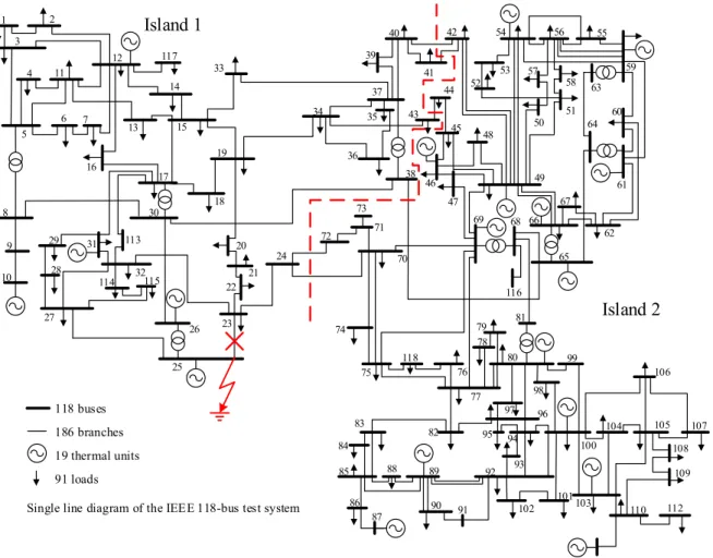
In this case, the necessity to split the system is considered to be at 0.38 s. The islanding solution found by our methodology is illustrated in Fig. 8. Table 2 summarises the results of each island; the quality of this islanding solution is 99.65%. This solution was found in approximately 8.1 ms, and hence the islanding was undertaken at 0.3881 s. Fig. 9 shows the dynamic response of the power system in the post-islanding state. As notice, these results indicate that our methodology can effectively prevent the blackout. We can also see that two islands are successfully created with frequencies between 0.9987 pu and 1.0111 pu. Similar to the previous case, we use the power flows in the post-islanding state to check the feasibility of these results. It is important to mention that this test network has not been equipped with voltage regulators; thus, the voltage magnitudes shown in Fig. 9(c) are expected to be higher in the scenario where these controllers are used.
1 2 3 4 117 33 12 11 5 6 7 13 14 15 19 18 17 30 113 16 8 9 10 29 27 32 114 26 25 23 22 21 20 31 35 34 36 73 72 24 74 75 83 84 85 86 88 89 82 90 91 87 95 94 93 92 102 101 112 111 110 103 109 108 107 105 106 104 100 99 81 79 96 80 78 76 77 118 70 71 116 68 69 38 41 37 43 45 48 46 47 39 40 42 54 52 53 56 59 55 58 51 60 64 61 49 67 66 62 65 63 50 115 44 57 98 97 28 118 buses 186 branches 19 thermal units 91 loads
Single line diagram of the IEEE 118-bus test system Island 1
Island 2
Fig. 8. Single line diagram of the IEEE 118-bus test system and proposed islanding solution.
Table 2: Results islanding the IEEE 118-bus system into two islands Island No. Cut (MW) Volume (MW)
( )
k V φ (%) 1 28 7961 99.65 2 28 10193 99.734.3 Test Case III: Reduced Great Britain Network
We finally test the proposed methodology using a realistically sized power system, a static model of a reduced Great Britain network with 815 buses. Specifically, we study splitting into r islands for r=2,3,4,5.
These static simulations aim to demonstrate the scalability of our methodology, and to compare it with an existing SCCI algorithm [35]. Table 3 shows the total power flow disruption and the quality of each islanding solution, i.e.,
(
( )
)
1,2,...
min k
0 5 10 15 -4 -2 0 2 4 (a) Time, (s) δ (r ad.) 0 5 10 15 0.98 1 1.02 1.04 1.06 (b) Time, (s) ω (p .u. ) 0 5 10 15 0 0.5 1 (c) Time, (s) V (p .u. )
Fig. 9. Results for the IEEE 118-bus system with islanding (a) Generator rotor angle (b) Generator speed (c) Voltage magnitudes.
Table 3. Results and comparison using the Great Britain network No. of
Islands
Proposed Methodology Existing SCCI Algorithm
Cut (MW) Quality (%) Cut (MW) Quality (%) 2 1869 98.79 1869 98.79 3 1895 98.72 2167 95.06 4 3332 94.73 4204 93.69 5 5333 96.95 6318 95.06
As noticed, the results using our methodology are as good (when r=2) or significantly better (when
3,4,5
r= ). It is important to note that our methodology improves the accuracy of the results (measured as the ratio between the total power flow disruption difference and the power flow disruption using the existing technique) in 12.6%, 20.7% and 15.6% for the cases with r = 3, 4 and 5, respectively.
4.4 Evaluating the Computational Efficiency of the Proposed Methodology
only once, even when multiple islands are to be created, which considerably accelerates the determination of an islanding solution, particularly when dealing with large-scale power systems, and potentially increases the quality of the islanding solution [18-22].
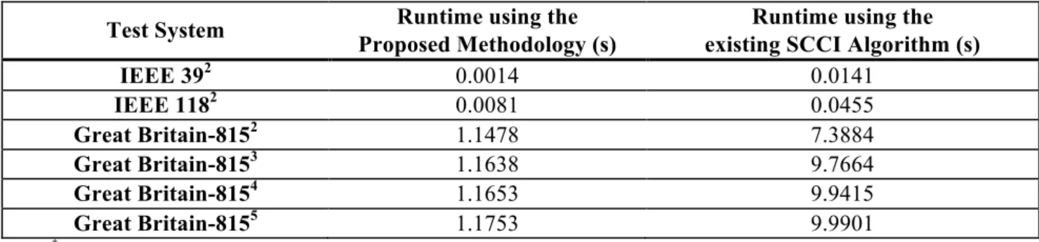
Table 4. Computational time using both the proposed methodology and the existing SCCI algorithm (average runtime over 1000 instances with the same loading condition)
Test System Runtime using the
Proposed Methodology (s)
Runtime using the existing SCCI Algorithm (s)
IEEE 392 0.0014 0.0141 IEEE 1182 0.0081 0.0455 Great Britain-8152 1.1478 7.3884 Great Britain-8153 1.1638 9.7664 Great Britain-8154 1.1653 9.9415 Great Britain-8155 1.1753 9.9901
*The superscript indicates the number of created islands
The runtime of our methodology is dominated by that of the eigendecomposition of a real symmetric n n× matrix. Therefore, the theoretical computational complexity of our methodology is approximately
O(n3) [21], although it can be reduced to O(n4/3) when utilising a sparse form of LN [15].
The key message is that our methodology is capable of determining an islanding solution in real-time even for large-scale power systems, as we can see in Table 4. In fact, our methodology reduces in a factor of approximately ten the computational time respect to the competing SCCI algorithm. Consequently, our methodology can meet the demand of real-time controlled islanding.
5.
Discussion
The proposed ICI methodology can effectively prevent cascading outages leading to large-area blackouts by islanding the bulk network across the lines with reduced power flow following a severe disturbance, i.e., it can find an islanding solution with minimal power flow disruption. Even though the new approach has significantly improved the voltages at all the system buses for the IEEE 39- and IEEE 118-bus test systems (see Figs. 6 and 9) compared to the uncontrolled separation, additional research is required to include voltage stability constraints in the formulation. This further improvement can help ensure that the power system will successfully operate after islanding actions are undertaken. Additionally, post-islanding analyses and simulations are required in practical implementations of the new approach to evaluate its behaviour in these new cases.
The proposed ICI methodology can determine islanding solutions for any given number of islands, while ensuring that each island contains only coherent generators. Even though this approach enhances the transient stability of the islands [12], it cannot consider the location of the fault that has caused the loss of synchronism between the coherent groups of generators. Hence, additional investigations to consider the fault location could further improve the applicability of the new approach.
In order to enhance the transient stability of the future islands, our approach has followed current practices, and has considered the generator coherency constraint in the formulation. However, further research is required to consider the true transient stability constraint. This remains an open, extensive and exciting area of research.
Finally, the proposed ICI methodology has considered that the number of islands to be created is equal to the number of coherent groups of generators. Although this follows current practices, e.g., [23, 24], it would be interesting to further investigate the applicability of the methodology for different number of islands. This is of particular interest as the number of coherent groups is not a necessarily unique solution [19] due to changes in system operating condition and network configuration, and this will have consequences for the islands obtained, and their quality.
6.
Conclusions
This paper proposes a novel methodology, based on constrained spectral clustering, that determines an islanding solution for minimal power flow disruption, while ensuring that each island contains only coherent generators. It also enables operators to constrain any branch to be excluded from the islanding solution. The proposed methodology uses the first r eigenvectors of a normalised Laplacian matrix associated with the graph that represents the power flow of the power system, and this approach improves the quality of the islanding solutions, compared to competing methods that use the unnormalised Laplacian matrix.
The new methodology has the key advantage that it solves the associated eigenproblem only once, even when multiple islands are to be created. As we avoid recursive bisection, the methodology considerably accelerates the determination of an islanding solution and simultaneously improves its quality. Furthermore, our methodology defines the vectors representing the generation-nodes as centroids on the unit sphere in Euclidean space, and computes, just once, the distance only between the vectors representing load-nodes and
the centroids. This reduces the order of the similarity matrix and avoids the use of iterative approaches. These two features also contribute accelerating the determination of an islanding solution.
The proposed methodology was tested and validated using dynamic models of the IEEE 39- and IEEE 118-bus test systems. Time-domain simulation results are used to demonstrate that our methodology can minimise the impact of cascading outages leading to blackouts. We have also presented static simulations on a reduced Great Britain network with 815 buses to demonstrate the scalability of our methodology, to show that it meets the real-time requirements of islanding methods even for large-scale power systems, and to compare it with a competing algorithm. These simulations show that our methodology can be used with practical power systems to determine, in a limited timeframe, a good islanding solution, i.e., a solution with small power flow disruption relative to the power in each island, and any given number of islands.
7.
Acknowledgements
The authors would like to thank all the anonymous reviewers for their many valuable suggestions during the reviewing process. The first and fifth authors would like to thank the Engineering and Physical Science Research Council (EPSRC) grants EP/E009735/1 in the U.K, and the Office of International Affairs and External Cooperation at the University of Costa Rica for their financial support. The second, third and fourth authors would like to acknowledge support by EPSRC grants EP/G059101/1 and EP/G060169/1.
8.
References
[1] G. Andersson, P. Donalek, R. Farmer, et al., "Causes of the 2003 major grid blackouts in North America and Europe, and recommended means to improve system dynamic performance," IEEE Transactions on Power Systems, vol. 20, no. 4, p. 19221928, 2005.
[2] P. Kundur and C. Taylor, "Blackout experiences and lessons, best practices for system dynamic performance, and the role of new technologies," IEEE Task Force Report2007.
[3] V.E. Henner, "A network separation scheme for emergency control," Int. J. Electr. Power Energy Syst.,
vol. 2, no. 2, pp. 109–114, Apr. 1980.
[4] M.M. Adibi, R.J. Kafka, S. Maram, and L.M. Mili, "On power system controlled separation," IEEE Transactions on Power Systems, vol. 21, no. 4, pp. 1894-1902, Nov. 2006.
[5] H. You, V. Vittal, and Z. Yang, "Self-healing in power systems: an approach using islanding and rate of frequency decline-based load shedding," IEEE Transactions on Power Systems, vol. 18, no. 1, pp. 174-181, Feb. 2003.
[6] K. Sun, D. Zheng, and Q. Lu, "Splitting strategies for islanding operation of large-scale power systems using OBDD-based methods," IEEE Transactions on Power Systems, vol. 18, no. 2, pp. 912-923, May 2003.
[7] Q. Zhao, D. Zheng, J. Ma, and Q. Lu, "A study of system splitting strategies for island operation of power system: A two-phase method based on OBDDs," IEEE Transactions on Power Systems, vol. 18, no. 4, pp. 1556-1565, Nov. 2003.
[8] H. You, V. Vittal, and X. Wang, "Slow coherency - Based islanding," IEEE Transactions on Power Systems, vol. 19, no. 1, pp. 483-491, Feb. 2004.
[9] G. Xu and V. Vittal, "Slow coherency based cutset determination algorithm for large power systems,"
IEEE Transactions on Power Systems, vol. 25, no. 2, pp. 877-884, May. 2010.
[10] C. Wang, B.Zhang, Z. Hao, et al., "A novel real-time searching method for power system splitting boundary," IEEE Transactions on Power Systems, vol. 25, no. 4, pp. 1902-1909 Nov. 2010.
[11] K. Sun, D. Zheng, and Q. Lu, "A simulation study of OBDD-based proper splitting strategies for power systems under consideration of transient stability," IEEE Transactions on Power Systems, vol. 20, no. 1, pp. 389-399, Feb. 2005.
[12] L. Hao, G.W. Rosenwald, J. Jung, and C.C. Liu, "Strategic power infrastructure defense," Proceedings of the IEEE, vol. 93, no. 5, pp. 918-933, May 2005.
[13] L. Ding, F. Gonzalez-Longatt, P. Wall, and V. Terzija, "Two-step spectral clustering controlled islanding algorithm," IEEE Transactions on Power Systems, vol. 28, no. 1, pp. 75-84, Feb. 2013.
[14] J. Machowski, J.W. Bialek, and J.R. Bumby, Power System Dynamics Stability and Control. West Sussex: John Wiley & Sons, 2008.
[15] A. Peiravi and R. Ildarabadi, "Comparison of computational requirements for spectral and kernel k-means bisection of power system," Australian J. of Basic and Applied Sciences, vol. 3, no.3, pp. 2366-2388, 2009.
[16] T. Leighton and S. Rao, "Multicommodity max-flow min-cut theorems and their use in designing approximation algorithms," Journal of the ACM, vol. vol. 46, no. 6, pp. 787-832, Nov. 1999.
[17] M.R. Garey and D.S. Johnson, Computers and Intractability: A Guide to the Theory of NP-Completeness. San Francisco, CA: Freeman, 1979.
[18] U. Von Luxburg, "A tutorial on spectral clustering," Statistics and Computing, vol. 17, no. 4, pp. 395-416, Dec. 2007.
[19] A.Y. Ng, M.I. Jordan, and Y. Weiss, "On spectral clustering: Analysis and an algorithm," Advances in Neural Information Processing Systems, vol. 2, pp. 849-856, 2002.
[20] X. Wang and I. Davidson, "Flexible constrained spectral clustering," in 16th ACM SIGKDD International Conference on Knowledge Discovery and Data Mining (KDD 2010), Washington DC, USA, 2010, pp. 563-572.
[21] X. Wang, B. Qian, and I. Davidson, "On constrained spectral clustering and its applications," Data Mining and Knowledge Discovery, pp. 1-29, Sep. 2012.
[22] J.R. Lee, S.O. Gharan, and L. Trevisan, "Multi-way spectral partitioning and higher-order Cheeger inequalities," in 44th symposium on Theory of Computing, 2012, pp. 1117-1130.
[23] R. Franco, C. Sena, G.N. Taranto, and A. Giusto, "Using synchrophasors for controlled islanding—A prospective application for the Uruguayan power system," IEEE Transactions on Power Systems, vol. 28, no. 2, pp. 2016-2024, May 2013.
[24] M.A.M. Ariff and B.C. Pal, "Coherency identification in interconnected power system — An independent component analysis approach," IEEE Transactions on Power Systems, vol. 28, no. 2, May 2013.
[25] V. Terzija, P. Wall, J. Quirós-Tortós, S. Norris, and J. Bialek, "Preventing cascading outages by intentional controlled islanding " in IEEE PES General Meeting, Vancouver, 2013.
[26] J. Quirós-Tortós, M. Panteli, V. Terzija, and P. Crossley, "On evaluating the performance of intentional controlled islanding schemes," in IEEE PES General Meeting, Vancouver, 2013, pp. 1-6.
[27] P. Pourbeik, P. Kundur, and C.W. Taylor, "The anatomy of a power grid blackout - Root causes and dynamics of recent major blackouts," IEEE Power & Energy Magazine, vol. 4, no. 5, pp. 22-29, Sept.-Oct. 2006.
[28] J. Quirós-Tortós and V. Terzija, "Controlled islanding strategy considering power system restoration constraints," in IEEE PES General Meeting, San Diego, 2012, pp. 1-8.
[29] C. Juarez, A.R. Messina, R. Castellanos, and G. Espinosa-Perez, "Characterization of Multi-Machine System Behavior using a Hierarchical Trajectory Cluster Analysis," IEEE Transactions on Power Systems, vol. 26, no. 3, pp. 972-981, Aug. 2011.
[30] R. Sánchez-García, M. Fennelly, S. Norris, et al., "Hierarchical clustering of power grids," IEEE Transactions on Power Systems, vol. in press, pp. 1-9, 2014.
[31] A. Okabe, B. Boots, K. Sugihara, and S.N. Chiu, Spatial Tessellations: Concepts and Applications of Voronoi Diagrams, 2nd ed. England: John Wiley & Sons, 2000.
[32] DIgSILENT PowerFactory, ed. Heinrich-Hertz-Straße, Germany. [33] MATLAB R2010a: Natick, Massachusetts: The MathWorks Inc., 2010.
[34] IEEE PES PSDPC SCS. (2013, Oct.). Power System Test Cases. Available: http://www.sel.eesc.usp.br/ieee/
[35] P.M. Anderson and A.A. Fouad, Power System Control and Stability, 2nd ed. New York: IEEE Press, 2003.
![Fig. 3. Time-line showing the implementation of the methodology [26].](https://thumb-us.123doks.com/thumbv2/123dok_us/663039.2579965/9.892.137.749.93.324/fig-time-line-showing-implementation-methodology.webp)