A splitting infrastructure for load balancing and
security in an MPLS network
Stefano Avallone, Vittorio Manetti, Marina Mariano and Simon Pietro Romano
COMICS Lab, Dipartimento di Informatica e SistemisticaUniversit`a di Napoli Federico II, Via Claudio 21, 80125 Napoli, Italy Email:{stavallo, vittorio.manetti, spromano}@unina.it, [email protected]
Abstract— Several multi-path routing algorithms have been recently proposed to achieve load balancing and increase security. However, the functionalities required to split traffic flows over multiple paths have not been standardized yet. Multi-Protocol Label Switching (MPLS) offers a suitable environment to imple-ment multi-path routing algorithms, as multiple parallel Label Switched Paths (LSPs) may be established to carry each a portion of a traffic flow. This paper focuses on a traffic splitting mechanism designed for MPLS networks. We propose a set of new operations to be performed by the edge routers and illustrate them with reference to a popular open source implementation of the MPLS stack. We implemented the new operations and give a demonstration of their functionality using an experimental testbed.
I. INTRODUCTION
Recently, several multi-path routing algorithms have been proposed aimed to both increase the security level in case of malicious attacks and to best utilize the network resources through load balancing. Such algorithms typically rely on the possibility to explicitly route flows, which is available, e.g., in MPLS networks. However, MPLS lacks mechanisms to split an incoming flow over multiple LSPs. Indeed, the IETF standard [1] provides that a forwarding equivalence class (FEC) may be associated with multiple outgoing labels, but does not specify how this association can be realized. In this paper we present an engineering approach to the solution of such a problem by implementing and evaluating a technique for per-packet load balancing in MPLS networks.
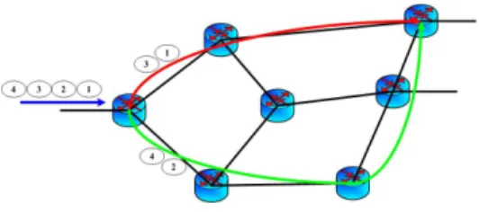
In order to fulfil the main goals we had in mind when designing our splitting technique, we have to deal with the two following major aspects: (i) the splitting criterion adopted; (ii) the specific features of the alternative paths to be selected. With reference to the first point, it looks clear that an ap-propriate splitting criterion needs to be implemented at the MPLS edge routers if we want to offer an adequate protection against potential security threats associated with the possibility that third parties intercept our traffic in some point of the network. Indeed, the idea of splitting traffic on a per-flow basis, while interesting from the load balancing perspective, would prove completely useless in the above depicted scenario. Hence, our approach relies on a per-packet splitting technique: packets arriving in sequence at an edge router are assigned to different paths inside the MPLS cloud (Fig. 1). Thanks to this choice, the information content that can be inferred by tampering with a single flow is almost negligible. A further
Fig. 1. Per-packet splitting
advantage of the proposed approach resides in the observation that all the information needed to implement the splitting procedure is confined at the edges of the MPLS cloud. The overall process is completely transparent to the core routers, which just keep on performing the standard label-swapping procedure. If our mechanism is put into place, a potential intruder would have to successfully accomplish all of the the following tasks: gain access to traffic flowing across every network path in the MPLS cloud; be aware of the specific splitting criterion adopted; be capable to identify the set of LSPs selected to carry a specific traffic aggregate from the ingress to the egress edges of the cloud.
We remark that the proposed mechanism can improve security but it is not an alternative to data encryption. Indeed, we believe it is possible to boost the security level of a network by using both encryption and a splitting technique like the one we are proposing in this paper.
Coming to the second aspect mentioned above, it looks clear that in an ideal situation all of the paths selected for a single flow that has been split at the ingress of the MPLS cloud should share the same properties in terms of parameters such as residual bandwidth, delay, packet loss, path length. The choice of paths characterized by significantly differing features definitely entails issues such as asymmetric balancing of the traffic load or out of order packet delivery.
The rest of the paper is structured as follows. Section II reviews some related work. Section III introduces the MPLS implementation in Linux which is the basis of our work. Section IV illustrates the splitting mechanism, while Section V details its implementation. Section VI presents the reordering mechanism. Section VII reviews the step to configure the splitting of a traffic aggregate in an MPLS network. Section VIII shows the experimental results, and section IX concludes our work.
II. RELATED WORK
Many research works have recently dealt with the issue of implementing load balancing techniques in MPLS networks. Our approach presents many facets which let it clearly depart from such works, most of which rely on load balancing in order to improve network resiliency to congestion conditions. MATE [2], e.g., proposes a model for traffic dispersion along auxiliary paths that have been selected to guarantee QoS requirements related to incoming traffic. The model presented in [3] works in a quite similar fashion. DYBLA (DYnamic Load Balancing Algorithm) [4] introduces the idea of splitting traffic among multiple paths right after having released the congested main path. In [5], a model is presented which maps a flow onto a path depending on the characteristics both of the path itself and of the traffic to be forwarded.
Our model definitely differs from the aforementioned ap-proaches aimed at tackling congestion issues, since it has been conceived at the outset as a means to improve the security level of the data sent across the splitting paths. With respect to this point, a related approach has recently been proposed in [6], which describes a mechanism based on traffic dispersion across multiple paths to solve the issue of potential eavesdropping. Some other related works have been designed with the goal of serving traffic classes with predefined features. In [7], a load balancing model for MPLS networks is presented with special reference to voice traffic support. Indeed, only few works propose load balancing solutions based on a per-packet approach. In [8] a path selection mechanism is devised, together with a per-packet splitting procedure based on a hash function applied to information carried inside network packets. In [9] a different per-packet splitting technique is presented. Once again, such mechanism aims to solve congestion issues in MPLS networks. The following related papers are all based on a per-flow load balancing approach. Except for [10], which proposes a load balancing mechanism for connectionless net-works whose effectiveness is assessed through Linux-based emulations, all other papers just rely on simulation studies. In [11] some simulation results are presented in order to compare the effectiveness of the application of load balancing techniques both with and without splitting.
Our primary goal is to perform real world experimentations aimed at demonstrating the effectiveness of the application of a per-packet splitting technique in an actual operational scenario. Based on this assumption, we delve into the details of the solution design to the point that the information needed to implement the splitting mechanism in a concrete platform is provided. In the light of the above consideration, we will not deal in this paper with issues such as the dynamic selection of the most suitable splitting paths or the automated configuration of the MPLS cloud. In some cases, we may assume that, by using paths sharing similar properties, packets keep on being forwarded in the right order even in the presence of splitting. Though, this assumption does not apply to all situations. Hence, we decided to implement a reordering mechanism at the MPLS level (i.e. at the egress of the MPLS cloud), so
to make splitting completely transparent to the upper layers of the protocol stack. Finally, we would also like to remark that our splitting technique does not put any limitation on the number of alternative paths that can be chosen to forward a single traffic aggregate entering the MPLS network.
III. MPLS-LINUX
The splitting technique we propose has been actually im-plemented by modifying the code developed within the mpls-linux project (http://sourceforge.net/projects/mpls-mpls-linux). This project provides a patch for the latest Linux kernel series (2.6.x) to add a full functional MPLS stack. A userspace utility is also provided to manually configure label switched paths. To this end, a set of instructions have been defined as follows:
push : adds an MPLS header to the packet with a specified label;
set : sends a packet down to the data link layer, thus causing it to be transmitted to the next hop router;
pop : removes an MPLS header from the packet;
fwd : causes a packet to be processed according to the instructions of a specified NHLFE entry, as will be explained shortly;
dlv : sends a packet to the IP stack for further processing; The mpls-linux patch introduces into the kernel the tables MPLS uses to forward data, as defined in [1]:
• FTN (FEC To NHLFE) The FTN table is made of a number of entries, each of which refers to a particular Forwarding Equivalence Class (FEC). The FTN is looked up when forwarding an unlabeled packet. Each entry contains a fwd instruction pointing to an NHLFE entry describing how to process packets belonging to that FEC.
• ILM (Incoming Label Map)The ILM table is looked up when forwarding labeled packets, i.e. packets containing an MPLS header. The entries of the ILM table are indexed by a key. Each entry of the ILM contains afwdinstruction pointing to an NHLFE entry describing how to process packets matching that key.
• NHLFE (Next Hop Label Forwarding Entry) An entry
of the NHLFE table is pointed to by an entry of the FTN, an entry of the ILM or another entry of the NHLFE and describes how to process a packet. Each entry of the NHLFE table is indexed by a key, too. However, here the key value is not related to any label and is set from a counter.
To illustrate how these tables are used in forwarding packets, we look at the operation performed by different routers in an MPLS network:
• Ingress LER (Label Edge Router) An ingress LER re-ceives unlabeled packets, adds an MPLS header and makes them continue their travel along an appropriate LSP. The first step is thus to classify each packet into a forwarding equivalence class (FEC) and look the FEC up in the FTN table. As a result, we obtain a key to access the entry of the NHLFE table which specifies the label
Fig. 2. Reordering packets
to be inserted into the MPLS header. Then, the packet is sent to the next-hop router.
• LSR (Label Switching Router) An LSR receives labeled packets, swaps the label and sends them to another LSR. This label swapping requires an access firstly in the ILM and subsequently in the NHLFE.
• Egress LER An egress LER receives labeled packets, removes the MPLS header and pass them on to the IP layer. The instructions sequence (pop - dlv) nedded to implements these tasks, is in an ILM entry.
IV. REORDERING PACKETS
Splitting the packets belonging to a flow over multiple paths may cause the packets to arrive at the egress LER out of order. It is known that such event cannot happen if all the packets are sent along the same LSP. Since the ordered delivery of packets is a desirable feature, we provide a reordering mechanism in order to emulate the behavior of an MPLS network with no splitting capabilities. To allow the egress LER to correctly reorder packets, the ingress LER has to put some extra information into the packets. We underline that the packet reordering can complement our splitting technique, but it is not mandatory. The reordering mechanism clearly imposes a non-negligible overhead on the ingress and egress LERs. However, it may prevent delays due to TCP reconstructing the original data flow. A performance evaluation of our reordering mechanism is presented in Section VIII.
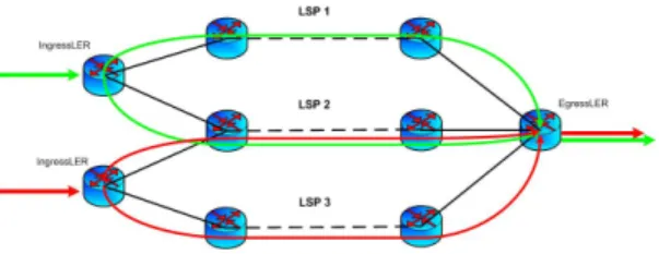
The MPLS label stacking capability can be exploited to carry some extra information. Indeed, the ingress LER can insert an additional MPLS header containing such information. At every hop, only the outer MPLS label is swapped and processed by the forwarding process. The inner label is carried unmodified till the egress LER where it is appropriately processed. To allow for the reordering of packets at the egress LER, the most straightforward solution relies on a counter whose value is incremented and attached to a packet when it crosses the splitter ingress node. The edge routers responsible for the reordering procedure interpret such value as a sequence number and are thus able to reconstruct the correct sequence of packets representing the original traffic. However, the adoption of a sequence number to be associated with all flows entering the MPLS network through the same ingress LER does not work in case the splitting paths can be shared. Let us consider the case where two flows belonging to different equivalence classes share a common splitting path (Fig. 2). The core LSRs falling along the shared path just
Fig. 3. A “splitting” MPLS header
perform standard label swapping operations, hence they do not elaborate splitting information contained inside the packet. If the above mentioned flows also have the final destination in common, then the egress LER must be able to associate each packet with the particular traffic aggregate to which it belongs. To allow for a correct reassembly of the flows, we need to introduce a novel parameter, called splitting-id, used to uniquely identify traffic belonging to a well defined FEC. A splitting-id uniquely identifies a traffic aggregate whose packets would be forwarded, in the absence of splitting, along the same path. Thus, in case reordering must be performed at the egress LER, every single packet has to carry both the sequence number and the splitting-id. We propose to encode such information in an additional (inner) MPLS header in the following way (Fig. 3):
• Label : sequence-number;
• EXP (Experimental Use): a selected value (e.g., 111) is
used to identify the splitting header;
• S (Stack): must be zero, as the splitting header must be at the bottom of the stack;
• TTL (Time To Live): contains the splitting-id, hence it does not have to be decremented at each hop.
In the following sections we detail the implementation of the splitting technique. Since the core routers perform their normal operation, we focus on the packet processing at the ingress and egress LERs.
V. PROCESSING AT THE INGRESSLER
The splitting mechanism we propose is based on a specific feature of the MPLS protocol, namely the possibility to associate a single FEC (Forwarding Equivalence Class) with multiple NHLFEs (Next Hop Label Forwarding Entry). A FEC identifies a class of flows asking for the same treatment in terms of forwarding: flows belonging to the same FEC are actually considered as a single entity in the MPLS cloud. Associating a FEC with a single NHLFE entry is equivalent to impose that packets belonging to the same equivalence class will be routed along the same LSP. Clearly, the possibility to associate a single FEC with multiple entries in the NHLFE table can be seen as a chance to manage flows on a per-packet basis, since different packets of the flow can be forwarded along different LSPs (Label Switched Path). Thus, providing a means to associate a FEC with multiple NHLFE entries is fundamental to make the splitting possible. The splitting mechanism thus necessitates the following functionalities:
• possibility to associate a single FEC with multiple
• inserting a sequence number and a splitting-id in the MPLS header in case an ordered delivery at the egress LER is required;
• forwarding of packets belonging to the same FEC to different LSPs.
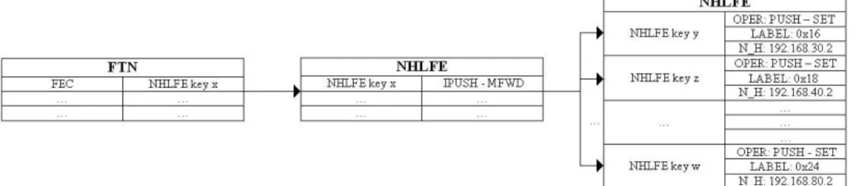
We propose to perform such an operation as illustrated in Fig. 4. The basic concept is quite simple: with respect to the common procedure performed in an ingress LER (see Section III), here we introduce an intermediate step consisting of the processing of an additional NHLFE entry. The FTN entry corresponding to the FEC of a given packet still points to an entry of the NHLFE. However, such an entry contains the special instructions we added and in turn points to a set of NHLFE entries. These last entries actually contain the push and set instructions to add an MPLS header and send the packet to the next hop. The new instructions to be inserted into the intermediate NHLFE entry areipush(increment and push) and mfwd(multipleforward). The first instruction is in charge of managing the parameters needed to implement the reordering mechanism, so it present only if needed. Theipush instruction has to perform two tasks: (i) recognition of the flow the packet belongs to, and (ii) update of the sequence number. Then, a splitting MPLS header (as shown in Fig. 3) is added to the stack of headers. Themfwdinstruction actually splits a flow by associating the intermediate NHLFE entry with other NHLFE entries. According to the adopted splitting policy, different NHLFE entries are selected for different packets, thus splitting the flow over multiple LSPs. An ingress LER splitting a flow over multiple LSPs performs the following operations: 1) The FEC the packet belongs to is used to access the FTN table in order to determine the key of the intermediate NHLFE entry;
2) In case we want to emulate the transmission along a single LSP, an ipush instruction is present in the intermediate NHLFE entry and it must be processed. As a consequence, a splitting MPLS header is added. In any case, the intermediate NHLFE entry contains an mfwd instruction which bounds the current FEC to a set of NHLFE entries (each corresponding to a different LSP). For each packet to be forwarded, one NHLFE entry in such set is selected based on the splitting policy (i.e., round robin);
3) The instructions contained in the selected NHLFE entry are processed. These includes adding a swapping MPLS header and sending the packet to the next hop.
The ipush instruction is quite similar to push, so it has been possible to reuse some code. Parameters required by these instructions are provided by an user level tool, the ‘mpls’ utility, which we needed to modify as well. This tool (available in the iproute package) provides instructions for the configuration of the MPLS tables entries, and hence of static LSPs. We have modified this tool in order to provide a splitting paths configuration mechanism. We remark that at the time of this writing no mechanisms are available to build and to destroy splitting paths in a dynamic way. In the near future,
we have in mind to work on the design and implementation of an automated policy-based configuration tool capable to carry out configuration of the MPLS cloud.
VI. PROCESSING AT THEEGRESSLER
In case a flow is split and the packet reordering is not needed, the egress LER must perform no additional operation. This section describes the configuration of the egress LER in case the ordered delivery of packets is required. To design-ing such mechanism, we introduced brand new functionality specifically conceived for the splitting/ reordering procedure.
Coming to the details, we impose that all packets associated with the same FEC (and thus characterized by the same splitting-id), once at the egress LER are forwarded to the same entry in the ILM (Incoming Label Map). Such entry contains the sequence of instructions needed to correctly reconstruct the original flow. Given the above constraint of using at the egress LER special instructions for packets belonging to flows that have been split, it looks clear that upon configuration of the MPLS cloud special entries must be added to edge routers tables. Such tables will then contain both standard label-swapping entries and experimental splitting entries.
The management of packet reordering in the described solution is based on the new functionality offered by MPLS layer in version 1.946 and later, including the mpls protocol driver mpls4. This module works between MPLS layer and IP layer, in particular representing the entry point to IPv4 layer. In the solution, the reordering mechanism has been put at this level, making the reordering mechanism transparent to all users. Moreover it uses the efficient and general methods of Linux system to manage data packets and manipulate them. Making the reordering mechanism transparent is possible by using the usually instructions related to an ILM entry: if a packet arrives with several MPLS labels, all of them are looked up step by step. Each label hooks an ILM entry and the corresponding instructions are executed. At to bottom of the stack, adlvinstruction is executed and the packet is sent to the upper layer. Indeed, the delivery instruction uses the central structure of network implementation, the so-called socket buffer, which represents a packet during its entire processing lifetime in the kernel. In the socket buffer they are defined hooks dedicated to manage the flow control requiring their access to mpls4 module (field skb→dst→output is a pointer to mpls local delivery), matching to dst entry of latest ILM entry. With few modifications to the function mpls opcode peek it is possible to pass data that are required to protocol driver to reorder packets. This information has been coded, respectively, inside the TTL, LABEL and EXP fields, and they are passed inside control-buffer field of socket buffer, in a similar way to MPLS layer and IP layer. In current design, the only action performed by mpls local delivery is returning the control to IP layer, to process the packets to be delivered locally. If the reorder is required, that is the experimental bits are setted up to111, the function mpls local deliver() passes IP packets to mpls reorder(). The packets are then managed in a packet-cache, until the packets arrive in a right order, so that all the
Fig. 4. Splitting technique
packets stored in the list can be delivered to the local machine. The packet-cache consists of a table hashed by Splitting-id and refer to an ip-queue structures. Each of these ip-queue structures store the packets waiting the right packet in the sequence. The individual socket buffers related to the same flow are linked in a list. All packets of a flow must to be ordered in the same sequence as they occur in the original flow. If an error occurred and the maximum wait time for the packet has expired, all the packets will be discarded.
VII. CONFIGURING THEMPLSCLOUD FOR SPLITTING
We summarize in the following the sequence of actions to be performed in order to configure the nodes of an MPLS cloud with splitting capabilities.
1) The FEC of the traffic aggregate we intend to split must be identified. A traffic aggregate is composed of a set of distinct flows having the same pair ingress LER/egress LER in common. If the packet reordering is needed, the traffic aggregate must be assigned a splitting id; 2) A set of LSPs between the ingress LER and the egress
LER are to be selected. The traffic aggregate will be splitted among the selected LSPs;
3) The MPLS tables of the nodes along the selected LSPs must be configured accordingly:
ILER: For each LSP, an NHLFE entry containing the push and set instructions is to be added. The key associated with these entries must be passed as parameters of the mfwd instruction present in the intermediate NHLFE entry. This last entry is pointed to by the entry of the FTN associated with the FEC of the traffic aggre-gate. In case the packet reordering is required, an ipush instruction must precede the mfwd instruction in order to add the splitting header. LSR : No particular operation is required on the core nodes. They are only required to perform the label swapping mechanism.
ELER: In case the packet reordering is required, we need to configure an ILM entry containing the following instructions:pop,reorder,dlv. VIII. EXPERIMENTAL RESULTS
In this section we present the results of some experiments conducted in a real testbed to show the effectiveness of our
Fig. 5. Performance evalution
approach. We focus our attention on the splitter ingress node. The main goal is to prove that the splitting mechanism causes a lower overhead and consequently a lower usage of computa-tional and storage resources when the reordering mechanism is disabled. We present a comparison between the classical label-switching mechanism on a single LSP and the splitting mechanism on several splitting paths, both with and without the reordering mechanism. The trials are carried out on a real testbed consisting of eight nodes equipped with a Pentium 4 Xeon processor. The Linux-MPLS patch (version 1.950) enhanced with our modifications was applied to all the nodes. In order to perform these experiments, we have selected a monitor (Oprofile) for evaluating the computational resources used by both user-level and kernel-level functionalities. This monitor produces a report showing the number of CPU cycles each function uses (in terms of percentage, related to the measurement interval). The experiments consist in configuring the LSPs along which the packets are forwarded, generating UDP traffic (by using the D-ITG traffic generator) on the Ingress LER (splitter node), and evaluating the computational load on the splitter node (by using the Oprofile monitor). We compare the performance of three mechanism: label-switching on a single LSP, splitting over 7 LSPs with and without reordering. Tests are made using 8, 12, and 16 flows forwarded across the MPLS cloud.
The table shows the cost of every single function/instruction of the MPLS stack for each of the three configurations under test and for the three scenarios we considered (8, 12 and 16 flows). Such a cost refers to the ratio (multiplied by 100) of the number of CPU cycles required to execute every single function to the number of CPU cycles required to
TABLE I
COST FOR THE DIFFERENT FUNCTIONS
8 FLOWS 12 FLOWS 16 FLOWS
label-switching splitting splitting label-switching splitting splitting label-switching splitting splitting function w reord w/o reord w reord w/o reord w reord w/o reord
0.00260 0.00590 0.00370 0,01390 0,02510 0,01960 0,01100 0,02060 0,01370 mpls output2 0,00190 0,00290 0,00180 0,00730 0,00970 0,00700 0,00490 0,00910 0,00460 mpls set nexthop2 0,00200 0,00210 0,00170 0,00910 0,01030 0,00780 0,00710 0,00850 0,00580 mpls send 0,00190 0,00170 0,00150 0,00970 0,01320 0,00920 0,00720 0,00970 0,00590 mpls push 0,00110 0,00140 0,00100 0,00740 0,00730 0,00650 0,00560 0,00520 0,00450 mpls output 0,00110 0,00130 0,00120 0,00560 0,00620 0,00600 0,00460 0,00490 0,00400 mpls out op set 0,00073 0,00110 0,00071 0,00410 0,00590 0,00410 0,00310 0,00500 0,00270 mpls output shim 0,00032 0,00060 0,00049 0,00240 0,00330 0,00220 0,00170 0,00250 0,00140 mpls p f by ethtype 0,00048 0,00055 0,00067 0,00250 0,00270 0,00190 0,00170 0,00230 0,00140 ipt mpls 0,00030 0,00015 0,00030 0,00190 0,00170 0,00140 0,00110 0,00089 0,00075 mpls op push 0,00003 0,00014 0,00003 0,00008 0,00048 0,00014 0,00013 0,00024 0,00006 mpls4 get ttl 0 0,00215 0,00144 0 0,00940 0,00910 0 0,00940 0,00910 mpls op mfwd 0 0,00260 0 0 0,01200 0 0 0,01020 0 mpls op ipush 0,01246 0,02259 0,01454 0,06398 0,10728 0,07494 0,04813 0,08613 0,05171 TOT
execute all the functions in the sample interval. The set of MPLS functions clearly comprises those we introduced for the splitting mechanism (mpls op mfwd and mpls op ipush). Fig. 5 shows for every scenario and every configuration the total cost, i.e., the sum of the costs of all the functions, which is also reported in the last row of the table.
We can draw that the splitting mechanism involves a very low overhead with respect to the classical label-switching mechanism, and, as we could expect, the reordering mech-anism requires some computational load. The results indicate that the total cost shows a very similar behavior for all the three configurations. It is worth to note that, given the approach used to determine the computational load of each function, it is not appropriate to compare the numeric values for the three scenarios. It is clear indeed that each of such scenarios is characterized by a different load of the CPU of the splitter node, relating to which we compute the cost of the MPLS functions. Also, the CPU load due to the traffic generator varies with the number of flows involved.
The table also shows that the mpls output2 function (which depends on the number of times we access the NHLFE table) exhibits a similar behavior for all the three scenarios. The splitting mechanism causes an increase in the cost of such a function, especially if we use the reordering mechanism, due to the increased number of times we access the NHLFE table of the ingress LER when the splitting is enabled.
IX. CONCLUSION AND FUTURE WORK
In this paper we presented an approach to improve network security and resource utilization in MPLS networks. The mechanism we proposed is based on the idea of splitting flows on a per-packet basis at the ingress of an MPLS cloud, while reassembling them in the right sequence before they leave the egress LER. Our main contribution resides in having devised a technology-independent solution which relies on the intro-duction of some new MPLS functions. We demonstrated such functions by implementing them in the MPLS stack for Linux. Our future work will be organized along three main directions:
(i) complete and refine the prototype implementation of the reordering mechanism; (ii) perform a thorough experimental campaign aimed at assessing the validity of our approach; (iii) work on the management part by providing an automated policy-based configuration tool.
ACKNOWLEDGMENT
Research outlined in this paper has been partially supported by the European Union under the ONELAB Project FP6-034819 and by the Italian Ministry for Education, University and Research (MIUR) in the framework of the NADIR Project (PRIN Program).
REFERENCES
[1] E. Rosen, A. Viswanathan, and R. Callon, “Multiprotocol Label Switch-ing Architecture,” IETF,” RFC 3031, January 2001.
[2] A. Elwalid, C. Jin, S. Low, and I. Widjaja, “MATE: MPLS Adaptive Traffic Engineering,” inProc. of IEEE INFOCOM 2001, vol. 3, 2001, pp. 1300–1309.
[3] M. Heusse and A. Gravey, “A Routing and Resource Preservation Strategy for Traffic Engineering in Communication Networks,” inProc. of 18th ITC, September 2003.
[4] E. Salvadori and R. Battiti, “A load balancing scheme for congestion control in MPLS networks,” inProc. of ISCC 2003, July 2003, pp. 951– 956.
[5] B. Cui, Z. Yang, and W. Ding, “A Load Balancing Alghorithm Sup-portino QoS for Traffic Engineering in MPLS Networks,” in Proc. of The Fourth International Conference on Computer and Information Technology (CIT’04), 2004.
[6] H. Zlatokrilov and H. Levy, “Session Privacy Enhancement by Traffic Dispersion,” inProc. of IEEE INFOCOM 2006, April 2006.
[7] B. Yang, C. Casetti, and M. Gerla, “Stateless Load Balancing over Multi-ple MPLS Paths,” available athttp://gregorio.stanford.edu. [8] X. Hesselbach, R. Fabregat, B. Baran, Y. Doloso, F. Solano, and M. Huerta, “Hashing based traffic partitioning in a multicast-multipath MPLS network model,” inProc. of IFIP/ACM Latin America Networking Conference 2005 (LANC 2005), 2005.
[9] A. Dana, A. K. Zadeh, and M. J. Akhlaghinia, “Performance Evaluation of a Load Scheme in MPLS Network,” in Proc. of Communication Systems and Applications 2005, 2005.
[10] H. T. Kaur and S. Kalyanaraman, “A Connectionless Approach to Intra-and Inter-Domain Traffic Engineering,” inProc. of 2nd New York Metro Area Networking Workshop, September 2002.
[11] J. Wang, “Load Balancing in Hop-by-Hop Routing with and without traffic splitting,” University of Illinois at Urbana-Champaign, Tech. Rep., October 2003.