Abstract—This paper presents the mechatronic design of a
robotic hand for prosthetic applications. The main characteristic of this robotic hand is its biologically-inspired parallel actuation system, which is based on the behavior/strength space of the Flexor Digitorum Profundus (FDP) and the Flexor Digitorum Superficialis (FDS) muscles. The design separates the strength space of the FDS and FDP muscles into a lighter strength region where finer manipulation and general approach tasks are executed, and a higher strength region where the more robust grasps are achieved. Two parallel actuator types and kinematic structures are designed to complement the requirements of both strength space regions. This unique structure is intended to be driven by electromyographical (EMG) signals captured at the surface of the skin. The direct relation between signal and actuation system lends itself well to interpreting the EMG signals from the FDP and FDS muscles into effective task execution, with the goal of helping the user to achieve a good approximation of the full capabilities associated with the human hand, without compromising strength, dexterity, appearance, or weight; which are common issues associated with prosthetic hands. The designed finger’s capability of having a strength space similar to that of the FDS and FDP muscles is validated via direct inputs from a power supply and then via a controller using an actual EMG signal input from the human forearm. The controller is a simple feed forward system at this point in the research but provides the appropriate framework to integrate more elaborate control schemes and EMG signal conditioning as this portion of the research area matures.
Keywords – Prosthetics, Parallel Actuation Structure, Robotics, Hand, FDS and FDP Muscles
I. INTRODUCTION
HERE Have been many different approaches taken in the development of an effective prosthetic hand. These varying strategies often find themselves focusing on one of the following categories: implementing a new actuator type [11-16], developing a more effective kinematic structure [18,23,34], integrating effective compliance [18,23-25],
Manuscript received May 24, 2010. this research was performed under an award/contract from Telemedicine Advanced Technology Research Center (TATRC), of the U.S. Army Medical Research and Materiel Command (USAMRMC) of the U.S. Department of Defense.
A. L. Crawford was a Ph.D. student at Idaho State University, Pocatello, ID 83209 (e-mail: [email protected])
J. Molitor is a Masters student at Idaho State University, Pocatello, ID 83209 (e-mail: [email protected])
M. A. Perez-Gracia is an assistant professor at Idaho State University, Pocatello, ID 83209 and is currently at Institut de Robotica i Informatica Industrial (UPC/CSIC), Barcelona, Spain (e-mail: [email protected])
generating effective control strategies [25-31], and interpreting/conditioning input signals [25]. Advances in these areas have resulted in robotic hands that perform many tasks with a high similarity to that of the human hand, such as the DLR hand [33], I-Limb hand [11], Shadow hand [12], and Fluidhand [32] to name a few. However, a prosthetic hand that is nimble, quick, strong, lightweight, quiet, and efficient [1] has yet to be achieved.
The primary reason for the current state of prosthetic hands has been the complexity associated with the human hand as a result of its multiple bones and joints (Fig 1). This is further compounded by the fact that the human hand as a functioning unit does not just embody the palm and its digits but also the wrist, forearm muscles, nervous system, and the body’s energy generation system. As a result, the entire prosthetic hand actuation structure (inputs, power, strength, kinematics, etc.) must fit in a significantly reduced volume compared to the human hand that it is replacing.
To address some of the challenges described above, this research implements a unique perspective of the FDS and FDP muscles’ strength space in the human forearm and proposes a novel design and parallel actuation structure that complements this perspective. The goal is to create a direct relation between the forearm’s EMG signals and the actuation system, in order to help the user achieve a good approximation of the full capabilities associated with the human hand in a compact design.
Fig 1: Joint/Bone composition of human hand [2]
Design of a Robotic Hand and Simple EMG Input Controller with a
Biologically-Inspired Parallel Actuation System for Prosthetic
Applications
Dr. Anthony L. Crawford, Member, IEEE, Jeffrey Molitor, Member, IEEE, Dr. Alba Perez-Gracia Member, IEEE, Dr. Steve C. Chiu, Member, IEEE
Sections 2 and 3 of this paper describe the FDS and FDP muscles’ strength space, how it relates to the human hand’s capabilities, as well as the actuators and actuation structures of current prosthetic/robotic hands. Sections 4 and 5 will provide a description of the mechanical design and testing results that justify the design’s ability to execute the strength space perspective developed in this paper. The paper will finally present conclusions associated with the testing results and an identification of future work. The actuation structure’s mechanical design presented here is an expansion of the content being published at the ASME IDETC 2010 conference with the inclusion of friction in the force calculations, implementation of the mechatronics, and the EMG inputs being an expansion of that presented research.
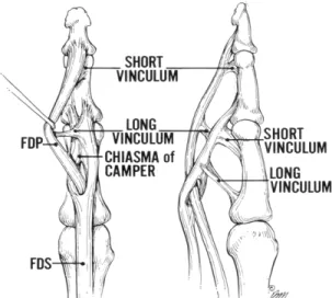
The FDS and FDP muscles are the primary flexor muscles in the human finger and are primarily opposed by the extensor digitorum (ED) muscle. As shown in Fig 2. The FDP muscle is attached to the distal phalanx and is capable of full hand closure; it is considered to be the more active of both finger flexion muscles. The FDS muscle is attached to the middle phalanx and its full capacity is primarily achieved when activation of the DIP joint is not required or when full hand closure tasks require additional strength [3].
The strength space of the FDS and FDP muscles is shown in Fig 3. The figure demonstrates the normalized maximal force exertion of the FDS and FDP muscles (y-axes) during maximum force execution of the hand (x-(y-axes). The FDP muscle is shown to reach its maximal force execution (120N [5]) at approximately 35% of the total flexural effort; however, the FDS muscle continues to exert force until it reaches its maximal force execution (240 N [5]) at about 100% of the total flexural effort. The FDS and FDP behavior can be attributed to the learned neurological activation of these muscles [6] as well as the finger’s associated kinematic structure.
Fig 2: Graphic of FDS and FDP muscle in finger [4]
Fig 3: Strength space of FDS and FDP muscles (x-axis: normalized postion of hand from open (0) to closed (1), y-axis: normalized force)[7] The FDS and FDP strength space comprises the strength requirements for all the tasks that a hand must execute [8][9]. In general, most everyday tasks don’t require extensive force but do require a certain amount of dexterity. For manipulation or approaching an object, the finger can employ both the FDS and FDP muscles to nimbly accommodate various shapes and execute both general and complex movement paths. Fig 3 shows that the FDS and FDP muscles are both active for activities below 35% of the maximum force capacity of the hand and are most likely employed during manipulation/object approaching movements.
Gripping tasks generally require less dexterity and more strength than manipulation and general object approach. The size and weight of the object as well as the characteristics of the grasp (e.g. friction between pads or force closure) determines how much force is required from the finger’s strength space shown in Fig 3. It is to be noted that the actual act of the grip also generally requires much less complex finger motion than that of manipulation. Based on these observations, we divided the FDS and FDP strength space into the regions shown in Fig 4. In Fig 4 region 1 is populated by the more frequent dexterous tasks and region 2 is populated by the less frequent and more strength-based tasks.
Fig 4: Divided Strength Space of FDS and FDP muscles (x-axis: normalized hand position from open (0) to closed (1), y-axis: normalized
force)
Though the bones, joints, and muscles of the thumb are somewhat different than that of the finger, the same FDS and FDP strength space division philosophy is applied in the mechanical design of the prosthetic thumb.
II. ACTUATION STRUCTURES
To the authors’ knowledge, all currently developed prosthetic/robotic hands use a single actuator type to execute all the tasks embodied in the FDS and FDP strength space.
This technique results in the shortcomings of the chosen actuator being carried throughout the strength space, let it be pneumatic, electromechanical, ultrasonic, or shape memory alloy. This could include excessive size and weight, or reduced time response and energy inefficiency to name a few.
The actuator types used in current robotic/prosthetic hands and considered in this design included electromagnetic [10][11], pneumatic [12][13], hydraulic [14], ultrasonic [15], and shape memory alloy [16]. Although all the listed actuator types have been employed in multiple prosthetic hand designs based on their advantageous features, one or more shortcoming (weight, noise, size, efficiency, and speed) have been accepted as well.
Prosthetic hands have employed the above actuator types into two general types of kinematic structures. These two structures are referred to as fully actuated and underactuated. The underactuated structure often uses a single input to actuate the multiple joints and essentially wraps the phalanges of the finger around an object [17]. Typically this is achieved by a flexible tendon routed through the finger structure which allows one of the finger’s phalanges to be stopped by the object without preventing the remaining phalanges from continuing to wrap around the target
Some underactuated structures couple all three degrees of freedom associated with finger flexure to one actuator. However, there are structures where the underactuation exists only between the PIP and DIP joints. This behavior is typically executed by the human hand and will be referred to herein as nearly fully actuated. One example of this type of nearly fully actuated structure is that adopted by Yamano, Takemura and Maeno [15]. Dollar and Howe present many other types of couplings that have been employed in various underactuated hands [18]. The primary disadvantage of these structures is the lack of manipulation capabilities.
Fully actuated or nearly fully actuated structures do allow the greater manipulability lacking in underactuated structures. The consequence of this flexibility is the increased number of motors required to actuate these degrees of freedom, where each motor must also be of adequate size to apply the required forces. This in turn increases the size, weight, and control complexity of the prosthetic hand.
Few prosthetic hands are actually fully actuated. This could arise from the complexity that is introduced in the design or from the fact that the tasks which are to be performed are modeled after the underactuated human hand for grasping actions only. One hand that does fully actuate the finger’s degrees of freedom is the UB-3 hand [19]. In this finger each phalange has a tendon attached to it and is able to actuate all flexing degrees of freedom independently.
In the design presented in this paper, the actuators and actuation structure were chosen to specifically complement the task characteristics of each region shown in Fig 4. The smaller, faster, and efficient electromagnetic motors are incorporated into a nearly fully actuated kinematic structure
and chosen to perform the tasks associated with region 1. The quiet, lightweight, strong shape memory actuators implemented in a parallel underactuated structure were selected to provide sufficient strength to the system when required. The complementary function of both actuation systems provides the prosthetic hand with a broad capability for grasping and manipulating actions while trying to optimize actuator size and performance.
III. PROSTHETIC HAND DESIGN
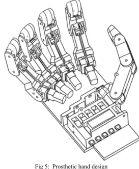
The developed design is shown in Fig 5. The design is dimensionally consistent with that of an average male human hand [2] and possesses the same degrees of freedom. The anthropomorphic aspect of the hand is intended to enhance the amputee’s acceptance and usability. The DIP and PIP joints of the finger and the IP and MCP joints of the thumb are coupled. This is achieved by connecting a single actuator to both the PIP joint (bevel gears) and DIP joint (pulley connection on metacarpal phalange). This coupling technique is common among many prosthetic/robotic hands as noted in the section above.
Fig 5: Prosthetic hand design
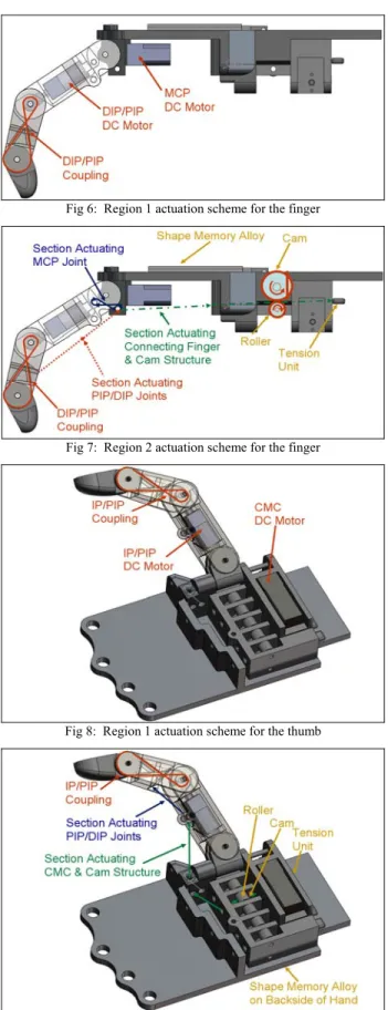
The developed parallel actuation structures discussed in the previous section are shown in Fig 6 and Fig 7 for the finger and Fig 8 and Fig 9 for the thumb. The movements associated with region 1 in Fig 4 are achieved by two DC motors. The DC motors actuating the coupled DIP/PIP joints of the finger and IP/MCP joints of the thumb are embedded in the proximal phalange of the finger and the metacarpal phalange of the thumb. The DC motor in the metacarpal phalange of the finger actuates the horizontal degree of freedom of the MCP joint. The DC motor at the base of the thumb actuates the CMC joint to obtain an approximation of the abduction/adduction motion. The second degree of freedom of the finger’s MCP joint (abduction/adduction) is only subject to compliance without actuation. The second degree of freedom in the thumb’s CMC joint (flexion/extension) is actuated by the region 2 actuation structure.
Fig 6: Region 1 actuation scheme for the finger
Fig 7: Region 2 actuation scheme for the finger
Fig 8: Region 1 actuation scheme for the thumb
Fig 9: Region 2 actuation scheme for the thumb
The actuation structure corresponding to region 2 in Fig 4 for the finger includes a light cable that passes over two restraining shafts in the MCP joint of the finger, coils in the proximal phalange, and embeds in the middle phalange. The
string is kept in light tension by a tension unit at the back of the hand while the region 1 actuation structure is active. When region 2 actuation is required the shape memory alloy actuates a spring loaded cam which in turn pinches the string between itself and a roller beneath it. As the shape memory alloy continues to actuate, the cam introduces the additional force required for region 2 tasks. At task completion the electric signal causing the shape memory alloy to heat up is stopped and the DC motors and cam spring extend the shape memory alloy back to its original state. The spring loaded cam mechanism is more definitively shown in Fig 10 and Fig 11.
Fig 10: Region 2 spring loaded cam mechanism prior to SMA actuation (thinner line representing cable corresponds to lower tension applied by
tensioner)
Fig 11: Region 2 spring loaded cam mechanism during SMA actuation (thicker line representing cable corresponds to additional tension applied by
SMA via cam mechanism)
The thumb’s region 2 actuation structure is similar to that of the finger’s region 2 actuation structure. However, unlike the finger, this structure actuates the degree of freedom at the CMC joint that is not actuated by the DC motor. This is based on the observation that this degree of freedom is more apposing of the fingers during tasks that would require additional force (power grasp, high force pinch grasp, lateral grasp, etc. [8]).
The design shown in this section has been manufactured using a rapid prototyping machine. The prototype can be seen in the Results and Discussion section.
IV. CONTROLLER DETAILS
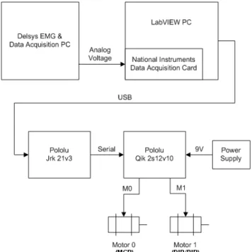
The control of the DC motors in this research was accomplished through the use of pulse width modulation (PWM) and direction control. PWM allowed the applied voltage to be varied continuously which controlled the speed and torque of the motor. Direction control was used to determine the spin direction of the motor.
PWM and direction control functionality was provided by a Pololu Qik 2s12v10. The Qik motor controller provides two channels of speed and direction control for brushed DC motors and is controlled by a serial interface. In this research, the motor controller was connected to a PC running LabVIEW to provide the serial commands. The connection from the PC to the Qik was made through an intermediate device, the Pololu Jrk 21v3, to provide the conversion from USB to the required serial connection. The Jrk also provides motor control functionality, but it was not implemented in this research.
Additionally, EMG signal capturing capability was added to control the DC motors. The raw signals from the EMG sensor are shown in Fig 12 and Fig 13.
Fig 12: Raw EMG signal with finger in relaxed state
Fig 13: Raw EMG signal with finger in flexed state
The raw signals were processed by taking the maximum absolute value over a 100 sample interval and generating a new data set. In order to get the full flex and extend ability of the finger from this new data set two threshold levels where introduced. Above one threshold the motor would spin in one direction (flex) and below another the motor would spin in the opposite direction (extend). The deadzone was implimented as a buffer area to transition between the flexation and extention zones.
The EMG signal was acquired from the first author’s digit III FDP muscle and supplied as an analog voltage from a separate PC incorporating a Delsys Bagnoli EMG system. The analog voltage was sampled through a National Instruments data acquisition card installed in the motor control PC. The analog signal was then filtered and scaled using LabVIEW to a value representing the amplitude of the EMG signal, which was then used to control the direction of the motors. A sample of the filtered and scaled signal with thresholds is shown in Fig 14.
Fig 14: EMG signal as finger was flexed and relaxed
The entire controller setup can be seen in the schematic shown below in Fig 15.
Fig 15: Motor controller setup
V. EXPERIMENTAL SETUP
The experiment associated with this research was performed to validate the designed actuation structure’s ability to span a two-region strength space similar to the one identified above for the human hand. The actuators used in the prototype were Pololu 298:1 Micro Metal Gearmotor HP DC motors [21] and the Electric Piston SMA actuator from Raychem [22]. These actuators are relatively inexpensive
and the implementation of more expensive actuators could further enhance the values reported below.
The experiment consisted of having the finger and the thumb grip a FSR sensor fastened to a dense foam ball in the large grip and then the close grip configurations as shown in Fig 16 through Fig 19. The large grip setup simulated the finger/thumb performing a more robust grasp on a larger object and the small grip setup simulated the actuation structure of the finger/thumb grasping smaller objects or performing the more dexterous pinch or lateral grasp. The values obtained experimentally are compared to the expected calculated values using a simple friction inclusive static calculation of the reaction force required at the FSR sensor to resist the stall torque of the DC motors and the measured tension provided by the SMA.
Fig 16: Finger in large grip configuration.
Fig 17: Finger in close grip configuration.
Fig 18: Thumb in close grip configuration.
Fig 19: Thumb in large grip configuration.
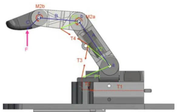
The experimental values were compared to the expected ones using friction inclusive static calculations based on the free body and geometric diagrams shown in Fig 20 and Fig 21. The “T” vectors in the free body diagrams represent the tension in the cable. The tension values are calculated using (1) where the Viand Vj are the geometric vectors of the cable on either side of a pivot point, ti and tj are the tension values in these vectors, and μ is the friction coefficient of the pivot point. Because tj is the only unknown in this equation it is separated and solved for in order to determine the next tension vector in the system.
(
tiVi −tjVj+tiViμ
)
= tjV (1)Fig 20: Primary variables used in friction inclusive static calculations of finger in both close and large grip configurations.
Fig 21: Primary variables used in friction inclusive static calculations of thumb in both close and large grip configurations.
With the tension vectors determined, the simple static equations (1) and (2) for the finger and thumb are used to solve for the forces/torques of each joint from the distal phalange to the knuckle in terms of the variable F value then using the equations to solve for F. The stall torque applied by the DC motors (90 oz-in) replaced the M1 and M2a/M2b variables. As described in the design section M2a and M2b are coupled and their relationship is shown in (3). The gravitational forces generated by each phalange was applied at the center of the link in the downward direction using the mass values for the finger of (Mprox=21.6g, Mmid=9.45g, Mdist=6.7g) and for the thumb of (Mmet=33.3g, Mprox=10.5g, Mdist=8.5g).
∑
M =0 (2)∑
F =0 (3) in oz b M a M + 2 =90 − 14 8 2 (4)VI. RESULTS AND DISCUSSION
Each of the four configuration setups were performed three times with each actuator type individually and then with them combined. The results are shown in Table 1 where the columns correspond to the resulting forces from the SMA, DC motors, the results of the SMA and DC motors column summed together, the experienced force when the two actuator types are physically applied at the same time, and the value calculated using basic statics. The table shows that when applied individually, the resulting forces from the SMA are for the most part larger than the applied DC motor forces for all four configurations. The average combined forces for the finger are generally greater than the experienced but the values for the thumb are approximately the same.
Table 1: Finger & Thumb Testing Results
Finger M1 & M2 & SMA (Newtons)
Finger CG SMA DC Motors Combined
(Sum) Combined (Experimental) Combined§ (Calculated) Combined£ (Calculated) Average 7.75 9.78 17.52 15.23 16.55 16.85 Std Dev 0.21 0.22 0.15 0.20 0.08 0.08
Finger LG SMA DC Motors Combined
(Sum) Combined (Experimental) Combined§ (Calculated) Combined£ (Calculated) Average 8.17 8.67 16.84 15.08 15.23 15.46 Std Dev 1.26 1.14 1.27 0.80 0.30 0.30
Thumb M1 & SMA (Newtons)
Thumb CG SMA DC Motor Combined (Sum) (Experimental)Combined Combined
§ (Calculated) Combined£ (Calculated) Average 4.70 1.24 5.94 5.60 5.14* 5.61* Std Dev 0.90 0.35 0.86 1.14 0.05 0.06
Thumb LG SMA DC Motor Combined
(Sum) Combined (Experimental) Combined§ (Calculated) Combined£ (Calculated) Average 4.56 3.45 8.01 8.18 7.70* 8.27* Std Dev 1.85 0.45 2.45 0.39 0.49 0.58
* Values combined from calculated SMA values and measured DC Motor values
§ Values where calculated using friction coefficients of μ(nylon)=0.102 and μ(steel)=0.09
£ Values where calculated using friction coefficients of μ(nylon)=0.52 and μ(steel)=0.09
The finger behavior is expected because the SMA was only partly isolated from the motors as the motors were still employed during the SMA test in order to maintain the structure of the finger against the ball prior to testing. This resulted in the SMA having to press against the ball and overcome the minor resistance presented by the motors. The thumb behavior was expected as well due to the slightly compliant units isolating the motor during the motor test absorbing some of the applied motor force. The calculated forces where also expectedly higher than the measured data as friction from the system was not incorporated in their development.
It is to be noted that the combined (calculated) values for the thumb are only calculated for the SMA input and the DC Motor experimental value has been added to the calculated value. This was done because a part of the component in the prototype thumb broke causing the gearing to not mesh appropriately, giving significantly smaller force values (approx. 3N) than those calculated (approx. 14N).
The controller was only applied to the DC motors of finger and thumb in their close grip configurations. The objective of these tests where to merely validate that the controller platform had the power and functional capacity to produce similar results to that of the power supply inputs using an EMG signal input.
The EMG voltage and current outputs for both the finger and thumb were consistent with that of the direct power supply inputs. The EMG thumb test resulted in a DC motor force of 0.95N which agreed with the 1.24N + 0.35N generated by the direct power supply tests. It was also visually verified that the finger squeezed the ball to a similar degree with the EMG controller as the direct power supply test system. However, a later identified disconnect in the FSR sensor did not allow the generation of reliable force data for the finger. Successive experiments for the finger resulted in a break in the rapid prototyped proximal phalange. This experiment is being repeated immediately with a soon to be re-built proximal phalange
VII. CONCLUSIONS AND FUTURE WORK
This paper presents a novel design and actuation system for a prosthetic hand. The actuation structure was shown to effectively span a two-region strength space to execute grip configurations similar to those found in the three primary grips of the human hand (power, pinch, and lateral). The design also showed the ability of an underactuated and nearly fully actuated kinematic structure to exist in a single actuation system using remarkably different types of actuators, without compromising the required size and weight of the prosthetic hand.
According to these results, the parallel actuation structure is a good starting point for the design. The results also validated that the design could be effectively driven by an EMG signal. Complete testing of the parallel actuation system’s performance will require the expansion of the EMG inputs to perform different grasps and manipulations.
Future work includes further testing, development of the controller, fabrication of a prototype that is more robust yet
of the same form as the rapid prototype components tested here, and the use of the dynamical model of the hand for manipulation tasks, in order to improve the design. More precisely selected actuators will be used in the final design. The stronger actuators will add the appropriate scale to the developed strength space so as to mimic the force generation capabilities of the system as well as the strength space form.
ACKNOWLEDGMENT
This research was performed under an award/contract from Telemedicine Advanced Technology Research Center (TATRC), of the U.S. Army Medical Research and Material Command (USAMRMC) of the U.S. Department of Defense.
REFERENCES
[1] Bicchi, A., 2000, “Hands for dexterous manipulation and robust grasping: a difficult road toward simplicity”, IEEE Transactions on Robotics and Automation, 16(6):652-662.
[2] Foegelle, M., Li, K., Pavacic, A., Moller, P., “Test & Measurement: Developing a Standard Hand Phantom for Wireless Testing,” [Online]. Available:
http://www.wirelessdesignmag.com/ShowPR.aspx?PUBCODE=055& ACCT=0029956&ISSUE=0811&RELTYPE=tm&PRODCODE=W02 60&PRODLETT=A&CommonCount=0,
[3] Norkin, C., Levangie, P., 1992, Joint Structure & Function: A Comprehensive Analysis: Second Edition, F. A. Davis Publications, 262-299.
[4] Nelson, D. L. “Tendon Laceration Page,” [Online]. Available: http://www.davidlnelson.md/Tendon_laceration.htm,
[5] Valero-Cuevas, F. J., Towles, J. D., Hentz, V. R., “Quantification of fingertip force reduction in the forefinger following simulated paralysis of extensor and intrinsic muscles,” Journal of Biomechanics 33 (2000) 1601-1609.
[6] Kevin G. Keenan, K. G., Veronica J. Santos, V. J., Venkadesan, M. and Valero-Cuevas, F.J., Maximal Voluntary Fingertip Force Production Is Not Limited by Movement Speed in Combined Motion and Force Tasks, The Journal of Neuroscience, July 8, 2009 • 29(27):8784–8789.
[7] Kutch, J. J., Valero-Cuevas, F. J., “All muscles are redundant but some are less redundant than others,” poster presentation for USC Viterbi School of Engineering Brain-Body Dynamics Lab. [8] Perez-Gracias, M. A., http://progeny.isu.edu/~alba/, Idaho State
University.
[9] Cutkosky, M.R., 1989, “On grasp choice, grasp models, and the design of hands for manufacturing tasks”, IEEE Transactions on Robotics and Automation, 5(3):269-279.
[10] Butterfass, J.; Fischer, M.; Grebenstein, M.; Haidacher, S. and Hirzinger, G.., 2004, “Design and Experience with DLR Hand II”, Proceedings of the World Automation Congress 2004, Seville, Spain, 2004.
[11] Touch Bionics Inc [Online]. Available: www.touchbionics.com [12] Shadow Robot Company [Online].
www.shadowrobot.com/hand/papers.shtml
[13] Fite, K., Withrow, T., Shen, Z., Wait, K., Mitchell, J., Goldfarb, M., 2008, “A Gas-Actuated Anthropomorphic Prosthesis for Transhumeral Amputees,” IEEE Transactions on Robotics, 24(1):159:169.
[14] Pylatiuk, C., Schulz, S., Kargov, A., Bretthauer, G., 2004, “Two Multiarticulated Hydraulic Hand Prostheses,” Artifical Organs, 28(11),980:986.
[15] I. Yamono, T. Maeno, 2005, “Five-fingered Robot Hand using Ultrasonic Motors and Elastic Elements,” Proceedings of the 2005 IEEE International Conference on Robotics and Automation, Barcelona, Spain, Aprill 2006.
[16] Andrianesis, K., Tzes, A., “Design of an Anthropomorphic Prosthetic Hand Driven by Shape Memory Alloy Actuators,” Proceedings of the 2nd Biennial IEEE/RAS-EMBS International Conference on
Biomedical Robotics and Biomechatronics, Scottsdale, AZ, USA, October 19-22, 08.
[17] Carrozza, M., Cappielo, G., Micera, S., Edin, B., Beccai, L., Cipriani, C., 2006, “Design of a cybernetic hand for perception and action,” Biol Cybern (2006) 95:629-644.
[18] Dollar, A.M., and Howe, R.D., 2006, “Joint coupling design of underactuated grippers”, Proc. of the ASME 2006 International Design Engineering Technical Conferences and Computers and Information in Engineering Conference, September 10-13, 2006, Philadelphia, PA, USA.
[19] Dollar Lotti, F., Tiezzi, P., Vassura, G., 2005, “Development of UB Hand 3: Early Results,” Proceedings of the 2005 IEEE International Conference on Robotics and Automation, Barcelona, Spain, April 2005.
[20] Hollerbach, J., “ME 6220: Introduction to Robotics”, Chapters 9 & 10 of Course Material, 2007.
[21] Pololu Robotics & Electronics, “298:1 Micro Metal Gearmotor HP,” [Online] Available: http://www.pololu.com/catalog/product/994 [22] Electric Piston Instruction Manual, [Online]. Available:
www.robotstore.com/download/EPiston_Instr_V12.pdf [23] Carrozza, M., Cappiello, G., Stellin, G., Zaccone, F., Vecchi,
F.,Micera, S., Dario, P., “A Cosmetic Prosthetic Hand with Tendon Driven Under- Actuated Mechanism and Compliant Joints: Ongoing Research and Preliminary Results,” Proc. of the 2005 IEEE International Conference on Robotics and Automation, April 2005, Barcelona, Spain.
[24] Vanderniepen, I., Van Ham, R., Van Damme, M., Lefeber, D., “Design of a powered elbow orthosis for orthopaedic rehabilitation using compliant actuation,” Proc. of the 2nd Biennial
IEEE/RAS-EMBS International Conference on Bimedical Robotics and Biomechatronics, October 19-22, 2008, Scottsdale, AZ, USA. [25] Zollo, L., Roccella, S., Guglielmelli, E., Carrozza, M., Dario,
“Biomechatronic Design and Control of an Anthropomorphic Artificial Hand for Prosthetic and Robotic Applications,”
IEEE/ASME Transactions on Mechatronics, Vol. 12, No. 4, August 20007.
[26] Engeberg, E. D., Meek, S., “Improved Grasp Force Sensitivity for Prosthetic Hands Through Force-Derivative Feedback,” IEEE Transactions on Biomedical Engineering, Vol. 55, No. 2, February 2008.
[27] Engeberg, E. D., Meek, S., “Model-Based Feedforward Derivative Compensation for Prosthetic Hands,” Proc. of the 2nd Biennial
IEEE/RAS-EMBS International Conference on Bimedical Robotics and Biomechatronics, October 19-22, 2008, Scottsdale, AZ, USA. [28] Engeberg, E. D., Meek, S. G., Minor, M. A., “Hybrid Force-Velocity
Sliding Mode Control of a Prosthetic Hand,” IEEE Transactions on Biomedical Engineering, Vol. 55, No. 5, February 2008.
[29] Cipriani, C., Zaccone, F., Micera, S., Carrozza, M., “On the Shared Control of an EMG-Controlled Prosthetic Hand: Analysis of User-Prosthesis Interaction,” IEEE Transactions on Robotics, Vol. 24, No. 1, February 2008.
[30] Blank, A., Okamura, A. M., Kuchenbecker, K. J., “Effects of Proprioceptive Motion Feedback on Sighted and Non-Sighted Control of a Virtual Hand Prosthesis,” Symposium on Haptic Interfaces for Virtual Environments and Teleoperator Systems, March 13-14, 2008, Reno, Nevada, USA.
[31] Robinson, D. W., Pratt, G. A., “Force Controllable Hydro-Elastic Actuator,” Proc. of the 2000 IEEE International Conference on Robotics and Automation, April 200, San Fransico, CA, USA. [32] Pylatiuk, C., Schulz, S., Kargov, A., Bretthauer, G., 2004, “Two
Multiarticulated Hydraulic Hand Prostheses,” Artifical Organs, 28(11),980:986.
[33] Institute of Robotics and Mechatronics [Online]:
http://www.dlr.de/rm/en/desktopdefault.aspx/tabid-3975/6161_read-245/
[34] Winfrey, Rex C., 2008, “Prosthetic Hand Having a Conformable, Compliant Grip, and Opposable, Functional Thumb,” Patent 7,361,197, April 22, 2008.
![Fig 1: Joint/Bone composition of human hand [2]](https://thumb-us.123doks.com/thumbv2/123dok_us/841147.2606933/1.918.523.771.764.1040/fig-joint-bone-composition-human-hand.webp)