This paper is included in the Proceedings of the
13th USENIX Symposium on Networked Systems
Design and Implementation (NSDI ’16).
March 16–18, 2016 • Santa Clara, CA, USA
ISBN 978-1-931971-29-4
Open access to the Proceedings of the
13th USENIX Symposium on
Networked Systems Design and
Implementation (NSDI ’16)
is sponsored by USENIX.
Diamond: Nesting the Data Center Network
with Wireless Rings in 3D Space
Yong Cui and Shihan Xiao,
Tsinghua University;
Xin Wang,
Stony Brook University;
Zhenjie Yang and Chao Zhu,
Tsinghua University;
Xiangyang Li,
Tsinghua University and
University of Science and Technology of China;
Liu Yang,
Beijing University of Posts and
Telecommunications;
Ning Ge,
Tsinghua University
Diamond: Nesting the Data Center Network with
Wireless Rings in 3D Space
Yong Cui
1, Shihan Xiao
1, Xin Wang
2, Zhenjie Yang
1, Chao Zhu
1, Xiangyang Li
1,3, Liu Yang
4,
and Ning Ge
11
Tsinghua University
2
Stony Brook University
3
University of Science and Technology of China
4
Beijing University of Posts and Telecommunications
Abstract
The introduction of wireless transmissions into the da-ta center has been shown to be promising in improving the performance of data center networks (DCN) cost ef-fectively. For high transmission flexibility and perfor-mance, a fundamental challenge is to increase the wire-less availability and enable fully hybrid and seamwire-less transmissions over both wired and wireless DCN com-ponents. Rather than limiting the number of wireless ra-dios by the size of top-of-rack (ToR) switches, we pro-pose a novel DCN architecture, Diamond, which nests the wired DCN with radios equipped on all servers. To harvest the gain allowed by the rich reconfigurable wire-less resources, we propose the low-cost deployment of scalable 3D Ring Reflection Spaces (RRSs) which are in-terconnected with streamlined wired herringbone to en-able large number of concurrent wireless transmissions through high-performance multi-reflection of radio sig-nals over metal. To increase the number of concurrent wireless transmissions within each RRS, we propose a precise reflection method to reduce the wireless interfer-ence. We build a 60GHz-based testbed to demonstrate the function and transmission ability of our proposed ar-chitecture. We further perform extensive simulations to show the significant performance gain of Diamond, in supporting up to five times higher server-to-server capac-ity, enabling network-wide load balancing, and ensuring high fault tolerance.
1 Introduction
The high-performance data center network (DCN) is an essential infrastructure for cloud computing. There is a quick growth of large-scale services (e.g., Google Search, Hadoop, MapReduce, etc.) in the cloud, and recent measurements show tremendous traffic variations over space and time in DCNs [5, 7, 8, 20]. Convention-al wired DCNs generConvention-ally adopt the fixed and symmetric network design. This may lead to prevalent hot spots
across different layers of the architecture which signifi-cantly reduces the performance of DCNs [7, 20, 37].
There are some recent interests on constructinghybrid
DCNs [18, 19, 33, 38, 39] with the introduction of new network components such as optical circuit switches or wireless radios into the DCNs to provide configurable links [9,13,25,28]. Although these hybrid infrastructures show the potential in achieving higher DCN capacity and lower transmission delay, their wired structures are kept unchanged even though they are not primitively designed to work with new network techniques, which limits the performance of hybrid DCN. Specifically, the new net-work components are added directly into conventional DCNs or are applied to replace part of existing network switches [18, 33, 38, 39]. Considering only thelocal per-formance improvement, it is hard for existing schemes to achieve the global optimal performance in the presence of network-wide traffic changes. The key challenge of a
fully hybridnetwork design is to form a novel hybrid net-work architecture that can take full advantage of differen-t nedifferen-twork differen-techniques and enable coherendifferen-t and seamless transmissions for much higher DCN performance.
The low cost of today’s commodity 60GHz radios makes their wide deployment a better option in a ful-ly hybrid network design [39]. Providing high wireless availability in the data center is the key to achieving high performance gain in a hybrid architecture. In existing proposals for hybrid DCNs, wireless radios are generally deployed on a flat 2D plane at the top of racks, which is susceptible to signal blocking [38]. Although a flat reflector on the room ceiling was proposed to alleviate the problem [19,38], the ceiling height is quite restricted (3 meters [38]) and the method requires clearance above racks, which is usually infeasible in conventional data centers. The small rack size also restricts the number of radios that can be placed on each rack (at most eight ra-dios per rack [38, 39]). If rara-dios are densely deployed on top of racks, the strong inter-ratio interference would restrict the number of concurrent wireless links thus
con-straining the system performance [39]. The need of de-ploying more radios and links in the hybrid network for higher wireless availability calls for a completely new DCN architecture design.
In this work, we propose a novelfully-hybridnetwork architecture, named Diamond, which ensures high wire-less availability for efficient and high-performance DCN communications. Rather than restricting the radios to be on top of racks, we propose to deploy wireless ra-dios along with a large number of servers. To avoid the interference among dense radios at the 2D plane, we propose to construct multipleRingReflectionSpaces (RRSs) to make the radios sparsely distributed in the 3D space. Inside each RRS, we develop a novel multi-reflection method to address the blocking problem on building wireless links. With our design, there is no need of changing the room plan above racks. Diamond has three key design features:
Novel hybrid network topology (§2): Rather than adding wireless radios directly on top of racks, we pro-pose a fully hybrid network topology by constructing RRSs in Diamond to facilitate wireless transmissions and isolate the wireless interference. It also supports direc-t server-direc-to-server wireless links radirec-ther direc-than convendirec-tional rack-to-rack links. Then we apply a streamlined wired herringbone to interconnect the RRSs at low cost.
Precise multi-reflection of wireless links (§3): The susceptibility to blocking and the interference are two major issues that limit the wireless performance in DCN-s. To the best of our knowledge, this is the first work that develops the multi-reflection transmission method to ad-dress the challenge of signal blocking. We further design a novel precise reflection scheme to efficiently restrict the wireless interference in the presence of a large number of concurrent wireless links.
Wireless & wired hybrid routing (§4): We propose an opportunistic hybrid routing scheme to allow for low transmissions delay and graceful fault tolerance. We fur-ther show that the network diameter of Diamond can s-cale logarithmically with the server number to effectively bound the route length.
We implement a 60GHz-based testbed, and our exper-imental results confirm the high performance of multi-reflection, and demonstrate that proper reflection holes can efficiently reduce the interference in 3D space (§6). Driven by the testbed parameters, our simulations show that Diamond can support up to five times higher server-to-server capacity and ensure graceful fault tolerance (§7). Finally, we introduce the related work (§8) and draw the conclusions (§9).
2 Architecture
In this section, we first introduce the basic architecture and methodologies used in the Diamond system, and
then present its hybrid topology design.
2.1 Diamond system overview
At a high level, the Diamond system should meet the data center needs at different timescales. First, the configura-tion of wireless links should be updated periodically so that the network topology can better accommodate the current traffic of the data center. Second, given a con-figured network, we need to efficiently route the flows in real time.
Dynamic wireless configuration: Following the pri-or studies, the Diamond system exploits the controller of software-defined networking (SDN) for flexible and efficient configuration of the wireless links and routing paths [4,11,26,27]. More specifically, the Diamond con-troller periodically updates the configuration of the wire-less links based on the traffic conditions reported from SDN-controllable ToR switches. Servers are equipped with high-capacity wireless radios (60GHz radio [18] or FSO transceivers [19]). To dynamically configure the wireless links, they are allowed to communicate with each other either directly by steering and aligning the antennas (physically or electronically driven [18, 19]) or using a multi-reflection method we propose. The con-troller first builds wireless links to alleviate the heavy traffic from the hot spots, and then randomly forms addi-tional wireless links using the remaining available radios to achieve the benefits of random networking [31].
Hybrid routing: The controller only computes the routing paths of hot-spot server pairs during the wire-less configuration to alleviate the hot-spot traffic globally for the network-wide load balancing thus higher network throughput. For other light-loaded server pairs, the rout-ing decision is made distributedly by servers and switch-es so that their traffic can go through available wirelswitch-ess links opportunistically to cut short the routing paths in real time.
2.2 Key methodologies
There are two main challenges to implement a fully hy-brid network: (1) When a large number of wireless links are enabled, the interference will restrict the number of concurrent transmissions; and (2) When a large number of wireless radios are deployed, the high-frequency wire-less links are easily blocked by obstacles such as the sup-ply pipes of air conditioning or the steel structures above racks. In light of these problems, Diamond applies a 3D deployment of the wireless radios to facilitate high num-ber of concurrent wireless transmissions taking advan-tage of the following key techniques:
Space division multiplexing: To disperse the wireless radios, the radios in Diamond are installed with servers at different heights. Rather than deploying the wireless
radios densely on only one flat 2D plane, we place the wireless radios on several separated large annular sur-faces. Thus the deployment density of wireless radios is much lower than that of previous studies [38, 39]. The adjacent annular surfaces form a RRS where the signal can run from one radio to another. Due to the space di-vision, the same set of wireless channels can be multi-plexed across different RRSs, which helps isolate the in-terference in Diamond.
Multi-reflection transmission: Although more radios can be deployed in a 3D space, many radios cannot reach each other with existing direct point-to-point transmis-sion or the one-reflection transmistransmis-sion [18, 19, 38, 39] due to the obstacle blocking. Instead, in Diamond, we utilize multiple reflections to bounce the signal emitted from one server to another. This helps to greatly increase the number of available wireless links. Following the pri-or wpri-ork [38], our testbed experiment confirms that using the flat metal board as reflector can offer very good spec-ular reflection with little energy loss or changing path loss during each reflection. This avoids the overhead of buffering and switching packets in multiple hops over in-termediate switches.
Different types of directional antennas may have d-ifferent beam widths [18]. For a multi-reflection path, there is a tradeoff between the antenna beam width and the tolerance for the antenna alignment error. The nar-rower the beam width, the higher the antenna gains, but the less the alignment error tolerance. In the ex-treme case of using FSO with nearly zero beam width, previous study shows that using electrically-driven Gal-vo mirrors is possible to implement precise steering control [19]. For conventional 60GHz antennas, the electrically-driven antenna array is promising to satisfy this requirement [18, 39].
Precise reflection technology: Since the wireless an-tenna may have a wide beam width [18], multiple re-flections would introduce unexpected interference inside the 3D space due to the signal leakage of the beam (e.g., the undesired side lobes of the 60GHz wireless beam [18, 29]). In order to efficiently restrict and con-trol the interference caused by reflections, we develop a precise reflection method with the careful placement of absorbing materials on the reflection boards. Most areas of the board are covered by absorbing paper while small holes are left so that only the intended signal reflections are made by hitting the hole, which leads to very little signal leakage.
2.3 Topology design
The basicmotivationof the Diamond topology design is to enable more concurrent wireless transmissions. In our design, we separate the specific transmission functions of wireless and wired links in the network, so that both
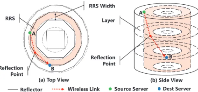
Reflector Wireless Link Source Server
(a) Top View (b) Side View
Dest Server A B A B RRS A Reflection Point Layer Reflection Point RRS Width
Figure 1: Brief view of the wireless ring in Diamond (N=4 rings and H=4 layers)
their distinct advantages on the transmission can be ful-ly explored. We construct a ring-shape basic structure that enables wireless-only transmissions inside the ring employing the multi-reflections (§2.2). Then we apply the stable wired links to address the transmissions across different ring structures.
From the top view in Fig. 1, Diamond’s topology is constructed by several concentric regular polygons with increasing radius. Polygons are numbered from inside to outside and named by rings, i.e., {Ri}, 1≤i≤N,
whereN is the total number of polygons. Theith ring
has 4iedges. The racks are placed at the vertex points of each ring, and there are totally 1≤i≤N(4i) =2(N2+N)
racks, while flat metal reflectors are put at the edge of each ring. Rather than mounting the reflectors [19,38] on the ceiling, reflectors in Diamond stand in perpendicular to the ground and have the same height as that of racks, which avoids the need of using clear ceiling space for wireless transmissions in data centers. In the following, we introduce the designs of major Diamond components.
Server and rack. Each rack holds multiple servers at different height. The servers inside different racks at the same height form alayer, and the layers are num-bered from the top to the bottom as{lj}, 1≤j≤H. The
height of each layer equals the height of a server at con-ventional racks, and the number of layersHequals to the number of servers in one rack. Therefore, a Diamond topology can accommodate totally 2(N2+N)H
server-s. Each server is equipped with 1 Ethernet port and 2 wireless ports with directional antennas. The network-ing principles in Diamond are: (1) the links between two servers are wireless; (2) the links between a server and its ToR switch or between two ToR switches are wired.
Wireless links: The 3D space between two neighbor-ing rneighbor-ings is called an RRS. For each server, one of its antennas points to RRS at its inner side and the other points to RRS at its outer side. By adjusting the antenna directions in the RRS, each server at ringRi can
flexi-bly communicate with other servers at different heights on ringsRi,Ri−1andRi+1through direct transmissions
or multiple reflections on different reflectors (Fig. 1 and Fig. 3).
Virtual Switch Row
ToR Switch
Reflector Column
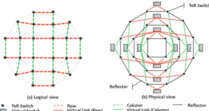
(a)Logical view (b) Physical view
ToR Switch
Virtual Link(Row) Virtual Link(Column) Reflector
Figure 2: Top view of the wired herringbone of Diamond (N=3 rings)
Wired links: With wireless links formed locally inside each RRS, the wired links are applied to intercon-nect different RRSs. Fig. 2 gives a top view of the wired connections in Diamond. Similar to conventional DCN-s, the servers on each rack are connected to the common ToR switch. Fig. 2(a) shows the logical view of thewired herringbone. We number the horizontal lines in Fig. 2(a) from the top to the bottom as rows {ri}, 1≤i≤2N,
and number the vertical lines from the left to the right as columns{ci}, 1≤i≤2N. Fig. 2(b) shows the
phys-ical connections of the wired herringbone. The princi-ple of Diamond to interconnect the RRSs is that the ToR switches on the same row (or column) are interconnected by avirtual switch, while the ToR switches on different rows and different columns are not directly connected.
To implement the function of virtual switch, we have the option of applying any existing structure, e.g., the tree-based structure (Fat-tree [3]) or cube-based structure (BCube [16]), to interconnect the ToR switches on each row and each column. These structures may make the wired design of Diamond complex and costly. In Di-amond, we prefer to apply the de-Bruijn graph [12] so that no additional switches are required. De-bruijn is at-tractive for providing constant link degree at each node and logarithmic network diameter. Then the path length is bounded and the routing structure is still simple (§4). Although using de-Bruijn structure often involves com-plex wiring [17], the wiring is kept simple in Diamond because only one row (or column) of ToR switches are connected as one de-Bruijn.
2.4 Rack and reflector arrangement
There are two requirements to arrange the racks in Dia-mond to facilitate its practical and scalable deployment: first, all the reflector boards should be flat and have the same length to facilitate their economical production; second, the RRS width should be kept stable, with the RRS width close to a fixed value when the number of rings increases. We call the physical distance between two neighboring ringsRi andRi+1as the RRS widthΔi
(Fig. 1). Too large a RRS width will make Diamond
oc-C
Reflection Path Wireless/Wired Hybrid Path Wired Link
Wireless Link Source Server Dest Server
Reflection Points
Figure 3: Routing in the 3D wireless ring cupy too much room area, while too small a RRS width will not leave enough space for wireless transmissions.
As mentioned earlier, all the polygons in Diamond are regular with the same edge length and are put concen-trically in a symmetric way as shown in Fig. 2. The re-flector height equals the height of racks, and the rere-flector length is denoted asL. Then our design ensures the RRS widthΔiatith ring to have the following property:
Property 1. lim
i→∞Δi=2L/π
Proof. Based on the topology of Diamond, the radius di of ring Ri is di = (cot4πi)L2. Then we have Δi =
di+1−di= (cot4(iπ+1)−cot4πi)L2= sin(π4i(i+11)) sin[(π4)2i(i+11)] L 2. Hence we havelim i→∞Δi=2L/π.
Based on the above proof, the RRS widthΔi
decreas-es as the ring numberibecomes larger. Property 1 en-sures that the RRS width does not fall to zero but reach-es a fixed limit value. For a setting L=2.5m, the RRS widthΔi can keep a value close to the fixed limit value
1.6m. We can see that the RRS width becomes stable and approaches the fixed limit value quickly when the ring number increases, which demonstrates the scalability of the Diamond design.
3 Wireless configuration
In this section, we first introduce our schemes of find-ing the reflection path when buildfind-ing a wireless link and eliminating the wireless interference during the reflec-tions, and then present our strategies in forming flexible wireless configurations for network-wide load balancing.
3.1 Reflection path
Since the physical topology of Diamond is fixed, the re-flection paths can be easily calculated between any two servers. The calculation of the reflection path table is done offline at the initial deployment of Diamond. If there are multiple paths available between two servers, we choose the one with the least number of reflection
4 5 6 7 8 9 0 20 40 60 80 Number of reachabl e racks Index of ring 0-reflection 1-reflection 2-reflection 3-reflection Upper bound
Figure 4: Number of reach-able racks per server at ferent rings and within dif-ferent reflection times
5 10 15 20 25 30 35 40 45 50 0 0.1 0.2 0.3 0.4 0.5 0.6 0.7 0.8 Index of ring Reuse ratio
Figure 5: Reuse ratio of re-flection points on a board at different rings
times (direct transmission is considered as zero times of reflection). Given a source server and a destination serv-er in Diamond, if a reflection path can be found in the table, the antenna angles can be adjusted by the servers according to the table values to build the wireless link.
Based on the Diamond topology, we simulate the re-flection paths between all the server pairs. Fig. 4 shows the average communication range of a wireless radio, i.e., the reachable rack number at both its current ringRi
and inner ringRi−1. We can see that no more than three
reflections can cover above 90% racks in the RRS when the ring number is less than 9. For a ring number larger than 4, a server can reach at least 10 racks through the di-rect transmission, 20 racks within a single reflection and 28 racks within two reflections.
3.2 Reduction of wireless interference
We design a precise reflection method to alleviate the wireless interference during reflections. Specifically, we carefully place the absorbing materials on the reflection board and leave smallholesfor only the intended reflec-tion points. In the following, we analyze the density and distribution of reflection points (i.e., the reflection holes) on the reflector boards.
To simplify the analysis, we first present a special cir-cle casewhere the flat reflectors are replaced by curved reflectors so that all the polygons are transformed to their circumcircles. We consider the communication of servers inside thekth RRS, i.e., the communication be-tween a server on ringkand another on ringk+1 and the
communication between two servers on ringk+1. The
reflection times are limited within three. The commu-nication of servers in different rings is achieved by zero and double reflections. The double reflection forms the reflection points on the outer side of ringkand the inner side of ringk+1.
Considering the distribution of reflection points on ringk, we have the following property:
Property 2. At each layer of Diamond, for an arbitrary reflector on ring k, there are at most six reflection points on the reflector board.
Proof. Based on the coordinates of a server n on ring k+1and a server m on ring k, we obtain the central
an-gle for each reflection point, denoted as 2
3·π4((2kn+−11))+13·
π(2m−1)
4k , m,n∈Z+. We shift the value of m and n to find
the minimum change of the central angle of the reflection point. The minimum change 12πk is the minimum inter-val of two reflection points. As the central angle for the reflector on ring k is 2πk, there are at most six reflection points at each layer of the reflector board. This com-pletes the proof.
We obtain the expressions of the central angle for each reflection point in ringk+1 following the same
proce-dure of ringk. We examine the distribution of reflection points on each reflector in ringk+1 based on simulation
results, and found that at each layer from the ring 5 to the ring 50, there are average ten reflection points on the board of the ringk+1. One hole may be reused by a large
number of reflection points for different reflection paths, i.e., the distance between two reflection points is small enough to overlap with each other. With the reuse ratio equal to the ratio of reused points to the total number of reflection points, Fig. 5 shows that the reuse ratio is high and increases when the ring number becomes larger.
3.3 Configuration for hot-spot traffic
Since the above techniques enable a large number of server-to-server wireless links, Diamond can implemen-t a neimplemen-twork-wide reconfigurable implemen-topology for balancing the identified hot-spot traffic, which contributes to high throughput and effective routing.
Configuration problem: The wireless configuration is determined by the network controller in DCNs. The controller input is a traffic demand matrix where an en-try describes the traffic demand between a pair of servers. Given a hybrid topologyG, we can construct its interfer-ence graph GI1to describe the conflict relations among
all the wireless links based on offline measurements [18]. The objective of our wireless configuration is to select the optimalindependent set(IS)2to minimize the
max-imum link utilization of the entire network during each scheduling period. We thus have an integer linear pro-gramming (ILP) problem HLBP (Hybrid Load Balance Problem). Our HLBP problem mainly differs from pre-vious study Firefly [19] on the additional wireless inter-ference constraint on IS selections. Finding all the ISs is NP-complete in general [14]. We find that even the state-of-art ILP solver LINGO or ILP toolbox in MAT-LAB may take above tens of minutes to solve the HLBP.
1Theindependent graph GIofGis defined as a graph where each
link inGcorresponds to a vertex inGI, and if two links have conflict inG, then there is a link between them inGI.
2Anindependent set(IS) in an interference graphGIis defined as a
DH DW BC 3DB FT 0 0.2 0.4 0.6 0.8 1
Path Length Ratio
6 5 4 3 2 1 Hops
Figure 6: Path length ratio of different topologies There are some existing studies [21–23, 34–36] on find-ing an approximate IS solution in some special interfer-ence graphs. In the following, in order to make Diamond support various types of antennas, we turn to the develop-ment of a fast heuristic solution for a general interference graph.
Greedy scheduling: We design a greedy algorithm HDF (Highest Demand First) to provide a faster and sim-pler solution for HLBP. The algorithm assigns a weight value to wireless links related to the flows, and then s-elects a set of non-conflict wireless links that maximize the sum of weights. We define the weight of a wireless link as the ratio between the flow demand and the link length. For a link with reflections, the link length is the total geometric length of the reflection path. The intu-ition is that a link can provide larger benefit when serving higher flow demand over a shorter link length, as a short-er wireless link allows for smallshort-er intshort-erfshort-erence range and higher SNR thus higher link capacity. We greedily select the links with the largest weight to build first and remove the links that conflict with the selected links. Next, the traffic demands are split into their shortest paths. Denote the minimum remaining capacity of links along a path as the path capacity. The server pair with the highest demand first splits the traffic to transmit over the set of shortest paths in proportional to the path capacity. Then the remaining link capacities are updated and the proce-dure repeats until no server pair is left. The gap between HDF and the optimal solution is evaluated in§7.
3.4 Random networking for high capacity
and low delay
Since the wireless resources are rich in Diamond, after offloading the hot-spot traffic by HDF, some wireless ra-dios may be left unused, particularly when the number of hot spots in the network is not big in a scheduling peri-od. Random networking is shown to have the features of small average path length, high path diversity and high server-to-server network capacity [31, 32]. Thus we ex-pect that the random formulation of wireless links helps to shorten the path length in Diamond.
To verify this effect, we compare the percentage of the path length for all the server pairs under different DCN topologies with 512 servers in Fig. 6. DH is for Diamond where wireless links are built randomly; DW is for Dia-mond with the wired connections only; BC is the BCube
topology [16]; FT is the Fat-tree topology [3]; 3DB is a Fat-tree topology augmented by 3D-beamforming ra-dios at ToR switches [38]. We can see that the number of long paths in DW is larger than that in BCube. Howev-er, when introducing random wireless links, the ratio of short paths in DH is higher than all the other topologies. The short path length generally implies small hop delay and high end-to-end throughput due to fewer congestion points at intermediate routing hops [31, 32].
To benefit from the random networking in Diamond, we extend the IS selected by the HDF algorithm to a
maximal IS, named the MIS, by randomly adding addi-tional wireless links into the IS without creating conflic-t unconflic-til no such kind of wireless link is available. The random formulation of wireless links in Diamond avoids the problem of complex wiring and costly management appearing in the previous work on using random wired links in DCNs [32].
4 Routing Design
Diamond is built upon a topology-adaptive network, while existing routing protocols often impose a relative-ly long convergence time when the topology changes [6]. For more efficient routing, we propose to use a set of s-trategies in Diamond.
4.1 Overall scheme
The setup of wireless links is performed by the Dia-mond controller periodically. We denote the time in-terval for the controller to execute the wireless recon-figuration as oneperiod. At the beginning of each pe-riod, a set of operations will be performed as follows: (1) The controller computes the wireless configuration and the routing paths for hot-spot server pairs using the methods described in§3, and sends out the instruction-s to both instruction-serverinstruction-s and their ainstruction-sinstruction-sociated ToR instruction-switcheinstruction-s. (2) The servers receiving the configuration instructions will adjust their antenna directions accordingly.
To summarize, there are three choices for a server or ToR switch to route its traffic. First, a server or ToR switch tries to match the routing rules designated by the controller. If matched, it delivers the packet according-ly. This first choice helps to balance the hot-spot traffic following the controller’s decisions. Otherwise, it oppor-tunistically utilizes its available wireless radios (if it is a server) or the available radios on its rack (if it is a ToR switch) to create a short-cut hop to the destination. This second choice contributes to shorter routing path through opportunistic hybrid routing. If no wireless radios are proper to use, it delivers the packet to the next-hop node following a default wired routing path. This last choice efficiently bounds the worst-case performance by routing through the wired herringbone.
4.2 Default wired routing
For the Diamond topology introduced in§2.3, a 3-tuple
(x,y,z)labels a server at thexth row,yth column andzth
layer. For simplicity, we use a 3-tuple(x,y,0)to label a
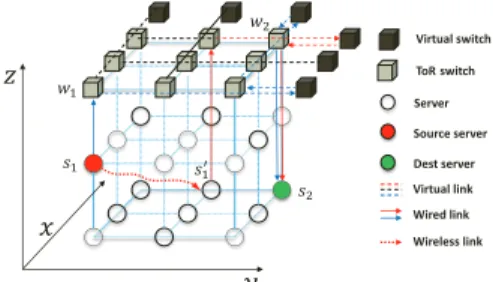
ToR switch on thexth row andyth column. Fig. 7 shows a simple example to route from an arbitrary source serv-ers1= (x1,y1,z1)to a destination servers2= (x2,y2,z2).
Let w1= (x1,y1,0) and w2= (x2,y2,0) denote their
corresponding ToR switches respectively. The shortest wired routing path can be established as follows. First, the packet routes froms1tow1and then we change one
of the two coordinates of source ToR switchw1at a time
to match that of switch w2: (x1,y1,0)→(x2,y1,0)→
(x2,y2,0). Finally, the packet routes fromw2tos2. Note
that each coordinate change corresponds to hops through a virtual switch.
Suppose we apply de-Bruijn structure to implemen-t implemen-the virimplemen-tual swiimplemen-tch, and implemen-the Diamond implemen-topology has implemen-toimplemen-tal- total-lyH=2players andNrings. Then we need 4pports per
ToR switch, where 2pports connect to the servers on the rack and 2pports are used for constructing the de-Bruijn on its row and column. Since the diameter of a de-Brujin graph is logpN, the path length through a virtual switch (i.e., the path length between two ToR switches on one row or column) can be bounded by logpN. Based on the
above routing procedure, we have the property:
Property 3. The network diameter, which is the longest shortest path among all the server pairs, of Diamond is bounded by2logpN+2.
Since the Diamond withHlayers andNrings can sup-port totallyn=2(N2+N)Hservers, we have the
diame-ter of Diamond asO(logpn). Compared to conventional
approaches (e.g., the Fat-tree [3] or VL2 [15] topology) which has a constant diameter but the number of switch ports increase with the number of servers, Diamond has much better scalability. As the server number increases, its network diameter extends logarithmically while the port number can be kept as a constant. This is similar to the recursion-based DCN topology such as BCube [16] and DCell [17]), which also has a logarithmic diameter when keeping a constant number of switch ports.
4.3 Opportunistic hybrid routing
The wired herringbone of Diamond provides the basic assurance of the connectivity and route length bound. Now we integrate the wireless transmissions into the default wired paths opportunistically. Suppose a serv-er s1= (x1,y1,z1) receives a packet for a server s2=
(x2,y2,z2), and the ToR switches ofs1ands2arew1=
(x1,y1,0) and w2 = (x2,y2,0). The server s1 is
e-quipped with two radios, which are pointed to servers
s�
1= (x3,y3,z3)ands��1= (x4,y4,z4), respectively. Define
Virtual switch ToR switch Server Source server Dest server Virtual link Wired link Wireless link ݔ ݕ ݖ ݏଵ ݓଵ ݏଶ ݓଶ ݏଵᇱ
Figure 7: Opportunistic hybrid routing in Diamond ahamming distanceD(s1,s2)as the number of the
un-matched coordinates between the tupless1ands2. Then
the value range ofD(s1,s2)is{0,1,2,3}.
To perform the opportunistic hybrid routing (OHR), each server in Diamond simply follows two steps for the packet forwarding: (1) Calld1=D(s1,s2). If all three
are matched (i.e.,d1=0), then it is the destination
serv-er. (2) Calld�
1=D(s�1,s2)andd��1=D(s��1,s2). Ifd1� <d1
ord��
1<d1, forward the packet to the servers�1ors��1
ac-cordingly through a wireless radio. Otherwise, forward the packet to the switchw1by default.
Similar to the servers, each ToR switch in Diamond forwards the packet as follows: (1) Calld1=D(w1,s2).
If the first two are matched (i.e.,d1=1), it forwards the
packet tos2directly; Otherwise, it randomly chooses one
coordinate among the unmatched ones. Assume that ToR switch picksx1wherex1�=x2, then the default next hop
iswf = (x2,y1,0). (2) For each serversi in the rack,
suppose its wireless radios point to two servers s�
i and
s��
i. Calldi�=D(s�i,s2)anddi��=D(s��i,s2). Ifd1� <d1or
d��
1 <d1, forward the packet to the seversi in the rack;
Otherwise, forward the packet to the ToR switchwf by
default.
4.4 Fault-tolerance
The redundancy of available paths between any pair of servers make Diamond attractive for fault-tolerance. There are two types of failures to handle in Diamond: node failure and link failure. Three classes of node fail-ure should be considered: (a) switch failfail-ure, (b) server failure and (c) wireless radio failure. A link failure will be resulted from a node failure, or the change of the en-vironment such as the blocking of wireless communica-tions due to the human movement in the RRSs. Clearly, due to the nested structure of Diamond, any single node or link failure does not lead to the network disconnec-tion. We describe link failures here because other node failures trigger the same responses.
In Diamond, each server has three different output links to forward the packets: (a) forward to the ToR switch it connects to; (b) forward to one of its two wire-less radios. When a server finds one of its output links fails, it removes that wired/wireless connection from its
connection list, and chooses one of the remaining avail-able output links as its next hop based on the routing rules described in Section 4.3. Benefited from the distributed routing property of OHR, the routing paths can be recov-ered quickly in Diamond to ensure high fault tolerance.
5 Discussion on deployment issues
Circle vs. Polygon reflector. We have so far suggested using the flat mental board as the reflector to facilitate its economic production and easy deployment. If the cost is not a concern, however, a curved mental reflector would allow the wireless communication range of each server to be larger than that of the flat reflector for the same con-straint on reflection times. Considering that the curved reflectors are used to construct the circumcircle of each ring, with the ring number varying from 5 to 100 and the reflection times set to be within three, we find that the average wireless communication range per server in the polygon case is above 80% that of the circle case. When the number of rings is smaller than 5, both cases ensure the communications of all the servers of the entire ring. The results indicate that using flat reflector is a better choice for the deployment in a large-size data center.
Design of virtual switch. Diamond introduces a virtu-al switch to interconnect the ToR switches on a line (row or column) and the virtual switch can be implemented by any existing interconnection structures, e.g., the tree-based structure [3, 15] or cube-tree-based structure [2, 16], with different trade-offs between the cost and perfor-mance. However, the number of ports required by a vir-tual switch on different rows and columns may not be the same in Diamond. Consider a Diamond topology with 2n
rows and 2ncolumns, the port numbers of virtual switch from rowr1tornare{2,4,6, ...,n−2,n}. The uneven
port numbers make it difficult to deploy conventional in-terconnection structures as some structures do not scale continuously [3,16,17]. To address this issue, we suggest using one virtual switch to interconnect two rows (or two columns) together to make a balance of the port number. Then each virtual switch requiresn+2 ports by
combin-ing every two rows as(r1,rn),(r2,rn−1),(r3,rn−2)and so
on. We can obtain the same result as that of 2n+1 rows
and columns by excluding the median row and column.
Rack density and wireless link number. To pro-vide an idea of the deployment density of Diamond, we give an example. A room of data center with the size 100×100m2 can hold 2k racks if using Diamond, and
Table 1: Total cost of different DCN architectures
Topology Cost (k$) Power # NIC Switch Radio Wire Total (kw) FatTree 80 2080 - 80 2240 3486 3DB 80 2080 192 80 2432 3486 FireFly 80 416 2400 16 2912 4281 Diamond 240 832 1920 32 3024 3428
hold 3.7k racks if using the conventional row-based ar-chitecture, so the density of the conventional architec-ture is about 1.8 times that of Diamond. The lower rack density in Diamond ensures a proper space for both the wireless transmissions and cooling when the network s-cales up. However, our simulation results with different room sizes of a data center show that, the server-to-server throughput in Diamond on average doubles that of a con-ventional three-layer fat-tree DCN topology for the same room size [3]. As Fig. 4 shows, if we limit the reflection times of a path to be less than two, for a medium-size data center with 1000 servers, there will be more than 0.1 million potential wireless links available for use. The rich wireless links contribute a lot to the network-wide adaptive topology formulation and can support efficient routing and fault-tolerance in Diamond.
Cabling complexity. The cabling complexity is an important issue to consider in the deployment of DCNs. Despite their contributions to big performance improve-ments, both the tree-like topologies [3] and recursion-based topologies [16, 17] introduce complex cabling among racks and thus high maintenance cost in prac-tice. This is because the physical row-by-row rack de-ployment does not work well with their logical tree or recursive topologies. In contrast, the cabling in Diamond is much easier with its wired structure simplified to be several rows and columns both logically and physically. As Fig. 2(a) shows, the row lines and column lines are in-dependent from each other and thus are simple for both cabling and maintenance.
Cooling and maintenance. Heat dissipation is im-portant for a data center to run healthily. In convention-al DCN architectures, the most chconvention-allenging heat issue comes from the closely placed racks in multiple rows. S-ince the rack density in Diamond is both lower and more balanced (i.e., the distance between any two neighboring racks is similar) than conventional architectures, the heat is distributed more evenly and lightly. For better cool-ing effect in Diamond, we suggest pipcool-ing the coolcool-ing air from bottom to top in each ring. In addition, we sug-gest leaving four gaps at the polygon corners evenly on each ring to form four tunnels through the innermost to the outermost, through which the engineers can go inside each ring for device maintenance. When there is human moving inside, some wireless links may be blocked and failed. However, Diamond can handle the failure of wire-less links easily (§4.4) and fast redirect the flows to wired links until the wireless link is available again.
Moreover, the antenna steering delay may be an issue to affect the system performance. The delay of steer-ing 60GHz antenna can potentially be controlled within 250us if using phase array technology [18], while if de-ploying FSO in Diamond, the steering delay can be with-in 0.5ms uswith-ing Galvo mirrors [19]. To further alleviate
Signal Receiver Signal Transmitter Receiver System Transmitter System PC PC AWG 60GHz Antenna 0.37W Power Amplifier USB Controller USB Controller 60GHz Antenna Oscilloscope Signal Transmitter Signal Receiver
(a) Transmit control panel
60GHz Antenna Oscilloscope (b) Direct communication Reflector Board 60GHz Antenna (c) Multiple reflection
Figure 8: 60GHz antenna testbed for Diamond the side effect, our system ensures that the transmissions
through wireless links during the antenna steering to be easily migrated to the stable wired links.
Deployment cost.A set of hybrid DCNs are proposed recently, such as the 3D-beamforming(3DB) [38] (8 ra-dios per rack) and FireFly [19]. We use Fat-tree to repre-sent the conventional wired architecture and compare the cost of different architectures in Table. 1. We consider the cost and power of NICs on the server, switches, wire-less radios and wires. We conservatively estimate each wireless radio costs $60 [39], each 40-port switch costs $1040, each port in the NIC costs $5 and needs 5W [16], each port in the FSO device costs $150 [19], and an av-erage cost of $1 per meter for cabling [19] and $1 per square meter of absorbing paper. We assume the reflec-tors used in Firefly, 3DB and Diamond have negligible cost. All the architectures hold 16 thousand servers. We can see that although Diamond uses a large number of ra-dios, its cost is only 24% higher than that of 3DB because it uses 60% fewer switches. This trade-off is reasonable as a larger number of wireless links are enabled in Dia-mond than 3DB. Firefly can offer higher bandwidth at a higher deployment cost. However, the ceiling mirror it requires may not be applicable in most modern data cen-ters. An alternative solution is to replace 60Ghz radios in Diamond with FSO devices, which will provide simi-lar performance as Firefly without the need of deploying ceiling mirrors but at a higher deployment cost.
6 Implementation
We implement a 60GHz testbed to evaluate the trans-mission performance of our architecture under different wireless communication conditions.
Experiment setup: To demonstrate the feasibility of 60GHz wireless communication in our architecture, we build a testbed (Fig. 8a) to carry out the relevan-t experimenrelevan-ts. The relevan-tesrelevan-tbed was composed by Vubiq Networks Inc’s commercial millimeter wave transceiv-er components, self-designed 60GHz Powtransceiv-er Amplifitransceiv-er and AINFO Inc’s 60GHz rectangular waveguide horn an-tenna. The system enables 60 GHz experiments on the use of integrated transmitter/receiver waveguide mod-ules. 60GHz Power Amplifier is placed at the end of the transmitter to increase the transmission power. It has
-1.5 -1.0 -0.5 0.0 0.5 1.0 1.5 -1.5 -1.0 -0.5 0.0 0.5 1.0 1.5 Phase Amplitude SNR = 16.194dB BER = 0
(a) Direct communication
-1.5 -1.0 -0.5 0.0 0.5 1.0 1.5 -1.5 -1.0 -0.5 0.0 0.5 1.0 1.5 Phase Amplitude SNR = 15.23dB BER = 0 (b) Single reflection -1.5 -1.0 -0.5 0.0 0.5 1.0 1.5 -1.5 -1.0 -0.5 0.0 0.5 1.0 1.5 SNR = 14.80dB BER = 0 Phase Amplitude (c) Double reflection -1.5 -1.0 -0.5 0.0 0.5 1.0 1.5 -1.5 -1.0 -0.5 0.0 0.5 1.0 1.5 Phase Amplitude SNR = 12.75dB BER = 1.325e-3 (d) Deflection
Figure 9: Measured constellation diagram: performance of different transmission ways
5 10 15 20 11 12 13 14 15 16 SNR BER Diameter (cm) SNR (dB) 0.0 2.0x10⁻⁴ 4.0x10⁻⁴ 6.0x10⁻⁴ 8.0x10⁻⁴ BER
Figure 10: Performance over different hole sizes a gain of 30dB and a saturated output power of 0.37W. The testbed encodes the data file with LPDC and applies the QPSK modulation to generate the waveform. The receiver module samples the signal and recovers the o-riginal data file.
We first carry out four experiments, including the di-rect communication, communication through single re-flection, communication through double reflections and communication through deflection (i.e., the misalign-ment of two communicating antennas). In this group of experiments, to ensure the transmission ability of the ar-chitecture, the distance between the sender radio and the receiver radio is set to 25 m. The communication rate is 2.5 Gbps and the LPDC encoding rate is 3/4. We show the results in Fig. 9. For the second group of experi-ments, we change the hole size to test the performance of precise reflection for both the single and double re-flection cases. To make an accurate measurement of hole size, the distance between the sender and receiver is set to 3m. The results are presented in Fig. 10 and Fig. 11.
-1.5 -1.0 -0.5 0.0 0.5 1.0 1.5 -1.5 -1.0 -0.5 0.0 0.5 1.0 1.5 SNR = 15.4392dB BER = 0 Phase Amplitude
(a) Single reflection without ab-sorbing -1.5 -1.0 -0.5 0.0 0.5 1.0 1.5 -1.5 -1.0 -0.5 0.0 0.5 1.0 1.5 Phase Amplitude SNR = 14.5201dB BER = 0
(b) Single reflection on one 10cm x10cm hole -1.5 -1.0 -0.5 0.0 0.5 1.0 1.5 -1.5 -1.0 -0.5 0.0 0.5 1.0 1.5 Phase Amplitude SNR = 11.0104dB BER = 1.3951e-4
(c) Double reflections without absorbing -1.5 -1.0 -0.5 0.0 0.5 1.0 1.5 -1.5 -1.0 -0.5 0.0 0.5 1.0 1.5 Phase Amplitude SNR = 11.6358dB BER = 6.9754e-5
(d) Double reflections on two 10cm x10cm holes
Figure 11: Measured constellation diagram: performance of precise reflection shows, the direct communication and the
communica-tions through single reflection and double refleccommunica-tions present a good communication quality and the corre-sponding SNR are 16.194 dB, 15.23 dB and 14.80 dB respectively. For all the experiments on our testbed, the measured data rates of both the directional and reflection-al 60GHz links are shown to keep a vreflection-alue above 2.5Gbp-s over a di2.5Gbp-stance of 25m. Therefore, the bandwidth of 60GHz wireless link is high enough for multiple-gigabit data transmissions in Diamond.
Experiment result on receiver alignment: During the measurement, we find that the communication qual-ity through deflection changes with the deflection angle between two radios. As Fig. 9d shows, when the devia-tion angle becomes 20◦, the SNR is 12.75 dB, which is
the critical value of the communication quality. When the deviation angle further increases, the communication quality becomes too bad for the receiver to decode the o-riginal data. This indicates that our 60GHz radio is high-ly directional and has a small main-lobe width less than 20◦, which contributes to a small angular interference to
other radios when constructing the wireless interference graph. At the same time, the main-lobe angle provides a certain degree of fault tolerance on the antenna align-ment between two servers in Diamond. We studied the impact of antenna misalignment through simulation with the above experimental parameters as input, and our re-sult show that the average flow throughout drop is within 10% when the misaligned degree is within±20◦, which
demonstrates that Diamond has a good tolerance to the fault as a result of the misalignment of antennas.
Experiment result on the precise reflection: We ex-amine the impact of hole size on the reflector and show the single-reflection performance in Fig.10. We are not showing the results with hole size larger than 20cm, be-cause they are the same as the 20cm case. We can see that when the hole size is 10cm, the SNR gets a slight decrease but BER is kept at zero. When the hole size fur-ther decreases to 5cm, the SNR drops quickly and results in the transmission failure.
After obtaining the proper hole size as 10cm, we mea-sure the constellation diagram for both the single and double reflections. Fig. 11(a) and Fig. 11(c) show the results of reflections without any absorbing materials on
the reflector. Fig. 11(b) and Fig. 11(d) show the cor-responding results with one 10cm x10cm hole on each reflector. We can see that the transmission performance keeps nearly the same for both cases. Another interesting finding is that for double reflections, the SNR even gets s-lightly better when the reflectors are full of absorbing pa-per with only one hole left. The gain may be achieved as a result of the reduction of the multiple-path interference with the use of absorbing material. This demonstrates the feasibility of using precise reflection in Diamond.
7 Simulation
Setup and workloads. Our simulations are performed by a customized flow-level simulator. We use the same settings of TCP for the flow-level simulator as that uti-lized in [4], where the additive increase factor of flow rate is set to 15 MB/s. The wireless transmission follows the general physical interference and path loss model [10]. The related wireless parameters, such as the signal fad-ing due to the misalignment of antennas, are all set fol-lowing the testbed-based measurement results shown in Section 6.
For comparative analysis, we consider two classes of typical DCN topologies respectively: (1) wired topolo-gy and (2) hybrid topolotopolo-gy. In the first part, we evalu-ate the performance of the wired backbone of Diamond (named Diamond-Wired) and other typical wired DCN topologies. The wired link capacity is set to 1Gbps, and we use Fat-tree [3] and BCube [16] as the representa-tives for the tree-based DCN topology and the recursion-based DCN topology respectively. In the second part, we evaluate the performance of Diamond and the state-of-art hybrid architecture 3D-beamforming [38]. We apply Fat-tree as the oversubscribed core for 3D-beamforming. Since 3D-beamforming deploys the wireless radios only at the ToR layer, to make a fair comparison, we apply t-wo radios on top of each rack for both 3D-beamforming and Diamond. Thus, only the first layer of servers in Di-amond are equipped with wireless radios and the radio numbers are the same for both topologies. To compare the performance only under distributed routing, we fur-ther disable the HDF (Highest Demand First algorithm) function and only use the OHR (Opportunistic Hybrid
100 200 300 400 500 600 700 0 0.2 0.4 0.6 0.8 1 Throuthput(Mb/s) CDF FatTree BCube DiamondWired
(a) Flow Throughput
0 1 2 3 4 5 6 0 0.2 0.4 0.6 0.8 1
Flow Completion Time(s)
CDF
FatTree BCube DiamondWired
(b) Flow Completion Time
Figure 12: Flow Performance of Wired Architectures Routing) routing in Diamond (named Diamond-OHR), while 3D-beamforming uses ECMP routing. Limited by the memory space of our simulator, the number of rings in Diamond is set to six.
To compare the performance on load balancing and fault tolerance, we evaluate Diamond and other DCN topologies under different traffic patterns and number of node failures. The HDF routing and wireless radios are all enabled for Diamond (named Diamond-HDF) in the comparison cases. We transfer 200 random flows with their sizes set within 200MB, and show the performance results of flow throughput and flow completion time.
Performance of wired architecture. In Fig. 12a, we can see that BCube performs the best while Diamond-Wired has similar flow throughput as Fat-tree. The num-ber of flows whose throughput is larger than 300Mbps takes 10% in BCube, while the percentage is less than 1% in the other two topologies. This is because that Dia-mondWired simplifies its wired backbone by using much fewer switches and wires. Similar trends on the perfor-mance of flow completion time can be found in Fig. 12b.
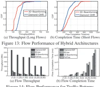
Performance of hybrid architecture. Consider the original traffic as long flows. We add another 200 ran-dom short flows (whose average size is one tenth that of the original traffic) to study the performance of mixed flows in hybrid architectures. In Fig. 13a, the through-put of long flows in Diamond-OHR is higher than that of 3D-beamforming. The number of long flows whose throughput is larger than 225Mbps takes above 90% in Diamond, while the number takes less than 40% in 3D-beamforming. Moreover, in Fig. 13b, the maximum completion time of short flows in Diamond is about 25% less than that of 3D-beamforming. In Diamond, a larger number of concurrent wireless links can be supported to increase the transmission capacity, which contributes to both higher throughput for long flows and smaller com-pletion time for short flows.
Performance of load balancing. Following the pri-or wpri-ork [19], we use a unifpri-orm model where flows be-tween pairs of racks arrive independently with a Poisson arrival-rate as the baseline. We also consider the hotspot model [23], where in addition to the uniform baseline, a subset of rack pairs have higher arrival rates and larger flow sizes. We use a tuple(X,Y)to describe the hotspot
traffic model: theX element represents the average flow
0 150 300 450 600 750 900 0 0.2 0.4 0.6 0.8 1 Throughput(Mb/s) CDF p 3D−Beamforming Diamond−OHR
(a) Throughput (Long Flows)
0 200 400 600 800 1000 1200 0 0.2 0.4 0.6 0.8 1
Flow Completion Time(ms)
CDF
3D−Beamforming Diamond−OHR
(b) Completion Time (Short Flows)
Figure 13: Flow Performance of Hybrid Architectures
(1,0) (1,25) (1,50) (5,0) (5,25) (5,50) 0 500 1000 1500 2000 2500 3000 Throughput ( Mb) Diamond-HDF BCube 3D-Beamforming FatTree
(a) Flow Throughput (1,0) (1,25) (1,50) (5,0) (5,25) (5,50)
0 1x10⁴ 2x10⁴ 3x10⁴ 4x10⁴ Flow C omplet ion Time (ms) Diamond-HDF BCube 3D-Beamforming FatTree
(b) Flow Completion Time
Figure 14: Flow Performance for Traffic Patterns size, where 1 denotes the average flow size is 100MB, and 5 corresponds to 500MB; theY element denotes the percentage of the number of hot nodes.
As Fig. 14 shows, the flow performance of the four topologies deteriorates as expected when increas-ing the average flow size and the number of hot n-odes. Diamond-HDF performs the best, providing the largest flow throughput and lowest flow completion time. Benefited from the rich server-level wireless links, the throughput of Diamond is about 5 times that of oth-er topologies in the lightest traffic case (1,0), and 9
times that of the other topologies in the worst traffic case
(5,50). Correspondingly, the flow completion time of
Diamond is about 70% lower than that of other topolo-gies. This demonstrates the high performance gains of Diamond-HDF and its capability of effectively balanc-ing the load upon heavy traffic.
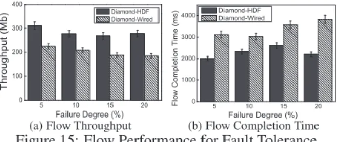
Performance of fault tolerance. In Fig. 15, we evaluate the flow performance of Diamond-HDF and Diamond-Wired when different percentages of nodes fail. To ensure that every flow can be routed under the n-ode failures, we first randomly disable certain percentage of nodes and then randomly generate 100 flows to trans-mit for the remaining nodes. As Fig. 15 shows, the flow throughput of both the HDF and Diamond-Wired decreases with the increasing node failure ratio. However, the flow throughout of Diamond-HDF decreas-es much slower than that of Diamond-Wired. Consider-ing the failure ratio from 0% to 20%, the flow throughput of HDF decreases about 13% while Diamond-Wired decreases about 28%. This illustrates the grace-ful performance degradation of Diamond-HDF for node failures. Similar trends on flow completion time can be found in Fig. 15b.
Performance of wireless reconfiguration. In Table 2, we compare the computation delay and performance of the greedy solution HDF in Diamond with the optimal
5 10 15 20 0 100 200 300 400 Throughput (Mb) Failure Degree (%) Diamond-HDF Diamond-Wired
(a) Flow Throughput
5 10 15 20 0 1000 2000 3000 4000
Flow Completion Time (ms)
Failure Degree (%)
Diamond-HDF Diamond-Wired
(b) Flow Completion Time
Figure 15: Flow Performance for Fault Tolerance solution (named Full-ILP) of the HLBP problem. We use the ILP solver LINGO to compute the global optimal solution of ILP for routing (we obtained the same result-s when uresult-sing the ILP toolbox in MATLAB for calcula-tion). Limited by the memory constraint of LINGO, we evaluate the scales of Diamond with up to 5 rings which contains totally 60 racks and each rack holds 48 server-s. We can see that the computation delay of Full-ILP increases quickly with the number of rings while HDF keeps a stable and low computation delay around 30m-s. The tradeoff is HDF gets up to 15% gap on the per-formance of throughput and flow completion time when compared with Full-ILP. For a practical network scale within 20 rings, Full-ILP can not provide the solution in reasonable time, while HDF still achieves a low de-lay within 100ms, which is comparable to the feasible scheduling overhead illustrated in [4].
8 Related Work
Conventional data center: There exist prevalent hot spots in hierarchical data centers [3, 15, 18, 39], which limits the DCN performance. Many DCN architectures have been proposed to address the hot-spot problem in tree-based data center networks. Some efforts [30–32] propose to construct a random networking topology to achieve smaller network diameter, less hot spots and higher performance than state-of-art structured architec-tures. But the wiring and routing are quite challenging in a totally random wired network. In [16, 17], authors propose to build the network recursively to efficiently e-liminate the structured bottleneck. However, the routing is restricted to follow its recursive structure, which does not consider the high dynamics in traffic demands and thus may lead to more hot spots.
Hybrid data center networking:Recent efforts turn to hybrid data center networking with flexible new net-working components (e.g., the optical circuit switches, 60GHz wireless radios or FSO transceivers) to address the dynamic traffic demands [13,18,19,24,25,28,33,38].
Table 2: Performance of reconfiguration
Ring Delay (ms) Throughput Flow Completion Time # Full-ILP HDF Gap Gap
2 219 15 0.08 0.11
3 313 31 0.08 0.15
4 625 31 0.12 0.01
5 11625 32 0.15 0.15
Flyway first illustrates the feasibility of applying 60GHz wireless technology in DCNs [18]. The work in [38] further enhances the Flyway performance by using the ceiling reflector to bounce signals to avoid blocking on the 2D plane. Using the same method, Firefly explores the feasibility of running free-space-optical (FSO) trans-missions in DCNs [19]. This method, however, requires a height-restricted ceiling and also complete clearance above racks, which is infeasible in most data centers due to the existence of air conditioning pipes and steel struc-tures above the racks [1]. Moreover, existing methods only considered the local performance improvement at the rack level and part of network layers. In contrast, Diamond can run a larger number of network-wide wire-less links (either 60GHz or FSO) without involving any engineering efforts to change the room plan above racks. Both wireless technologies can be applied in Diamond at the server level with different trade-offs: commodity 60GHz antenna is much cheaper and smaller than FSO transceivers while FSO has little interference footprint and longer transmission distance. With the decreasing cost of optical transceivers, FSO shows great promise to run in Diamond in the future.
9 Conclusion
We propose Diamond, a novel hybrid network architec-ture, to enable high capacity and seamless data transmis-sions over both wired and wireless network links. Specif-ically, we introduce the concept of Ring Reflection Space (RRS) to enable the wide deployment of wireless radios at servers and high number of concurrent wireless trans-missions through low-cost multi-reflection over the met-al, and develop a precise reflection scheme to reduce the wireless interference inside an RRS. The rich wireless re-sources allow Diamond to flexibly configure the network topology and form the transmission path to avoid cre-ating hot traffic spots while enabling transmissions over random network topology for low delay. We also prove the scalability of the proposed architecture. We imple-ment the proposed techniques over 60Ghz testbed and demonstrate its functionality. Our results from extensive simulations show that the cohesive structure of Diamond enables fine-grained and network-wide load balancing, effective routing and graceful fault-tolerance.
Acknowledgments
This work is supported by National Natural Science Foundation of China (no. 61120106008, 61422206), Ts-inghua National Laboratory for Information Science and Technology (TNList). Xin Wang’s research is support-ed by NSF CNS 1526843, and Xiangyang Li’s research is supported by NSF ECCS-1247944. We would like to thank our shepherd Alex C. Snoeren and the anonymous reviewers for their valuable feedback and suggestions.
References
[1] Google data center image. http://www.google.com/about/ datacenters/gallery/#/all.
[2] ABU-LIBDEH, H., COSTA, P., ROWSTRON, A., O’SHEA, G.,
ANDDONNELLY, A. Symbiotic routing in future data centers. In
SIGCOMM(2011).
[3] AL-FARES, M., LOUKISSAS, A., ANDVAHDAT, A. A scal-able, commodity data center network architecture. InSIGCOMM
(2008).
[4] AL-FARES, M., RADHAKRISHNAN, S., RAGHAVAN, B., HUANG, N.,ANDVAHDAT, A. Hedera: Dynamic flow
schedul-ing for data center networks. InNSDI(2010).
[5] ALIZADEH, M., GREENBERG, A., MALTZ, D. A., PADHYE, J., PATEL, P., PRABHAKAR, B., SENGUPTA, S.,ANDSRIDHA -RAN, M. Data center tcp (dctcp). InSIGCOMM(2011). [6] BASU, A.,ANDRIECKE, J. Stability issues in ospf routing. In
SIGCOMM(2001).
[7] BENSON, T., AKELLA, A.,ANDMALTZ, D. A. Network traffic characteristics of data centers in the wild. InIMC(2010). [8] BENSON, T., ANAND, A., AKELLA, A.,ANDZHANG, M.
Un-derstanding data center traffic characteristics. ACM SIGCOMM
Computer Communication Review 40, 1 (2010), 92–99.
[9] CHEN, K., SINGLA, A., SINGH, A., RAMACHANDRAN, K.,
X-U, L., ZHANG, Y., WEN, X.,ANDCHEN, Y. Osa: an optical switching architecture for data center networks with unprecedent-ed flexibility. InNSDI(2012).
[10] CUI, Y., WANG, H., CHENG, X., LI, D.,ANDYLA¨-J ¨AASKI¨ , A. Dynamic scheduling for wireless data center networks.IEEE
Transactions on Parallel and Distributed Systems (TPDS) 24, 12
(2013), 2365–2374.
[11] CURTIS, A. R., MOGUL, J. C., TOURRILHES, J., YALAGAN
-DULA, P., SHARMA, P.,ANDBANERJEE, S. Devoflow: scaling flow management for high-performance networks. InSIGCOMM
(2011).
[12] DE BRUIJN, N. G., ANDERDOS, P. A combinatorial
prob-lem. Koninklijke Nederlandse Akademie v. Wetenschappen 49,
49 (1946), 758–764.
[13] FARRINGTON, N., PORTER, G., RADHAKRISHNAN, S., BAZ
-ZAZ, H. H., SUBRAMANYA, V., FAINMAN, Y., PAPEN, G.,
ANDVAHDAT, A. Helios: a hybrid electrical/optical switch
ar-chitecture for modular data centers. InSIGCOMM(2011). [14] GAREY, M. R., AND JOHNSON, D. S. Computers and
in-tractability: A guide to the theory of np-completeness.WH
Free-man & Co., San Francisco(1979), 61–62.
[15] GREENBERG, A., HAMILTON, J. R., JAIN, N., KANDULA, S., KIM, C., LAHIRI, P., MALTZ, D. A., PATEL, P.,ANDSEN -GUPTA, S. Vl2: a scalable and flexible data center network. In
SIGCOMM(2009).
[16] GUO, C., LU, G., LI, D., WU, H., ZHANG, X., SHI, Y., TIAN, C., ZHANG, Y.,ANDLU, S. Bcube: a high performance,
server-centric network architecture for modular data centers. In SIG-COMM(2009).
[17] GUO, C., WU, H., TAN, K., SHI, L., ZHANG, Y., ANDLU,
S. Dcell: a scalable and fault-tolerant network structure for data centers. InSIGCOMM(2008).
[18] HALPERIN, D., KANDULA, S., PADHYE, J., BAHL, P.,AND
WETHERALL, D. Augmenting data center networks with multi-gigabit wireless links. InSIGCOMM(2011).
[19] HAMEDAZIMI, N., QAZI, Z., GUPTA, H., SEKAR, V., DAS,
S. R., LONGTIN, J. P., SHAH, H.,ANDTANWER, A. Firefly: a reconfigurable wireless data center fabric using free-space optics.
InSIGCOMM(2014).
[20] KANDULA, S., SENGUPTA, S., GREENBERG, A., PATEL, P.,
ANDCHAIKEN, R. The nature of data center traffic: measure-ments & analysis. InSIGCOMM(2009).
[21] LI, X.-Y. Multicast capacity of wireless ad hoc networks.
IEEE/ACM Transactions on Networking (TON) 17, 3 (2009),
950–961.
[22] LI, X.-Y., TANG, S.-J.,ANDFRIEDER, O. Multicast capacity
for large scale wireless ad hoc networks. InMOBICOM(2007). [23] LI, X.-Y.,ANDWANG, Y. Simple approximation algorithms and
ptass for various problems in wireless ad hoc networks.Journal
of Parallel and Distributed Computing 66, 4 (2006), 515–530.
[24] LIU, H., LU, F., FORENCICH, A., KAPOOR, R., TEWARI, M., VOELKER, G. M., PAPEN, G., SNOEREN, A. C.,ANDPORTER, G. Circuit switching under the radar with reactor. InNSDI
(2014).
[25] LIU, Y. J., GAO, P. X., WONG, B.,ANDKESHAV, S. Quartz: a new design element for low-latency dcns. InSIGCOMM(2014). [26] MCKEOWN, N., ANDERSON, T., BALAKRISHNAN, H., PARULKAR, G., PETERSON, L., REXFORD, J., SHENKER, S., ANDTURNER, J. Openflow: enabling innovation in campus net-works. ACM SIGCOMM Computer Communication Review 38, 2 (2008), 69–74.
[27] PERRY, J., OUSTERHOUT, A., BALAKRISHNAN, H., SHAH, D.,
ANDFUGAL, H. Fastpass: A centralized zero-queue datacenter network. InSIGCOMM(2014).
[28] PORTER, G., STRONG, R., FARRINGTON, N., FORENCICH, A., CHEN-SUN, P., ROSING, T., FAINMAN, Y., PAPEN, G.,AND
VAHDAT, A. Integrating microsecond circuit switching into the data center. InSIGCOMM(2013).
[29] SHIN, J.-Y., SIRER, E. G., WEATHERSPOON, H., AND
KIROVSKI, D. On the feasibility of completely wirelesss dat-acenters. IEEE/ACM Transactions on Networking (TON) 21, 5 (2013), 1666–1679.
[30] SHIN, J.-Y., WONG, B.,ANDSIRER, E. G. Small-world dat-acenters. InProceedings of the 2nd ACM Symposium on Cloud
Computing(2011), ACM, p. 2.
[31] SINGLA, A., GODFREY, P. B.,ANDKOLLA, A. High through-put data center topology design. InNSDI(2014).
[32] SINGLA, A., HONG, C.-Y., POPA, L.,ANDGODFREY, P. B.
Jellyfish: Networking data centers randomly. InNSDI(2012). [33] WANG, G., ANDERSEN, D. G., KAMINSKY, M., PAPAGIAN
-NAKI, K., NG, T., KOZUCH, M.,ANDRYAN, M. c-through: Part-time optics in data centers. InSIGCOMM(2010). [34] WANG, W., WANG, Y., LI, X.-Y., SONG, W.-Z., AND
FRIEDER, O. Efficient interference-aware tdma link scheduling for static wireless networks. InMOBICOM(2006).
[35] WANG, Y., WANG, W., LI, X.-Y., AND SONG, W.-Z. Interference-aware joint routing and tdma link scheduling for static wireless networks.IEEE Transactions on Parallel and
Dis-tributed Systems (TPDS) 19, 12 (2008), 1709–1726.
[36] XU, X., LI, X.-Y., WAN, P.-J., AND TANG, S.
Efficien-t scheduling for periodic aggregaEfficien-tion queries in mulEfficien-tihop sensor networks. IEEE/ACM Transactions on Networking (TON) 20, 3 (2012), 690–698.
[37] YU, M., GREENBERG, A. G., MALTZ, D. A., REXFORD, J., YUAN, L., KANDULA, S.,ANDKIM, C. Profiling network per-formance for multi-tier data center applications. InNSDI(2011). [38] ZHOU, X., ZHANG, Z., ZHU, Y., LI, Y., KUMAR, S., VAHDAT, A., ZHAO, B. Y.,ANDZHENG, H. Mirror mirror on the ceiling: flexible wireless links for data centers. InSIGCOMM(2012). [39] ZHU, Y., ZHOU, X., ZHANG, Z., ZHOU, L., VAHDAT, A.,
ZHAO, B. Y.,ANDZHENG, H. Cutting the cord: a robust

![Figure 6: Path length ratio of different topologies There are some existing studies [21–23, 34–36] on find-ing an approximate IS solution in some special interfer-ence graphs](https://thumb-us.123doks.com/thumbv2/123dok_us/946926.2623272/7.918.132.418.109.232/figure-different-topologies-existing-studies-approximate-solution-interfer.webp)