ibm.com/redbooks
Introduction to Storage
Area Networks
Jon Tate
Fabiano Lucchese
Richard Moore
Learn basic SAN terminology and
component uses
Introduce yourself to the benefits a
SAN can bring
Discover the IBM
TotalStorage SAN portfolio
Introduction to Storage Area Networks
July 2006
International Technical Support Organization
Fourth Edition (July 2006)
This edition applies to the IBM TotalStorage portfolio.
Note: Before using this information and the product it supports, read the information in “Notices” on page xv.
© Copyright IBM Corp. 1999, 2003, 2006. All rights reserved. iii
Contents
Figures . . . xi Notices . . . xv Trademarks . . . xvi Preface . . . xviiThe team that wrote this redbook. . . xviii
Become a published author . . . xix
Comments welcome . . . xx
Chapter 1. Introduction . . . 1
1.1 What is a Storage Area Network? . . . 2
1.2 SAN components . . . 4
1.2.1 SAN connectivity . . . 5
1.2.2 SAN storage . . . 5
1.2.3 SAN servers . . . 6
1.3 The importance of standards. . . 6
1.4 Where are SANs heading? . . . 7
Chapter 2. How, and why, can we use a SAN? . . . 9
2.1 Why use a SAN? . . . 10
2.1.1 The problem . . . 10
2.1.2 The requirements . . . 12
2.2 How can we use a SAN?. . . 13
2.2.1 Infrastructure simplification . . . 13
2.2.2 Information lifecycle management . . . 14
2.2.3 Business continuity . . . 15
2.3 Using the SAN components . . . 15
2.3.1 Storage . . . 15
2.3.2 SAN connectivity . . . 17
2.3.3 Servers . . . 21
2.3.4 Putting the components together . . . 26
Chapter 3. Fibre Channel internals . . . 29
3.1 Firstly, why the Fibre Channel architecture? . . . 30
3.1.1 The SCSI legacy . . . 30
3.1.2 Why Fibre Channel? . . . 33
3.2 Layers . . . 36
3.3.1 Attenuation . . . 39
3.3.2 Maximum power . . . 40
3.3.3 Fiber in the SAN . . . 41
3.3.4 Dark fiber. . . 43 3.4 Classes of service . . . 44 3.4.1 Class 1 . . . 44 3.4.2 Class 2 . . . 44 3.4.3 Class 3 . . . 44 3.4.4 Class 4 . . . 45 3.4.5 Class 5 . . . 45 3.4.6 Class 6 . . . 45 3.4.7 Class F . . . 45
3.5 Fibre Channel data movement . . . 46
3.5.1 Byte encoding schemes . . . 46
3.6 Data transport . . . 50
3.6.1 Ordered set . . . 50
3.6.2 Frames . . . 51
3.6.3 Sequences . . . 54
3.6.4 Exchanges . . . 54
3.6.5 In order and out of order . . . 54
3.6.6 Latency . . . 55
3.6.7 Open Fiber Control . . . 55
3.7 Flow control . . . 56
3.7.1 Buffer to buffer . . . 56
3.7.2 End to end . . . 56
3.7.3 Controlling the flow . . . 56
3.7.4 Performance . . . 57
3.8 Addressing . . . 57
3.8.1 World Wide Name . . . 58
3.8.2 Port address . . . 59
3.8.3 24-bit port address . . . 60
3.8.4 Loop address . . . 62
3.8.5 FICON address . . . 62
Chapter 4. Topologies and other fabric services . . . 69
4.1 Fibre Channel topologies . . . 70
4.1.1 Point-to-point . . . 71
4.1.2 Arbitrated loop . . . 72
4.1.3 Switched fabric . . . 73
4.2 Port types . . . 74
4.2.1 Domain ID . . . 76
4.3 Fibre Channel Arbitrated Loop protocols. . . 76
Contents v
4.3.2 Loop addressing . . . 77
4.4 Fibre Channel login . . . 78
4.4.1 Port login . . . 78
4.4.2 Process login. . . 78
4.4.3 Fabric login . . . 79
4.5 Fibre Channel fabric services . . . 79
4.5.1 Management services . . . 80
4.5.2 Time services . . . 80
4.5.3 Simple name server . . . 80
4.5.4 Login services . . . 80
4.5.5 Registered State Change Notification . . . 80
4.6 Routing mechanisms . . . 80
4.6.1 Spanning tree . . . 81
4.6.2 Fabric shortest path first . . . 81
4.7 Zoning . . . 82
4.7.1 Hardware zoning . . . 84
4.7.2 Software zoning . . . 87
4.7.3 LUN masking. . . 89
Chapter 5. IP storage networking . . . 91
5.1 Fibre Channel over IP . . . 91
5.2 iFCP . . . 92
5.3 iSCSI . . . 93
5.4 The FCIP, iFCP or iSCSI conundrum . . . 93
5.5 The multiprotocol environment . . . 94
5.5.1 Fibre Channel switching . . . 94
5.5.2 Fibre Channel routing . . . 94
5.5.3 Tunneling . . . 95
5.5.4 Routers and gateways . . . 95
5.5.5 Internet Storage Name Service . . . 95
5.6 Deeper into the protocols . . . 95
5.6.1 FCIP . . . 96 5.6.2 iFCP . . . 97 5.6.3 iSCSI . . . 98 5.7 Routing considerations . . . 100 5.7.1 Packet size . . . 100 5.7.2 TCP congestion control . . . 101 5.7.3 Round-trip delay . . . 101 5.7.4 Write acceleration . . . 103 5.7.5 Tape acceleration . . . 105
5.8 Multiprotocol solution briefs . . . 107
5.8.1 Dividing a fabric into sub-fabrics . . . 107
5.8.3 Connecting hosts using iSCSI. . . 108
Chapter 6. Fibre Channel products and technology . . . 109
6.1 The environment . . . 110
6.2 SAN devices . . . 110
6.2.1 Bridges and gateways . . . 111
6.2.2 Arbitrated loop hubs . . . 112
6.2.3 Switched hubs . . . 112
6.2.4 Switches and directors . . . 112
6.2.5 Multiprotocol routing . . . 113
6.2.6 Service modules . . . 113
6.2.7 Multiplexers . . . 114
6.2.8 Storage considered as legacy . . . 114
6.3 Componentry. . . 114
6.3.1 ASIC . . . 114
6.3.2 Fibre Channel transmission rates . . . 115
6.3.3 SerDes . . . 115
6.3.4 Backplane and blades . . . 115
6.4 Gigabit transport technology . . . 115
6.4.1 Ten Gigabit small form-factor pluggable . . . 116
6.4.2 Small form-factor pluggable media . . . 116
6.4.3 Gigabit interface converters . . . 117
6.4.4 Gigabit Link Modules. . . 118
6.4.5 Media Interface Adapters . . . 119
6.4.6 1x9 Transceivers . . . 120
6.4.7 Host bus adapters . . . 120
6.5 Inter-switch links . . . 121
6.5.1 Cascading . . . 122
6.5.2 Hops . . . 122
6.5.3 Fabric shortest path first . . . 123
6.5.4 Blocking. . . 125 6.5.5 Latency . . . 126 6.5.6 Oversubscription . . . 126 6.5.7 Congestion . . . 126 6.5.8 Trunking . . . 126 Chapter 7. Management . . . 129 7.1 Management principles . . . 130 7.1.1 Management types . . . 130
7.1.2 SAN management levels. . . 132
7.1.3 SAN fault isolation and troubleshooting . . . 134
7.2 Management interfaces and protocols . . . 134
Contents vii
7.2.2 Simple Network Management Protocol . . . 137
7.2.3 Service Location Protocol . . . 138
7.2.4 Vendor-specific mechanisms . . . 139
7.3 Management features . . . 141
7.3.1 IBM TotalStorage Productivity Center . . . 141
7.4 Vendor management applications . . . 144
7.4.1 IBM TotalStorage b-type family . . . 144
7.4.2 Cisco . . . 144
7.4.3 IBM TotalStorage e-type family . . . 145
7.4.4 IBM TotalStorage m-type family . . . 145
7.5 SAN multipathing software . . . 146
7.6 Storage virtualization in the SAN. . . 149
7.6.1 SANs and storage virtualization . . . 149
7.6.2 Virtualization levels . . . 150 7.6.3 Virtualization models . . . 151 7.6.4 Virtualization strategies . . . 152 Chapter 8. Security . . . 155 8.1 Security principles . . . 157 8.1.1 Access control . . . 157
8.1.2 Auditing and accounting . . . 157
8.1.3 Data security . . . 157
8.1.4 Encryption . . . 158
8.1.5 Encryption schemes . . . 162
8.1.6 Encryption tools and systems . . . 163
8.2 Security mechanisms . . . 165
8.2.1 IP security . . . 165
8.3 Fibre Channel security . . . 166
8.3.1 Securing a fabric . . . 166
8.3.2 Zoning, masking and binding . . . 171
8.3.3 Data security . . . 172
8.4 Best practices . . . 173
Chapter 9. The IBM product portfolio . . . 175
9.1 Why an IBM TotalStorage SAN? . . . 176
9.2 Entry SAN switches . . . 176
9.2.1 IBM System Storage SAN10Q . . . 176
9.2.2 IBM TotalStorage SAN16B-2 . . . 177
9.2.3 IBM TotalStorage SAN16M-2 . . . 180
9.3 Midrange SAN switches . . . 183
9.3.1 IBM TotalStorage SAN32B-2 . . . 183
9.3.2 IBM System Storage SAN64B-2 . . . 185
9.3.4 Cisco MDS 9120 and 9140 Multilayer Fabric Switch . . . 189
9.3.5 Cisco MDS 9216i and 9216A Multilayer Fabric Switch . . . 190
9.3.6 Cisco MDS 9020 Fabric Switch. . . 192
9.4 Enterprise SAN directors . . . 193
9.4.1 IBM TotalStorage SAN Director M14 . . . 194
9.4.2 IBM TotalStorage SAN140M . . . 196
9.4.3 IBM TotalStorage SANC40M . . . 198
9.4.4 IBM TotalStorage SAN256M . . . 199
9.4.5 IBM TotalStorage SAN256B . . . 201
9.4.6 Cisco MDS 9506 Multilayer Director . . . 203
9.4.7 Cisco MDS 9509 Multilayer Director . . . 205
9.4.8 Cisco MDS 9513 Multilayer Director . . . 206
9.5 Multiprotocol routers . . . 208
9.5.1 IBM TotalStorage SAN04M-R multiprotocol SAN router . . . 208
9.5.2 IBM TotalStorage SAN 16B-R multiprotocol SAN router . . . 210
9.5.3 IBM TotalStorage SAN16M-R multiprotocol SAN router . . . 211
9.5.4 IBM System Storage SAN18B-R multiprotocol router . . . 212
9.6 IBM TotalStorage DS family . . . 213
9.6.1 Entry-level disk systems . . . 214
9.6.2 IBM TotalStorage DR550 Express . . . 216
9.6.3 IBM TotalStorage EXP24 . . . 217
9.6.4 Mid-range disk systems . . . 218
9.6.5 IBM System Storage DR550 . . . 224
9.6.6 Enterprise disk systems . . . 225
9.7 IBM Tape Storage Systems . . . 230
9.7.1 Tape drives . . . 235
9.8 IBM TotalStorage virtualization . . . 245
9.8.1 IBM TotalStorage SAN Volume Controller . . . 245
9.8.2 IBM TotalStorage SAN File System . . . 246
Chapter 10. Solutions . . . 249
10.1 Introduction . . . 250
10.2 Basic solution principles . . . 250
10.2.1 Connectivity. . . 250
10.2.2 Adding capacity . . . 251
10.2.3 Data movement and copy . . . 251
10.2.4 Upgrading to faster speeds . . . 252
10.3 Infrastructure simplification . . . 253 10.3.1 Storage pooling . . . 253 10.3.2 Data sharing . . . 256 10.3.3 Clustering . . . 261 10.3.4 Consolidation . . . 262 10.4 Business continuity . . . 264
Contents ix
10.4.1 LAN-free data movement . . . 265
10.4.2 Server-free data movement . . . 267
10.4.3 Disaster backup and recovery. . . 269
10.5 Information lifecycle management. . . 270
10.5.1 ILM elements. . . 270
10.5.2 Tiered storage management . . . 270
10.5.3 Long-term data retention . . . 273
10.5.4 Data lifecycle management . . . 274
10.5.5 Policy-based archive management . . . 275
Appendix A. SAN standards and organizations . . . 279
Storage Networking Industry Association. . . 281
Fibre Channel Industry Association . . . 281
SCSI Trade Association . . . 282
International Committee for Information Technology Standards . . . 282
INCITS Technical Committee T11 . . . 282
Information Storage Industry Consortium. . . 283
Internet Engineering Task Force . . . 283
American National Standards Institute . . . 283
Institute of Electrical and Electronics Engineers . . . 284
Distributed Management Task Force . . . 284
Glossary . . . 285
Related publications . . . 309
IBM Redbooks . . . 309
Referenced Web sites . . . 310
How to get IBM Redbooks . . . 311
Help from IBM . . . 311
© Copyright IBM Corp. 1999, 2003, 2006. All rights reserved. xi
Figures
1-1 A SAN . . . 3
1-2 SAN components . . . 5
2-1 The evolution of storage architecture. . . 10
2-2 Disk and tape storage consolidation . . . 14
2-3 Processor-to-storage interface connections . . . 22
2-4 pSeries processor-to-storage interconnections . . . 23
2-5 iSeries hardware design . . . 24
2-6 OS/400 versus NT or UNIX storage addressing . . . 25
2-7 Hardware and operating systems differences . . . 27
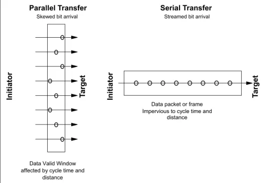
3-1 SCSI Propagation delay results in skew . . . 31
3-2 SCSI bus distance limitations . . . 32
3-3 Multi-drop bus structure . . . 32
3-4 Parallel data transfers versus serial data transfers . . . 34
3-5 Upper and physical layers . . . 36
3-6 Cable types . . . 42
3-7 8b/10b encoding logic . . . 47
3-8 Fibre Channel frame structure . . . 52
3-9 World Wide Name addressing scheme . . . 59
3-10 Fabric port address . . . 61
3-11 FICON port addressing . . . 63
3-12 FICON single switch: Switched point-to-point link address . . . 64
3-13 FICON addressing for cascaded directors . . . 66
3-14 Two cascaded director FICON addressing . . . 67
4-1 The SAN . . . 70
4-2 Point-to-point . . . 72
4-3 Arbitrated loop . . . 73
4-4 Sample switched fabric configuration . . . 74
4-5 Fibre Channel port types . . . 76
4-6 Zoning . . . 83
4-7 An example of zoning . . . 84
4-8 Zoning based on the switch port number . . . 85
4-9 Hardware zoning . . . 86
4-10 Zoning based on the devices’ WWNs . . . 88
5-1 FCIP encapsulates the Fibre Channel frame into IP packets . . . 96
5-2 iFCP encapsulation and header mapping . . . 97
5-3 iSCSI packet format . . . 99
5-4 A standard write request . . . 104
5-6 Tape acceleration example . . . 106
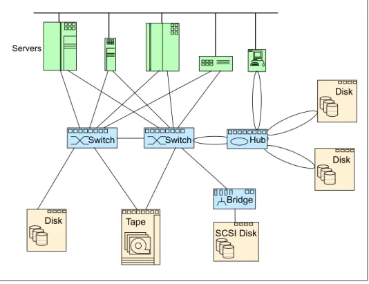
6-1 High-level view of a fabric . . . 111
6-2 SFP . . . 117 6-3 GBIC . . . 118 6-4 GLM . . . 119 6-5 MIA. . . 119 6-6 1x9 transceivers . . . 120 6-7 HBA . . . 121
6-8 Kangaroo illustrating hops in a cascaded fabric . . . 123
6-9 Four-switch fabric. . . 124
6-10 Non-blocking and blocking switching . . . 125
6-11 Trunking . . . 127
7-1 In-band and out-of-band models . . . 131
7-2 SAN management levels . . . 133
7-3 CIMOM component structure . . . 137
7-4 Core-edge SAN environment . . . 147
7-5 Core-edge SAN environment details . . . 148
7-6 Levels that storage virtualization can be applied at . . . 150
8-1 Symmetric and asymmetric cryptography . . . 159
8-2 Securing a message using asymmetric cryptography . . . 160
8-3 Digital signing. . . 161
8-4 Zoning based on the switch port number . . . 169
8-5 Zoning based on the device’s WWN . . . 170
9-1 SAN10Q . . . 177
9-2 SAN16B-2 . . . 178
9-3 SAN16M-2 fabric switch. . . 180
9-4 SAN32B-2 . . . 183
9-5 The IBM System Storage SAN64B-2 . . . 185
9-6 The IBM TotalStorage SAN32M-2 Fabric switch . . . 186
9-7 9120 . . . 189
9-8 9140 . . . 189
9-9 9216i . . . 190
9-10 9216A. . . 191
9-11 Cisco MDS 9020 Fabric Switch . . . 192
9-12 M14 . . . 194
9-13 SAN140M. . . 197
9-14 SAN256M. . . 200
9-15 IBM TotalStorage SAN256B . . . 202
9-16 9506 . . . 205
9-17 9509 . . . 206
9-18 Cisco MDS 9513 Multilayer Director . . . 208
9-19 IBM TotalStorage SAN04M-R multiprotocol SAN router . . . 209
Figures xiii
9-21 SAN16M-R . . . 211
9-22 IBM System Storage SAN18B-R router . . . 212
10-1 Disk pooling . . . 254
10-2 Tape pooling . . . 256
10-3 Logical volume partitioning . . . 258
10-4 File pooling. . . 259
10-5 Homogeneous data sharing . . . 260
10-6 Heterogeneous data sharing . . . 261
10-7 Server clustering . . . 262
10-8 SAN consolidation . . . 263
10-9 LAN-less backup and recovery . . . 266
10-10 Server-free data movement for backup and recovery . . . 267
10-11 Server-free data movement for tape reclamation . . . 268
10-12 Disaster backup and recovery . . . 269
10-13 Traditional non-tiered storage environment . . . 271
10-14 ILM tiered storage environment . . . 272
10-15 ILM policies . . . 275
© Copyright IBM Corp. 1999, 2003, 2006. All rights reserved. xv
Notices
This information was developed for products and services offered in the U.S.A.
IBM may not offer the products, services, or features discussed in this document in other countries. Consult your local IBM representative for information on the products and services currently available in your area. Any reference to an IBM product, program, or service is not intended to state or imply that only that IBM product, program, or service may be used. Any functionally equivalent product, program, or service that does not infringe any IBM intellectual property right may be used instead. However, it is the user's responsibility to evaluate and verify the operation of any non-IBM product, program, or service.
IBM may have patents or pending patent applications covering subject matter described in this document. The furnishing of this document does not give you any license to these patents. You can send license inquiries, in writing, to:
IBM Director of Licensing, IBM Corporation, North Castle Drive Armonk, NY 10504-1785 U.S.A.
The following paragraph does not apply to the United Kingdom or any other country where such provisions are inconsistent with local law: INTERNATIONAL BUSINESS MACHINES CORPORATION PROVIDES
THIS PUBLICATION "AS IS" WITHOUT WARRANTY OF ANY KIND, EITHER EXPRESS OR IMPLIED, INCLUDING, BUT NOT LIMITED TO, THE IMPLIED WARRANTIES OF NON-INFRINGEMENT,
MERCHANTABILITY OR FITNESS FOR A PARTICULAR PURPOSE. Some states do not allow disclaimer of express or implied warranties in certain transactions, therefore, this statement may not apply to you. This information could include technical inaccuracies or typographical errors. Changes are periodically made to the information herein; these changes will be incorporated in new editions of the publication. IBM may make improvements and/or changes in the product(s) and/or the program(s) described in this publication at any time without notice.
Any references in this information to non-IBM Web sites are provided for convenience only and do not in any manner serve as an endorsement of those Web sites. The materials at those Web sites are not part of the materials for this IBM product and use of those Web sites is at your own risk.
IBM may use or distribute any of the information you supply in any way it believes appropriate without incurring any obligation to you.
Information concerning non-IBM products was obtained from the suppliers of those products, their published announcements or other publicly available sources. IBM has not tested those products and cannot confirm the accuracy of performance, compatibility or any other claims related to non-IBM products. Questions on the capabilities of non-IBM products should be addressed to the suppliers of those products.
This information contains examples of data and reports used in daily business operations. To illustrate them as completely as possible, the examples include the names of individuals, companies, brands, and products. All of these names are fictitious and any similarity to the names and addresses used by an actual business enterprise is entirely coincidental.
COPYRIGHT LICENSE:
This information contains sample application programs in source language, which illustrates programming techniques on various operating platforms. You may copy, modify, and distribute these sample programs in any form without payment to IBM, for the purposes of developing, using, marketing or distributing application programs conforming to the application programming interface for the operating platform for which the sample programs are written. These examples have not been thoroughly tested under all conditions. IBM, therefore, cannot guarantee or imply reliability, serviceability, or function of these programs. You may copy, modify, and distribute these sample programs in any form without payment to IBM for the purposes of developing, using, marketing, or distributing application programs conforming to IBM's application programming interfaces.
Trademarks
The following terms are trademarks of the International Business Machines Corporation in the United States, other countries, or both:
Eserver® iSeries™ i5/OS® pSeries® xSeries® z/Architecture™ z/OS® z/VM® zSeries® z9™ AFS® AIX 5L™ AIX® AS/400® BladeCenter® Domino® DB2® DS4000™ DS6000™ DS8000™
Enterprise Storage Server® Enterprise Systems Architecture/390® ECKD™ ESCON® FlashCopy® FICON® Geographically Dispersed Parallel Sysplex™ GDPS® HACMP™ Informix® IBM® Lotus® MVS™ Netfinity® OS/390® OS/400® Parallel Sysplex® POWER5™ PR/SM™ Redbooks™ Redbooks (logo) ™ RMF™ RS/6000® S/360™ S/370™ S/390® Storage Tank™ System z9™ System Storage™ System/360™ System/370™ Tivoli® TotalStorage® Virtualization Engine™ VM/ESA® VSE/ESA™
The following terms are trademarks of other companies:
Java, Jini, Solaris, Streamline, Sun, Sun Microsystems, Ultra, and all Java-based trademarks are trademarks of Sun Microsystems, Inc. in the United States, other countries, or both.
Internet Explorer, Microsoft, Windows NT, Windows Server, Windows, and the Windows logo are trademarks of Microsoft Corporation in the United States, other countries, or both.
Intel, Intel logo, Intel Inside logo, and Intel Centrino logo are trademarks or registered trademarks of Intel Corporation or its subsidiaries in the United States, other countries, or both.
UNIX is a registered trademark of The Open Group in the United States and other countries. Linux is a trademark of Linus Torvalds in the United States, other countries, or both.
© Copyright IBM Corp. 1999, 2003, 2006. All rights reserved. xvii
Preface
The plethora of data created by the businesses of today is making storage a strategic investment priority for companies of all sizes. As storage takes precedence, three major initiatives have emerged:
Infrastructure simplification: Consolidation, virtualization, and automated management with IBM® TotalStorage® can help simplify the infrastructure and ensure that an organization meets its business goals.
Information lifecycle management: Managing business data through its lifecycle from conception until disposal in a manner that optimizes storage and access at the lowest cost.
Business continuity: Maintaining access to data at all times, protecting critical business assets, and aligning recovery costs based on business risk and information value.
Storage is no longer an afterthought. Too much is at stake. Companies are searching for more ways to efficiently manage expanding volumes of data, and to make that data accessible throughout the enterprise; this is propelling the move of storage into the network. Also, the increasing complexity of managing large numbers of storage devices and vast amounts of data is driving greater business value into software and services.
With current estimates of the amount of data to be managed and made available increasing at 60 percent per annum, this is where a storage area network (SAN) enters the arena. Simply put, SANs are the leading storage infrastructure for the global economy of today. SANs offer simplified storage management, scalability, flexibility, availability, and improved data access, movement, and backup.
This IBM Redbook gives an introduction to the SAN. It illustrates where SANs are today, who are the main industry organizations and standard bodies active in the SAN world, and it positions an IBM comprehensive, best-of-breed approach of enabling SANs with its products and services. It introduces some of the most commonly encountered terminology and features present in a SAN.
For further reading, and a deeper dive into the SAN world, readers may find the following redbook especially useful to expand their SAN knowledge:
IBM TotalStorage: SAN Product, Design, and Optimization Guide,
The team that wrote this redbook
This redbook was produced by a team of specialists from around the world working at the International Technical Support Organization, San Jose Center. Jon Tate is a Project Manager for IBM TotalStorage SAN Solutions at the International Technical Support Organization, San Jose Center. Before joining the ITSO in 1999, he worked in the IBM Technical Support Center, providing Level 2 support for IBM storage products. Jon has 20 years of experience in storage software and management, services, and support, and is both an IBM Certified IT Specialist, and an IBM SAN Certified Specialist.
Fabiano Lucchese is the Business Director of Sparsi Computing in Grid (http://www.sparsi.com) and works as a Grid computing consultant in a number of nation-wide projects. In 1994, Fabiano was admitted to the Computer
Engineering undergraduate course of the State University of Campinas, Brazil, and in mid-1997, he moved to France to finish his undergraduate studies at the Central School of Lyon. Also in France, he pursued graduate-level studies in Industrial Automation. Back in Brazil, he joined Unisoma Mathematics for Productivity, where he worked as a Software Engineer on the development of image processing and optimization systems. From 2000 to 2002, he joined the Faculty of Electrical and Computer Engineering of the State University of Campinas as a graduate student and acquired a master’s degree in Computer Engineering for developing a task scheduling algorithm for balancing processing loads on heterogeneous grids.
Richard Moore is an IT Architect who works in Technology Integration and Management (TIM) Competency, Integrated Technology Delivery. He joined IBM United Kingdom in 1979 as a Courier/Storeman. He helped to write the IBM Redbook Implementing Snapshot, SG24-2241, and the Redpaper Virtualization
in a SAN, REDP-3633, and holds a software patent for a storage automation
product.
Thanks to the previous authors of the first, second, and third editions of this redbook:
Angelo Bernasconi Rajani Kanth Ravi Kumar Khattar Peter Mescher Mark S. Murphy Kjell E. Nyström Fred Scholten Giulio John Tarella Andre Telles
Preface xix Thanks to the following people for their contributions to this project:
Tom Cady Deanna Polm Sangam Racherla Sokkieng Wang
International Technical Support Organization, San Jose Center
Lisa Dorr David Nowlen Michael Starling Jeremy Stroup
IBM Storage Systems Group
Jim Baldyga Brian Steffler
Brocade Communications Systems
John McKibben
Cisco Systems
Brent Anderson
McDATA Corporation
Tom and Jenny Chang
Garden Inn Hotel, Los Gatos, California
Become a published author
Join us for a two- to six-week residency program! Help write an IBM Redbook dealing with specific products or solutions, while getting hands-on experience with leading-edge technologies. You'll team with IBM technical professionals, Business Partners and/or customers.
Your efforts will help increase product acceptance and customer satisfaction. As a bonus, you'll develop a network of contacts in IBM development labs, and increase your productivity and marketability.
Find out more about the residency program, browse the residency index, and apply online at:
Comments welcome
Your comments are important to us!
We want our Redbooks™ to be as helpful as possible. Send us your comments about this or other Redbooks in one of the following ways:
Use the online Contact us review redbook form found at:
ibm.com/redbooks
Send your comments in an Internet note to:
Mail your comments to:
IBM Corporation, International Technical Support Organization Dept. HYTD Mail Station P099
2455 South Road
© Copyright IBM Corp. 1999, 2003, 2006. All rights reserved. 1
Chapter 1.
Introduction
Computing is based on information. Information is the underlying resource on which all computing processes are based; it is a company asset. Information is stored on storage media, and is accessed by applications executing on a server. Often the information is a unique company asset. Information is created and acquired every second of every day. Information is the currency of business. To ensure that any business delivers the expected results, they must have access to accurate information, and without delay. The management and protection of business information is vital for the availability of business processes.
This chapter introduces the concept of a Storage Area Network, which has been regarded as the ultimate response to all these needs.
1.1 What is a Storage Area Network?
The Storage Network Industry Association (SNIA) defines the SAN as a network whose primary purpose is the transfer of data between computer systems and storage elements. A SAN consists of a communication infrastructure, which provides physical connections; and a management layer, which organizes the connections, storage elements, and computer systems so that data transfer is secure and robust. The term SAN is usually (but not necessarily) identified with block I/O services rather than file access services.
A SAN can also be a storage system consisting of storage elements, storage devices, computer systems, and/or appliances, plus all control software, communicating over a network.
Put in simple terms, a SAN is a specialized, high-speed network attaching servers and storage devices and, for this reason, It is sometimes referred to as “the network behind the servers.” A SAN allows “any-to-any” connection across the network, using interconnect elements such as routers, gateways, hubs, switches and directors. It eliminates the traditional dedicated connection
between a server and storage, and the concept that the server effectively “owns and manages” the storage devices. It also eliminates any restriction to the amount of data that a server can access, currently limited by the number of storage devices attached to the individual server. Instead, a SAN introduces the flexibility of networking to enable one server or many heterogeneous servers to share a common storage utility, which may comprise many storage devices, including disk, tape, and optical storage. Additionally, the storage utility may be located far from the servers that use it.
The SAN can be viewed as an extension to the storage bus concept, which enables storage devices and servers to be interconnected using similar elements as in local area networks (LANs) and wide area networks (WANs): Routers, hubs, switches, directors, and gateways. A SAN can be shared between servers and/or dedicated to one server. It can be local, or can be extended over
geographical distances.
Note: The SNIA definition specifically does not identify the term SAN with Fibre Channel technology. When the term SAN is used in connection with Fibre Channel technology, use of a qualified phrase such as
Fibre Channel
SAN
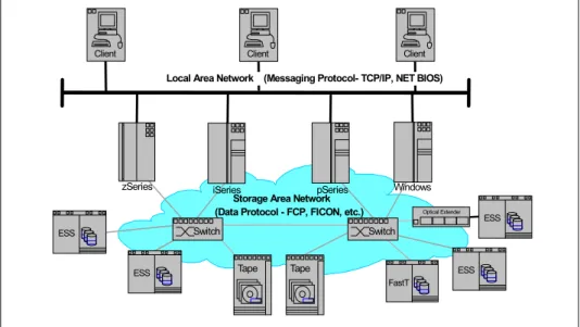
is encouraged. According to this definition, an Ethernet-based network whose primary purpose is to provide access to storage elements would be considered a SAN. SANs are sometimes also used for system interconnection in clusters.Chapter 1. Introduction 3 The diagram in Figure 1-1 shows a tiered overview of a SAN connecting multiple servers to multiple storage systems.
Figure 1-1 A SAN
SANs create new methods of attaching storage to servers. These new methods can enable great improvements in both availability and performance. Today’s SANs are used to connect shared storage arrays and tape libraries to multiple servers, and are used by clustered servers for failover.
A SAN can be used to bypass traditional network bottlenecks. It facilitates direct, high-speed data transfers between servers and storage devices, potentially in any of the following three ways:
Server to storage: This is the traditional model of interaction with storage devices. The advantage is that the same storage device may be accessed serially or concurrently by multiple servers.
Server to server: A SAN may be used for high-speed, high-volume communications between servers.
Storage to storage: This outboard data movement capability enables data to be moved without server intervention, thereby freeing up server processor cycles for other activities like application processing. Examples include a disk device backing up its data to a tape device without server intervention, or remote device mirroring across the SAN.
SANs allow applications that move data to perform better, for example, by having the data sent directly from the source to the target device with minimal server intervention. SANs also enable new network architectures where multiple hosts
C lie n t
C lie n t C lie n t C lie n t C lie n t C lie n t C lie n t N e tw o r k & L A N S z S e r ie s iS e r ie s U N IX p S e r ie s W in d o w s S to r a g e A r e a N e tw o r k Ta p e E S S F a s tT T a p e L ib r.
access multiple storage devices connected to the same network. Using a SAN can potentially offer the following benefits:
Improvements to application availability: Storage is independent of
applications and accessible through multiple data paths for better reliability, availability, and serviceability.
Higher application performance: Storage processing is off-loaded from servers and moved onto a separate network.
Centralized and consolidated storage: Simpler management, scalability, flexibility, and availability.
Data transfer and vaulting to remote sites: Remote copy of data enabled for disaster protection and against malicious attacks.
Simplified centralized management: Single image of storage media simplifies management.
1.2 SAN components
As stated previously, Fibre Channel is the predominant architecture upon which most SAN implementations are built, with FICON® as the standard protocol for z/OS® systems, and FCP as the standard protocol for open systems. The SAN components described in the following sections are Fibre Channel-based, and are shown in Figure 1-2 on page 5.
Chapter 1. Introduction 5
Figure 1-2 SAN components
1.2.1 SAN connectivity
The first element that must be considered in any SAN implementation is the connectivity of storage and server components typically using Fibre Channel. The components listed above have typically been used for LAN and WAN implementations. SANs, like LANs, interconnect the storage interfaces together into many network configurations and across longer distances.
Much of the terminology used for SAN has its origins in IP network terminology. In some cases, the industry and IBM use different terms that mean the same thing, and in some cases, mean different things.
1.2.2 SAN storage
The SAN liberates the storage device so it is not on a particular server bus, and attaches it directly to the network. In other words, storage is externalized and can be functionally distributed across the organization. The SAN also enables the centralization of storage devices and the clustering of servers, which has the potential to make for easier and less expensive centralized administration that lowers the total cost of ownership (TCO).
Storage
Servers
Router Hub Switch Director zSeries Windows iSeries UNIX LINUX pSeries Tape ESS DS Family SSA JBODThe storage infrastructure is the foundation on which information relies, and therefore must support a company’s business objectives and business model. In this environment simply deploying more and faster storage devices is not enough. A SAN infrastructure provides enhanced network availability, data accessibility, and system manageability, and It is important to remember that a good SAN begins with a good design. This is not only a maxim, but must be a philosophy when we design or implement a SAN.
1.2.3 SAN servers
The server infrastructure is the underlying reason for all SAN solutions. This infrastructure includes a mix of server platforms such as Windows®, UNIX® (and its various flavors), and z/OS. With initiatives such as server consolidation and e-business, the need for SANs will increase, making the importance of storage in the network greater.
1.3 The importance of standards
Why do we care about standards? Standards are the starting point for the potential interoperability of devices and software from different vendors in the SAN marketplace. SNIA, among others, defined and ratified the standards for the SANs of today, and will keep defining the standards for tomorrow. All of the players in the SAN industry are using these standards now, as these are the basis for wide acceptance of SANs. Widely accepted standards potentially allow for heterogeneous, cross-platform, multivendor deployment of SAN solutions. As all vendors have accepted these SAN standards, there
should
be no problem in connecting the different vendors into the same SAN network. However, nearly every vendor has an interoperability lab where it tests all kind of combinations between their products and those of other vendors. Some of the most important aspects in these tests are the reliability, error recovery, and performance. If a combination has passed the test, that vendor is going to certify or support this combination.IBM participates in many industry standards organizations that work in the field of SANs. IBM believes that industry standards must be in place, and if necessary, re-defined for SANs to be a major part of the IT business mainstream.
Probably the most important industry standards organization for SANs is the Storage Networking Industry Association (SNIA). IBM is a founding member and board officer in SNIA. SNIA and other standards organizations and IBM
participation are described in Appendix A, “SAN standards and organizations” on page 279.
Chapter 1. Introduction 7
1.4 Where are SANs heading?
Are SANs themselves evolving or are they likely to become extinct? Will they be overtaken by other technology? Certainly reports of the death of SANs have been greatly exaggerated. There has been far too much investment made for SANs to quietly lay down and go the way of the dinosaurs. There is no new “killer application” or technology in the immediate future that is threatening the SAN world. However, there is a gradual evolution that is beginning to pick up pace in the SAN world.
The evolution that is taking place is one of diversity. More and more we are seeing advances in technology find their way into the SAN chassis. What is quickly happening is that SANs are becoming multiprotocol capable. The industry recognizes that it is no longer acceptable to build a solution that will either create SAN islands (in much the same way as islands of information existed), or take an inordinate amount of cabling, support, power, and management.
Rather, the trend towards the simplification of the SAN infrastructure suddenly took a turn for the better. In a single footprint, multiple technologies that were once competing for floor space now happily sit alongside the “competition” in a single chassis. It is not uncommon to see FCIP, iFCP, and iSCSI together these days, and they are working together rather nicely. Most IT vendors also have virtualization solutions that present a single view of storage, and management solutions at the enterprise level. The SAN has quietly become an enabler for many technologies and protocols to share the same arena, without the somewhat tiresome arguments of which is “best.”
© Copyright IBM Corp. 1999, 2003, 2006. All rights reserved. 9
Chapter 2.
How, and why, can we use a
SAN?
In the previous chapter, we introduced the basics by presenting a standard SAN definition, as well as a brief description of the underlying technologies and concepts that are behind a SAN implementation.
In this chapter, we extend this discussion by presenting real-life SAN issues, alongside well-known technologies and platforms used in SAN implementations. We also discuss some of the trends that are driving SAN evolution, and how they may affect the future of storage technology.
2.1 Why use a SAN?
In this section we describe the main motivators that drive SAN implementations, and present some of the key benefits that this technology might bring to
data-dependent business.
2.1.1 The problem
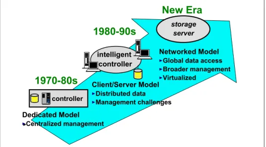
As illustrated in Figure 2-1, the 1990’s witnessed a major shift away from the traditional mainframe, host-centric model of computing to the client/server model. Today, many organizations have hundreds, even thousands, of distributed servers and client systems installed throughout its IT infrastructure. Many of these systems are powerful computers, with more processing capability than many mainframe computers had only a few years ago.
Figure 2-1 The evolution of storage architecture
Storage, for the most part, is directly connected by a dedicated channel to the server it supports. Frequently the servers are interconnected using local area networks (LAN) and wide area networks (WAN), to communicate and exchange data. The amount of disk storage capacity attached to such systems has grown exponentially in recent years. It is commonplace for a desktop personal computer or ThinkPad today to have storage in the order of tens of gigabytes. There has been a move to disk arrays, comprising a number of disk drives. The arrays may be “just a bunch of disks” (JBOD), or various implementations of redundant arrays of independent disks (RAID). The capacity of such arrays may be
1980-90s
1970-80s
New Era
intelligent controller controller storage server Networked ModelGlobal data access Broader management Virtualized Client/Server Model Distributed data Management challenges Dedicated Model Centralized management
Chapter 2. How, and why, can we use a SAN? 11 measured in tens or hundreds of gigabytes, but I/O bandwidth has not kept pace with the rapid growth in processor speeds and disk capacities.
Distributed clients and servers are frequently chosen to meet specific application needs. They may, therefore, run different operating systems (such as Windows NT®, UNIX of differing flavors, Novell NetWare, VMS, and so on), and different database software (for example, DB2®, Oracle, Informix®, SQL Server). Consequently, they have different file systems and different data formats. Managing this multi-platform, multivendor, networked environment has become increasingly complex and costly. Multiple vendor’s software tools, and
appropriately skilled human resources must be maintained to handle data and storage resource management on the many differing systems in the enterprise. Surveys published by industry analysts consistently show that management costs associated with distributed storage are much greater, up to 10 times more, than the cost of managing consolidated or centralized storage. This includes costs of backup, recovery, space management, performance management, and disaster recovery planning.
Disk storage is often purchased from the processor vendor as an integral feature, and it is difficult to establish if the price you pay per gigabyte (GB) is competitive, compared to the market price of disk storage. Disks and tape drives, directly attached to one client or server, cannot be used by other systems, leading to inefficient use of hardware resources. Organizations often find that they have to purchase more storage capacity, even though free capacity is available in other platforms.
Additionally, it is difficult to scale capacity and performance to meet rapidly changing requirements, such as the explosive growth in e-business applications, and the need to manage information over its entire life cycle, from conception to intentional destruction.
Information stored on one system cannot readily be made available to other users, except by creating duplicate copies, and moving the copy to storage that is attached to another server. Movement of large files of data may result in
significant degradation of performance of the LAN/WAN, causing conflicts with mission-critical applications. Multiple copies of the same data may lead to inconsistencies between one copy and another. Data spread on multiple small systems is difficult to coordinate and share for enterprise-wide applications, such as e-business, Enterprise Resource Planning (ERP), Data Warehouse, and Business Intelligence (BI).
Backup and recovery operations across a LAN may also cause serious disruption to normal application traffic. Even using fast Gigabit Ethernet
transport, sustained throughput from a single server to tape is about 25 GB per hour. It would take approximately 12 hours to fully back up a relatively moderate
departmental database of 300 GBs. This may exceed the available window of time in which this must be completed, and it may not be a practical solution if business operations span multiple time zones. It is increasingly evident to IT managers that these characteristics of client/server computing are too costly, and too inefficient. The islands of information resulting from the distributed model of computing do not match the needs of the enterprise.
New ways must be found to control costs, improve efficiency, and simplify the storage infrastructure to meet the requirements of the modern business world.
2.1.2 The requirements
With this scenario in mind, we can think of a number of requirements that today’s storage infrastructures should meet. Some of the most important are:
Unlimited and just-in-time scalability. Businesses require the capability to flexibly adapt to rapidly changing demands for storage resources without performance degradation.
System simplification. Businesses require an easy-to-implement
infrastructure with the minimum of management and maintenance. The more complex the enterprise environment, the more costs are involved in terms of management. Simplifying the infrastructure can save costs and provide a greater return on investment (ROI).
Flexible and heterogeneous connectivity. The storage resource must be able to support whatever platforms are within the IT environment. This is
essentially an investment protection requirement that allows you to configure a storage resource for one set of systems, and subsequently configure part of the capacity to other systems on an as-needed basis.
Security. This requirement guarantees that data from one application or system does not become overlaid or corrupted by other applications or systems. Authorization also requires the ability to fence off one system’s data from other systems.
Availability. This is a requirement that implies both protection against media failure as well as ease of data migration between devices, without interrupting application processing. This certainly implies improvements to backup and recovery processes: attaching disk and tape devices to the same networked infrastructure allows for fast data movement between devices, which provides enhanced backup and recovery capabilities, such as:
– Serverless backup. This is the ability to back up your data without using the computing processor of your servers.
– Synchronous copy. This makes sure your data is at two or more places before your application goes to the next step.
– Asynchronous copy. This makes sure your data is at two or more places within a short time. It is the disk subsystem that controls the data flow.
Chapter 2. How, and why, can we use a SAN? 13 In the next section, we discuss the use of SANs as a response to these business requirements.
2.2 How can we use a SAN?
The key benefits that a SAN might bring to a highly data-dependent business infrastructure can be summarized into three rather simple concepts:
infrastructure simplification, information lifecycle management and business continuity. They are an effective response to the requirements presented in the previous section, and are strong arguments for the adoption of SANs.
These three concepts are briefly described as follows.
2.2.1 Infrastructure simplification
There are four main methods by which infrastructure simplification can be achieved: consolidation, virtualization, automation and integration:
Consolidation
Concentrating systems and resources into locations with fewer, but more powerful, servers and storage pools can help increase IT efficiency and simplify the infrastructure. Additionally, centralized storage management tools can help improve scalability, availability, and disaster tolerance.
Virtualization
Storage virtualization helps in making complexity nearly transparent and at the same time can offer a composite view of storage assets. This may help reduce capital and administrative costs, while giving users better service and availability. Virtualization is designed to help make the IT infrastructure more responsive, scalable, and available.
Automation
Choosing storage components with autonomic capabilities can improve availability and responsiveness—and help protect data as storage needs grow. As soon as day-to-day tasks are automated, storage administrators may be able to spend more time on critical, higher-level tasks unique to a company’s business mission.
Integration
Integrated storage environments simplify system management tasks and improve security. When all servers have secure access to all data, your infrastructure may be better able to respond to your users information needs.
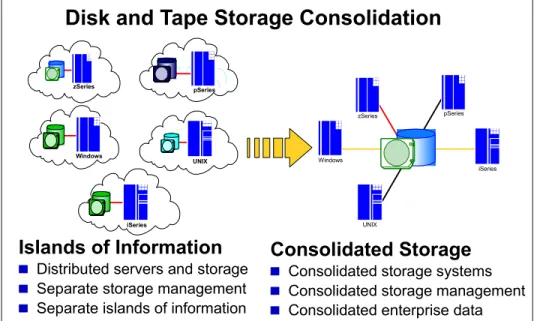
Figure 2-2 illustrates the consolidation movement from the distributed islands of information toward a single, and, most importantly, simplified infrastructure.
Figure 2-2 Disk and tape storage consolidation
Simplified storage environments have fewer elements to manage, which leads to increased resource utilization, simplifies storage management, and can provide economies of scale for owning disk storage servers. These environments can be more resilient and provide an infrastructure for virtualization and automation.
2.2.2 Information lifecycle management
Information has become an increasingly valuable asset, but as the amount of information grows, it becomes increasingly costly and complex to store and manage it. Information lifecycle management (ILM) is a process for managing information through its life cycle, from conception until intentional disposal, in a manner that optimizes storage, and maintains a high level of access at the lowest cost.
A SAN implementation makes it easier to manage the information lifecycle as it integrates applications and data into a single-view system, in which information resides, and can be managed more efficiently.
Disk and Tape Storage Consolidation
Islands of Information
Distributed servers and storage Separate storage management Separate islands of information
Consolidated Storage
Consolidated storage systems Consolidated storage management Consolidated enterprise data
zSeries pSeries Windows UNIX iSeries zSeries Windows UNIX pSeries iSeries
Chapter 2. How, and why, can we use a SAN? 15
2.2.3 Business continuity
It goes without saying that the business climate in today's on demand era is highly competitive. Customers, employees, suppliers, and business partners expect to be able to tap into their information at any hour of the day from any corner of the globe. Continuous business operations are no longer
optional—they are a business imperative to becoming successful, and maintaining a competitive advantage. Businesses must also be increasingly sensitive to issues of customer privacy and data security, so that vital information assets are not compromised. Factor in those legal and regulatory requirements, and the inherent demands of participating in the global economy, and
accountability, and all of a sudden the lot of an IT manager is not a happy one. It is little wonder that a sound and comprehensive business continuity strategy has become a business imperative, and SANs play a key role in this. By
deploying a consistent and safe infrastructure, they make it possible to meet any availability requirements.
2.3 Using the SAN components
The foundation that a SAN is built on is the interconnection of storage devices and servers. This section further discusses storage, interconnection
components, and servers, and how different types of servers and storage are used in a typical SAN environment.
2.3.1 Storage
This section briefly describes the main types of storage devices that can be found in the market.
Disk systems
In brief a disk system is a device in which a number of physical storage disks sit side-by-side. By being contained within a single “box”, a disk system usually has a central control unit that manages all the I/O, simplifying the integration of the system with other devices, such as other disk systems or servers.
Depending on the “intelligence” with which this central control unit is able to manage the individual disks, a disk system can be a JBOD or a RAID. Just A Bunch Of Disks (JBOD)
In this case, the disk system appears as a set of individual storage devices to the device they are attached to. The central control unit provides only basic functionality for writing and reading data from the disks.
Redundant Array of Independent Disks (RAID)
In this case, the central control unit provides additional functionality that makes it possible to utilize the individual disks in such a way to achieve higher fault-tolerance and/or performance. The disks themselves appear as a single storage unit to the devices to which they are connected.
Depending on the specific functionality offered by a particular disk system, it is possible to make it behave as a RAID and/or a JBOD; the decision as to which type of disk system is more suitable for a SAN implementation strongly depends on the performance and availability requirements for this particular SAN.
Tape systems
Tape systems, in much the same way as disk systems do, are devices that comprise all the necessary apparatus to manage the use of tapes for storage purposes. In this case, however, the serial nature of a tape makes it impossible for them to be treated in parallel, as RAID devices are leading to a somewhat simpler architecture to manage and use.
There are basically three types of systems: drives, autoloaders and libraries, that are described as follows.
Tape drives
As with disk drives, tape drives are the means by which tapes can be connected to other devices; they provide the physical and logical structure for reading from, and writing to tapes.
Tape autoloaders
Tape autoloaders are autonomous tape drives capable of managing tapes and performing automatic back-up operations. They are usually connected to high-throughput devices that require constant data back-up.
Tape libraries
Tape libraries are devices capable of managing multiple tapes simultaneously and, as such, can be viewed as a set of independent tape drives or autoloaders. They are usually deployed in systems that require massive storage capacity, or that need some kind of data separation that would result in multiple single-tape systems. As a tape is not a random-access media, tape libraries cannot provide parallel access to multiple tapes as a way to improve performance, but they can provide redundancy as a way to improve data availability and fault-tolerance. Once more, the circumstances under which each of these systems, or even a disk system, should be used, strongly depend on the specific requirements that a
Chapter 2. How, and why, can we use a SAN? 17 particular SAN implementation has. However, we can say that disk systems are usually used for online storage due to their superior performance, whereas tape systems are ideal for offline, high-throughput storage, due to the lower cost of storage per byte.
In the next section we describe the prevalent connectivity interfaces, protocols and services for building a SAN.
2.3.2 SAN connectivity
SAN connectivity comprises all sorts of hardware and software components that make possible the interconnection of storage devices and servers. In this section, we have divided these components into three sections according to the level abstraction to which they belong: lower level layers, middle level layers, and higher level layers.
Lower level layers
This section comprises the physical data-link, and the network layers of connectivity.
Ethernet interface
Ethernet adapters are typically used on conventional server-to-server or workstation-to-server network connections. They build up a common-bus topology by which every attached device can communicate with each other, using this common-bus for such. An Ethernet adapter can reach up to 10 Gbps of data transferred.
Fibre Channel
Fibre Channel (FC) is a serial interface (usually implemented with fiber-optic cable, and is the primary architecture for the vast majority of SANs. To support this there are many vendors in the marketplace producing Fibre Channel adapters, and other FC devices. One of the reasons that FC is so popular is that it allows the maximum SCSI cable length of 25 meters restriction to be overcome. Coupled with the increased speed that it supports, it quickly became the
connection of choice.
Note: With respect to data throughput speeds, in this redbook we use the following representations: 1 Gbps = 100 MBps 2 Gbps = 200 MBps 4 Gbps = 400 MBps 8 Gbps = 800 MBps 10 Gbps = 1000 MBps
SCSI
The Small Computer System Interface (SCSI) is a parallel interface. SCSI devices are connected to form a terminated bus (the bus is terminated using a terminator). The maximum cable length is 25 meters, and a maximum of 16 devices can be connected to a single SCSI bus. The SCSI interface has many configuration options for error handling and supports both disconnect and reconnect to devices and multiple initiator requests. Usually, a host computer is an initiator. Multiple initiator support allows multiple hosts to attach to the same devices and is used in support of clustered configurations. The Ultra3 SCSI adapter today can have a data transfer up to 160 MBps.
Middle level layers
This section comprises the transport protocol and session layers.
FCP
The Fibre Channel Protocol (FCP) is the interface protocol of SCSI on Fibre Channel. It is a gigabit speed network technology primarily used for Storage Networking. Fibre Channel is standardized in the T11 Technical Committee of the InterNational Committee for Information Technology Standards (INCITS), an American National Standard Institute (ANSI) accredited standards committee. It started for use primarily in the supercomputer field, but has become the standard connection type for storage area networks in enterprise storage. Despite its name, Fibre Channel signaling can run on both twisted-pair copper wire and fiber optic cables.
iSCSI
Internet SCSI (iSCSI) is a transport protocol that carries SCSI commands from an initiator to a target. It is a data storage networking protocol that transports standard Small Computer System Interface (SCSI) requests over the standard Transmission Control Protocol/Internet Protocol (TCP/IP) networking technology. iSCSI enables the implementation of IP-based storage area networks (SANs), enabling customers to use the same networking technologies — for both storage and data networks. As it uses TCP/IP, iSCSI is also well suited to run over almost any physical network. By eliminating the need for a second network technology just for storage, iSCSI has the potential to lower the costs of deploying networked storage.
FCIP
Fibre Channel over IP (FCIP) is also known as Fibre Channel tunneling or storage tunneling. It is a method to allow the transmission of Fibre Channel information to be tunnelled through the IP network. Because most organizations already have an existing IP infrastructure, the attraction of being able to link geographically dispersed SANs, at a relatively low cost, is enormous.
Chapter 2. How, and why, can we use a SAN? 19 FCIP encapsulates Fibre Channel block data and subsequently transports it over a TCP socket. TCP/IP services are utilized to establish connectivity between remote SANs. Any congestion control and management, as well as data error and data loss recovery, is handled by TCP/IP services, and does not affect FC fabric services.
The major point with FCIP is that is does not replace FC with IP, it simply allows deployments of FC fabrics using IP tunnelling. The assumption that this might lead to is that the “industry” has decided that FC-based SANs are more than appropriate, and that the only need for the IP connection is to facilitate any distance requirement that is beyond the current scope of an FCP SAN.
iFCP
Internet Fibre Channel Protocol (iFCP) is a mechanism for transmitting data to and from Fibre Channel storage devices in a SAN, or on the Internet using TCP/IP.
iFCP gives the ability to incorporate already existing SCSI and Fibre Channel networks into the Internet. iFCP is able to be used in tandem with existing Fibre Channel protocols, such as FCIP, or it can replace them. Whereas FCIP is a tunneled solution, iFCP is an FCP routed solution.
The appeal of iFCP is that for customers that have a wide range of FC devices, and who want to be able to connect these using the IP network, iFCP gives the ability to permit this. iFCP can interconnect FC SANs with IP networks, and also allows customers to use the TCP/IP network in place of the SAN.
iFCP is a gateway-to-gateway protocol, and does not simply encapsulate FC block data. Gateway devices are used as the medium between the FC initiators and targets. As these gateways can either replace or be used in tandem with existing FC fabrics, iFCP could be used to help migration from a Fibre Channel SAN to an IP SAN, or allow a combination of both.
FICON
FICON architecture is an enhancement of, rather than a replacement for, the now relatively old ESCON® architecture. As a SAN is Fibre Channel based, FICON is a prerequisite for z/OS systems to fully participate in a heterogeneous SAN, where the SAN switch devices allow the mixture of open systems and mainframe traffic.
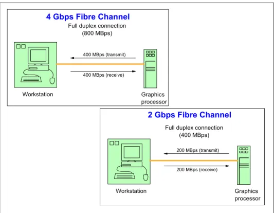
FICON is a protocol that uses Fibre Channel as its physical medium. FICON channels are capable of data rates up to 200 MBps full duplex, they extend the channel distance (up to 100 km), increase the number of control unit images per link, increase the number of device addresses per control unit link, and retain the topology and switch management characteristics of ESCON.
Higher level layers
This section comprises of the presentation and application layers.
Server-attached storage
The earliest approach was to tightly couple the storage device with the server. This server-attached storage approach keeps performance overhead to a minimum. Storage is attached directly to the server bus using an adapter card, and the storage device is dedicated to a single server. The server itself controls the I/O to the device, issues the low-level device commands, and monitors device responses.
Initially, disk and tape storage devices had no on-board intelligence. They just executed the server’s I/O requests. Subsequent evolution led to the introduction of control units. Control units are storage off-load servers that contain a limited level of intelligence, and are able to perform functions, such as I/O request caching for performance improvements, or dual copy of data (RAID 1) for availability. Many advanced storage functions have been developed and implemented inside the control unit.
Network Attached Storage
Network Attached Storage (NAS) is basically a LAN-attached file server that serves files using a network protocol such as Network File System (NFS). NAS is a term used to refer to storage elements that connect to a network and provide file access services to computer systems. A NAS storage element consists of an engine that implements the file services (using access protocols such as NFS or CIFS), and one or more devices, on which data is stored. NAS elements may be attached to any type of network. From a SAN perspective, a SAN-attached NAS engine is treated just like any other server, but a NAS does not provide any of the activities that a server in a server-centric system typically provides, such as e-mail, authentication, or file management.
NAS allows more hard disk storage space to be added to a network that already utilizes servers without shutting them down for maintenance and upgrades. With a NAS device, storage is not an integral part of the server. Instead, in this storage-centric design, the server still handles all of the processing of data, but a NAS device delivers the data to the user. A NAS device does not need to be located within the server but can exist anywhere in the LAN and can be made up of multiple networked NAS devices. These units communicate to a host using Ethernet and file-based protocols. This is in contrast to the disk units discussed earlier, which use Fibre Channel protocol and block-based protocols to
communicate.
NAS storage provides acceptable performance and security, and it is often less expensive for servers to implement (for example, ethernet adapters are less expensive than Fibre Channel adapters).
Chapter 2. How, and why, can we use a SAN? 21 In an effort to bridge the two worlds and to open up new configuration options for customers, some vendors, including IBM, sell NAS units that act as a gateway between IP-based users and SAN-attached storage. This allows for the connection of the storage device of choice (an ESS, for example) and share it between your high-performance database servers (attached directly through Fibre Channel) and your end users (attached through IP) who do not have performance requirements nearly as strict.
NAS is an ideal solution for serving files stored on the SAN to end users in cases where it would be impractical and expensive to equip end users with Fibre Channel adapters. NAS allows those users to access your storage through the IP-based network that they already have.
2.3.3 Servers
Each of the different server platforms (IBMEserver zSeries®, UNIX, AIX®, HP, Sun, Linux, and others), OS/400®, and Windows (PC Servers) have
implemented SAN solutions using various interconnects and storage technologies. The following sections review these solutions and the different implementations on each of the platforms.
Mainframe servers
In simple terms, a mainframe is a single, monolithic and possibly multi-processor high-performance computer system. Apart from the fact that IT evolution has been pointing toward a more distributed and loosely coupled infrastructure, mainframes still play an important role on businesses that depend on massive storage capabilities.
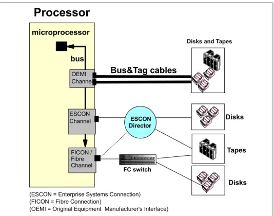
The IBMEserver zSeries (formerly known as S/390®) is a processor(s) and operating system mainframe set. Historically, zSeries servers have supported many different operating systems, such as z/OS, OS/390®, VM, VSE, and TPF, which have been enhanced over the years. The processor to storage device interconnection has also evolved from a bus and tag interface to ESCON channels, and now to FICON channels. Figure 2-3 on page 22 shows the various processor-to-storage interfaces.
Figure 2-3 Processor-to-storage interface connections
Due to architectural differences, and extremely strict data integrity and
management requirements, the implementation of FICON has been somewhat behind that of FCP on open systems. However, at the time of writing, FICON has now caught up with FCP SANs, and they coexist quite amicably.
For the latest news on zSeries TotalStorage products, refer to:
http://www-1.ibm.com/servers/storage/product/products_zseries.html
For the latest news on zSeries FICON connectivity, refer to:
http://www-1.ibm.com/servers/eserver/zseries/connectivity/
In addition to FICON for traditional zSeries operating systems, IBM has standard Fibre Channel adapters for use with zSeries servers that can implement Linux®.
UNIX-based servers
Originally designed for high-performance computer systems, such as
mainframes, the UNIX operating systems is today present on a great variety of hardware platforms, ranging from Linux-based PCs to dedicated large-scale
Tapes microprocessor bus OEMI Channel ESCON Channel
Bus&Tag cables
Processor
(ESCON = Enterprise Systems Connection) (FICON = Fibre Connection)
(OEMI = Original Equipment Manufacturer's Interface) FICON /
Fibre Channel
Disks and Tapes
Disks
Disks FC switch
ESCON Director