DESIGNER POLARIZATION
(for magazine publication)INTRODUCTION
Historically, Radar Warning Receivers (RWR) employ cavity backed spiral antennas to detect and classify threats to the aircraft and to determine their direction of arrival. These spiral
antennas are circularly polarized and can sense signals of all polarizations with varying sensitivity except the opposite sensed circular polarization.
In 1983, Randtron Antenna Systems developed a common aperture antenna with performance equal to or better than a spiral antenna of the same size and capable of simultaneously receiving both senses of circular polarization. This antenna is the Dual Polarized Sinuous Antenna (DPSA). The DPSA has two output ports that provide maximum response to left- and right-hand circularly polarized incoming signals and also respond well to any linear polarization. As a result, one port or the other will always receive any polarized signal with sensitivity that is no less that 3 dB below the matched polarization sensitivity.
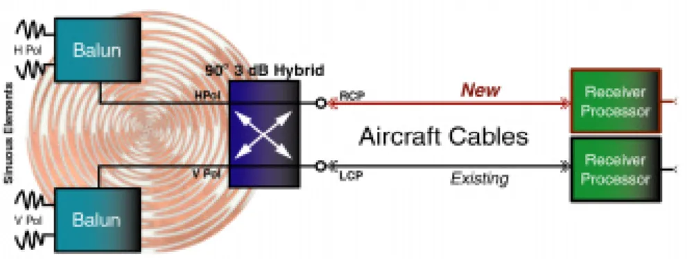
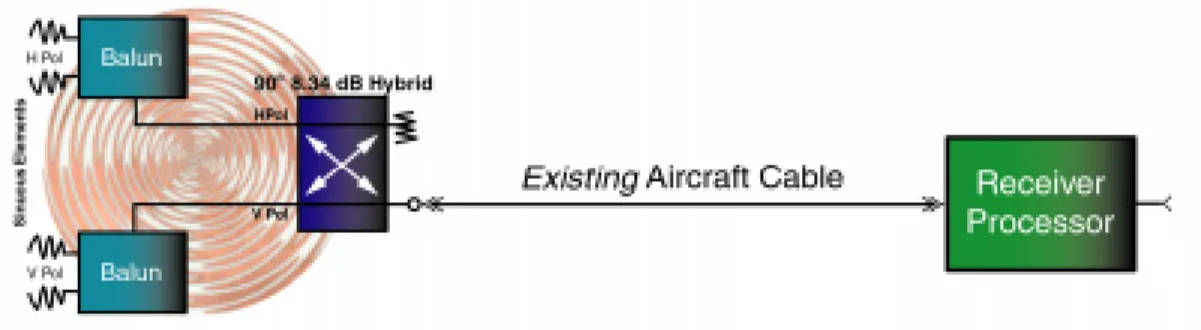
Figure 1 depicts the block diagram of the sinuous antenna, which includes the Horizontal and Vertical Polarization elements, the Baluns and the 90° Hybrid Coupler. In order to upgrade an existing RWR system for monopulse all polarization capability using the two-port DPSA, an additional cable and receiver channel is required. Figure 1 shows how this is accomplished. The added hardware is shown in red.
Figure 1 - Implementation of Two-Port Sinuous Antenna in RWR system
To reduce the cost, the second Receiver/Processor in Figure 1 can be eliminated if a RF Switch is added to time-share the two outputs of the DPSA. However this also requires modifying the Receiver/Processor to add the hardware and software to control the RF Switch.
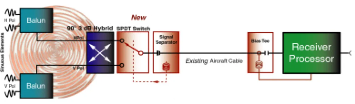
For further system cost reduction, the DPSA was revised to provide an optional internal RF switch eliminating the need for the additional cable. Figure 2 shows how this is accomplished. As shown in the illustration, the cable is used to carry the signal controlling the RF Switch as well as the received signal itself. The control signal is injected and extracted by bias isolation
Figure 2 - Implementation of Dual Polarization with Integrated RF Switch
Both of the above implementations are capable of sensing all polarizations. An alternative solution has been developed that makes use of the unique polarization diversity properties of the sinuous antenna and eliminates the modifications to the remainder of the RWR entirely. The idea is to provide a tailored polarization that receives all major polarizations (V, H, LCP, RCP, Slant) with good antenna patterns and only shows poor polarization response to some obscure
polarization. This tailored polarization would be based on the relative strengths and likelihood of the signals expected in common mission RF environments. A study of polarization theory reveals how the dual polarization capability of the sinuous antenna can be exploited to create a targeted, designer polarization.
This article illustrates how the DPSA can be used to respond optimally to any specific
polarization by creating a designer polarization. Before we delve into the designer polarization technique, it is important to briefly review the operation of the sinuous antenna. Following that, is a discussion of how to create an antenna having a specific polarization. Finally, this article concludes with an example of hardware designed and tested at Randtron Antenna Systems that implements a designer polarization. This implementation responds to the normal left and right circular polarizations and to horizontal and vertical linear polarizations.
SINUOUS ANTENNA THEORY OF OPERATION
The DPSA was originally designed to meet the challenge in Radar Warning Systems posed by hostile signals that can be linear, right-hand or left-hand circular polarization. In recent times, this antenna has also found applications in ESM, EW and SIGINT systems, as a sensor for
polarimeter systems and as a feed for reflectors in antenna test ranges.
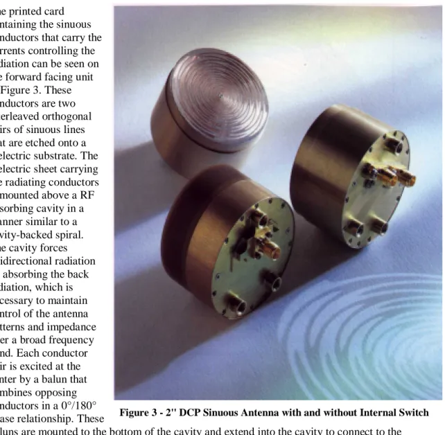
A comprehensive technical discussion of the sinuous antenna can be found in the patent of Dr. R. H. DuHamel. Randtron Antenna Systems has exclusive rights to this patent. DuHamel and Scherer have published the detailed theory of operation of the DPSA1. The DPSAs uniform radiation characteristics are obtained from its radiating aperture. A photograph of several operational DPSAs is shown in Figure 3.
The printed card containing the sinuous conductors that carry the currents controlling the radiation can be seen on the forward facing unit in Figure 3. These conductors are two interleaved orthogonal pairs of sinuous lines that are etched onto a dielectric substrate. The dielectric sheet carrying the radiating conductors is mounted above a RF absorbing cavity in a manner similar to a cavity-backed spiral. The cavity forces unidirectional radiation by absorbing the back radiation, which is necessary to maintain control of the antenna patterns and impedance over a broad frequency band. Each conductor pair is excited at the center by a balun that combines opposing conductors in a 0°/180° phase relationship. These
baluns are mounted to the bottom of the cavity and extend into the cavity to connect to the conductors of the etched board.
The DPSA has been designed to produce either its latent dual-linear polarization (DLP) or, more commonly, in conjunction with a quadrature hybrid, dual-circular polarization (DCP). This quadrature coupler is a very wideband Randtron Antenna Systems designed stripline 3 dB quadrature hybrid coupler which is specially packaged for DPSA integration. The signals received at each of the dual balun outputs are combined in a ±90° phase relationship by the four port hybrid. The two output ports thus provide right-hand circular polarization (RHCP) and left-hand circular polarization (LHCP) simultaneously. As mentioned above, the DPSA is available in options with outputs in individual ports for simultaneous dual polarization or switch selected.
DESIGNER POLARIZATION THEORY
The sinuous antenna is fundamentally a dual orthogonal linear polarized radiator with an output connector for each linear polarization. It is well known that by combining the signals from these two outputs with varying amplitude and phase ratios, any polarization can be created. Thus the DPSA has the capability of creating a specific Designer Polarization.
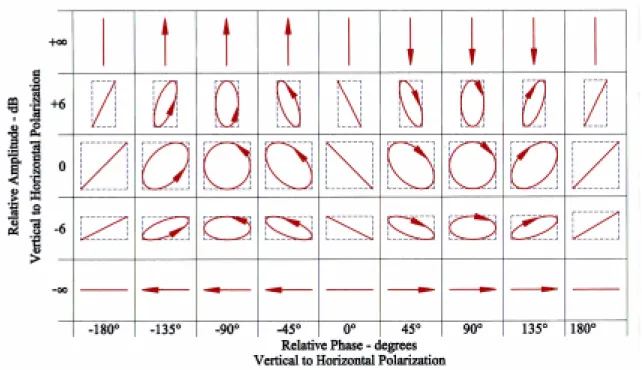
All polarizations fall into the general category of elliptical polarization, the general case of which linear and circular polarizations are limiting cases. Figure 4 below shows the relationship between the amplitude and phase of the power fed to the two sinuous inputs and the polarization of the approaching wave. The mathematics of the polarization shown in Figure 4 is included in the Appendix at the end of this document. For the cases of ±∞ dB, we have the limiting case of linear vertical and horizontal polarizations. For the case of 0 dB and ±90°, we have left and right hand circular polarizations. Slant polarizations result for the in and out of phase conditions of 0° and 180°.
DESIGNER POLARIZATION EXAMPLE
Designer Polarization has been validated in hardware using an easy-to-implement special case. This special case was designed to produce a predominately Left Slant Left Hand Elliptical Polarization with a Left Slant to Right Slant Linear polarization ratio of 8.34 dB. With this polarization, the theoretical response relative to the design polarization is shown in the following table.
Table 1 - Polarization Response of Designer Polarization to Standard Incident Polarizations
Polarization RHCP LHCP Horizontal Vertical Slant Left Slant Right
Response - dB -7.8 -0.8 -3.0 -3.0 -0.6 -8.9
This was easy to implement because our Dual CP Sinuous antenna contains a tandem quadrature hybrid to generate Circular Polarization with the linear antenna elements. A tandem quadrature hybrid consists of two 8.34 dB hybrids tied together to form a 3 dB hybrid. By bypassing one of these hybrids, the desired 8 dB Elliptical Polarization is readily achieved. Figure 5 depicts the system using this implementation. Note that no modifications are required to existing systems other than the antenna replacement.
Figure 5 - Implementation of Designer Polarization
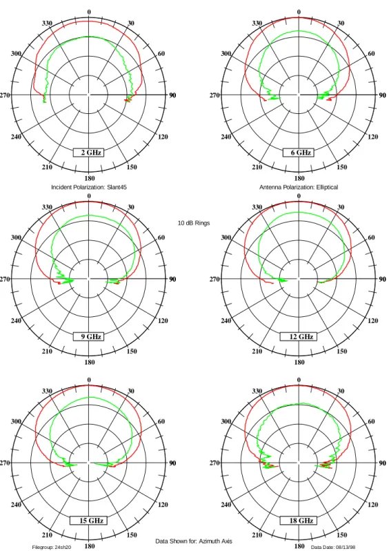
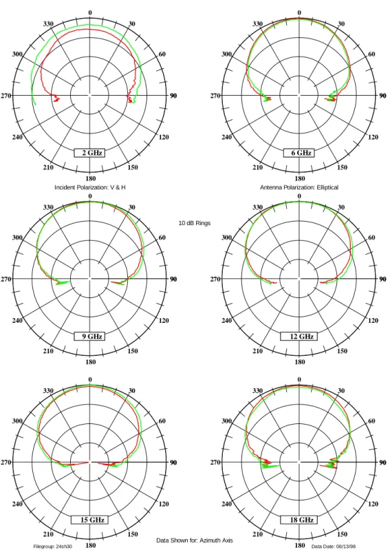
Test results for the 8 dB Left Slant Elliptical Polarization antenna follow in the form of antenna patterns at sampled frequencies in the 2 to 18 GHz band. Figure 6 shows the patterns taken with Left and Right Linear Slant Polarizations and Figure 7 shows the patterns with Horizontal and Vertical Polarizations. Note the approximate 8 - 9 dB difference for the slant polarization of Figure 6 and approximate equal response for horizontal and vertical polarizations of Figure 7.
The beauty of this design is that this antenna will have reasonable gain and well-behaved patterns to the four major polarizations (right and left circular, vertical and horizontal linear) from a single port. Furthermore, no system hardware changes are required to implement the increased polarization capability. By contrast, a spiral responds to its opposite sense circular
polarization with unpredictable gain and pattern characteristics rendering the information
unusable in a typical DF or EW system. The sinuous is the only common aperture dual polarized solution currently available in which the relationship between these polarizations is maintained over the broad angular range of the antenna beam and the broad frequency range.
Any system using broadband spiral elements such as quadrant DF, Interferometers, Jammer repeaters, etc., are candidates for these sinuous elements. Overall system performance will be maintained and blindness to one sense of threat polarization is eliminated simply by a direct replacement with no added hardware and little, if any, software changes.
CONCLUSION
A technique for generation of an arbitrary antenna polarization has been analyzed and
successfully tested. Designer Polarization can be used to simplify airborne RWR, ESM and EW systems when upgrading to increased polarization diversity.
The key to the success of Designer Polarization is the use of the Sinuous Antenna. The Sinuous Antenna has the unique feature of generating or receiving simultaneous all polarizations from a common spiral-like aperture. Furthermore, the antenna, like no other, can maintain this capability over a very wide frequency band and very wide field of view. The importance of this common aperture with coincident phase centers to the success of designer polarization cannot be overstressed; a pair of antennas that do not collect signals at the same physical location as the sinuous does, will produce a variation in phase that degrades the polarization purity over space.
90 120 150 180 210 240 270 300 330 0 30 60 90 2 GHz 2 GHz 90 120 150 180 210 240 270 300 330 0 30 60 90 6 GHz 6 GHz 90 120 150 180 210 240 270 300 330 0 30 60 90 9 GHz 9 GHz 90 120 150 180 210 240 270 300 330 0 30 60 90 12 GHz 12 GHz 90 120 150 180 210 240 270 300 330 0 30 60 90 15 GHz 15 GHz 90 120 150 180 210 240 270 300 330 0 30 60 90 18 GHz 18 GHz
Filegroup: 24sh20 Data Date: 08/13/98
Data Shown for: Azimuth Axis
Incident Polarization: Slant45 Antenna Polarization: Elliptical
10 dB Rings
Figure 6 – Left & Right Slant Linear Polarization Radiation Patterns of 8dB Left Slant Elliptically Polarized Antenna
90 120 150 180 210 240 270 300 330 0 30 60 90 2 GHz 2 GHz 90 120 150 180 210 240 270 300 330 0 30 60 90 6 GHz 6 GHz 90 120 150 180 210 240 270 300 330 0 30 60 90 9 GHz 9 GHz 90 120 150 180 210 240 270 300 330 0 30 60 90 12 GHz 12 GHz 90 120 150 180 210 240 270 300 330 0 30 60 90 15 GHz 15 GHz 90 120 150 180 210 240 270 300 330 0 30 60 90 18 GHz 18 GHz
Filegroup: 24sh30 Data Date: 08/13/98
Data Shown for: Azimuth Axis
Incident Polarization: V & H Antenna Polarization: Elliptical
10 dB Rings
Appendix - Polarization Synthesis Summary
Any polarization can be synthesized by controlling the relative amplitude and phase of two coherent signals input to two antennas that are orthogonal polarized. Furthermore, if the responses of the two antennas are identical in all directions in space the polarization generated by the two antennas will be maintained in all directions in space. It is common to consider the general polarization to be composed of vertical and horizontal polarization components. The equation of the electric field generated by the horizontal and vertical electric field component magnitudes EH
and EV respectively and relative phase φ is:
)
cos(
)
cos(
ω
+
ω
+
φ
=
i
E
Ht
j
E
Vt
E
.Since the polarization of the electric field is the item of interest, the equation can be simplified without the time varying terms of ω t as:
y
x
j
i
E
=
+
.The x and y terms are the respective magnitudes of the polarization vector for the horizontal and vertical antenna coordinate system. This equation can be manipulated in the form of an ellipse, the general case describing the direction of the polarization vector, as follows:
0
sin
cos
2
2 2 2 2 2=
−
+
−
φ
φ
V V H HE
y
E
E
xy
E
x
.The above defines the general equation an ellipse centered in the plane of the antennas horizontal and vertical radiators, x and y respectively. The equation can also be more conveniently written in terms of the ratio of EV to
EH. The major axis of the ellipse is inclined to the x axis by the angle ψ, which is:
2 2
cos
2
2
tan
V H V HE
E
E
E
−
=
φ
ψ
.The polarizations of greatest interest occur for φ = 0°, 90°, 180° & 270° as follows.
Linear Polarizations
A line through the origin with slope m defines linear polarizations. In phase case (φ = 0°): H V V H
E
E
m
E
y
E
x
=
=
−
0
,
.Out of phase case (φ = 180°):
H V V H
E
E
m
E
y
E
x
−
=
=
+
0
,
. Elliptical PolarizationsWhen φ = 90° or 270°, the polarization vector rotates at the RF frequency. The direction of rotation is Left for φ = 90° and Right for φ = 270°. The equation for the ellipse traced out by the tip of the rotating polarization is:
1
2 2 2 2=
+
V HE
y
E
x
.When EH = EV then the polarizations are LHCP (Left Hand
Circular Polarization) and RHCP. In general, the
polarization will be predominately LHCP for 0° < φ <180° and will be predominately RHCP for 180° < φ < 360°.