P-CIM
Contents
About this Manual ...11
License and Registration ... 12
P-CIM I/O Counters ... 12
Support ... 12
Ordering New Software... 12
Introduction... 14
About P-CIM ... 15
Minimum System Requirements ...16
Installing P-CIM ...17
Downloading P-CIM from the Internet ... 17
Uninstalling P-CIM... 18
P-CIM Interface ... 19
P-CIM icons groups ...20
Creating the P-CIM Group shortcu... t 20
P-CIM Group Modules ... 21
P-CIM Architecture ...26
Project Architecture ... 27
Communications Layer ...28
Database Layer... 29
Application Layer ...30
Project Management... 32
Working with Projects ...36
Default Projects... 36
Deleting Projects ...37
Backing Up Projects ...37
Project Setup Settings ... 37
Restoring Projects... 40
Designing the Yogurt Project ... 43
Yogurt Production Workflow...44
Requirements for Building an Automation System ... 44
Communication Layer ...46
About the Communications Layer ...47
P-CIM Drivers ...47
Defining Driver Parameters...49
P-CIM Communication Setup ...49
New Ports ... 49
Fine Tuning Parameters ...50
Defining Polling Configurations... 53
P-CIM Syntax for Driver Addresses ... 55
Checking Communications ...56
Data Scope 56
Working in the Data Scope... 56
Alarm Summary - System Messages ... 58
Communications Layer Troubleshooting ... 60
Error Messages Indicating Problems during Initialization of the Driver... 60
Error Messages Indicating Writing to an Undefined Memory Range in the PLC 61
Error Message Indicating Communication Failure ... 61
Defining Data Items ...63
Syntax Legend ...70
To View the Aliases List in the Syntax Manager ...70
Animation Editor ...71
Toolbox ...72
Selected Object Signs ...73
Creating a New Display ... 74
Drawing a Graphical Object ...76
Basic Information... 76
Adding Properties to Graphical Objects ...85
Property References ...85
The Visibility Property ... 86
The Fill Color Property... 89
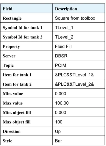
The Fluid Fill Property ... 91
The Orientation Property ... 94
The Output Text Property ...96
The Input Text Property ...99
The Slider Property ... 102
The Action Button Property ... 105
Basic Information... 105
Basic P-CIM Action Commands 1 ...05
Cells ... 112
Basic Information for Designing Cells ... 113
$Variables ... 114
Dummy Variables ... 117
Dummy Variable Syntax ... 117
DBSR Functions ... 118
DBSR Conversions ... 121
Conversion LIN (Linear) ... 122
AutoActions ... 125
Creating Startup and Shutdown Actions ... 125
Running the Operator Workstation during P-CIM Startup... 126
Defining AutoOpen/AutoClose Actions... 127
Defining AutoActions ... 127
Database Editor... 132
About the Database Editor ... 133
Configuring the Database ... 133
Data Blocks ... 134
Types of Database Blocks ... 135
OLEDB Database ... 139
Alarms ... 140
Configuring Alarms ... 141
Defining an Analog Alarm ... 141
Defining an Alarm in an Alarm Block ... 143
Displaying Alarms ... 146
Alarms Status ... 147
Advanced Alarm Handler ... 149
About the Advanced Alarm Handler ... 150
Building an Advanced Alarms System ... 150
Planning Alarm Categories ... 150
Planning Advanced Alarm Handler Zones ... 151
Defining Data Blocks Advanced Parameters ... 154
Configuring Alarms 1 ...54
Viewing Alarms ... 156
Working in the Advanced Alarm Handler Window ... 156
View Menu ... 156
Filtering Views ... 157
Customizing the List ... 159
Sorting Alarms... 159
Customizing the Toolbar... 160
Setting Alarm Message Colors ... 161
Archiving ... 162
Handling Alarms ... 162
Acknowledging alarms ... 162
Erasing Alarms ... 163
Purging Alarms ... 163
Trends ... 165
Real-time Trends ... 166
Displaying a Real-time Trend ... 169
Historical Trends... 170
History Collection ... 170
Displaying a Historical Trend... 173
Dynamic Trends ... 174
DOT Fields ... 180
About Dot Fields ... 181
.ACK ... 181
.ALMHigh ... 182
.ALMLow ... 183
.ALMEnable ... 183
Dynamic Display ... 186
About Dynamic Displays ... 187
Creating the Main Display ... 190
Recipes ... 192
About Recipes ... 193
Defining Recipes ... 193
Using Recipes during Runtime 1 ...95
Loading Recipes ... 195
Learning Recipes ... 195
Reports ... 199
About Reports ... 200
Defining and Formatting Report Templates ... 200
Defining a TXT Report... 201
Running and Viewing Reports ... 203
Defining a DBF Report ... 206
Defining the Supreme Report ... 208
Text File Server ... 213
About the Text File Server ... 214
Defining the DDE Address to the Text File ... 214
Reading INI File Data ... 215
Defining the DDE Link to the INI File ... 216
Security ... 219
Security Privileges ... 220
Defining Users and Passwords ... 220
Logging In During Runtime ... 221
Logging Out During Runtime... 223
Security for Operator Workstation Menu Commands ... 224
Security for Opening a Display ... 225
Displaying Windows Keyboard Combination Commands ... 229
Displaying Secure Windows ... 229
Password Editor ... 230
Modules Security ... 233
File Security... 234
Audit Trail ... 236
Toolbar ... 239
About the Toolbar Editor ... 240
Appendix 1 Shortcuts, Tips & Recommendations ... 244
Shortcut Keys ... 244
Tips ... 246
Recommendations ... 249
Appendix... 2
Glossary ... 250
Copyright
The information in this document is subject to change without notice and does not represent a commitment by Afcon Software and Electronics Ltd.
No part of this document may be used or reproduced in any manner whatever without written permission from Afcon Software and Electronics Ltd.
The software described in this document is provided under a license agreement or a nondisclosure agreement. The software may be used or copied only under the terms of the agreement.
It is against the law to copy this software on any other medium for any purpose other than the buyer's personal use.
© Copyright 1987 Afcon Software and Electronics Ltd.
All rights reserved.
P-CIM and P-CIM logos are registered trademarks of Afcon Software and Electronics Ltd.. Afcon and the Afcon logos are registered trademarks ofAfcon Software and Electronics Ltd. Windows is a trademark of Microsoft Corporation.
About this Manual
This manual should provide you with the information needed to build your first project. Before using P-CIM software, you should be familiar with XP and Windows 2000 operating systems or Windows 2003 Server. You should also know how to run an IBM or compatible PC.
During this course we refer to the Yogurt Project, which AFCON built for a large milk product manufacturers.
We suggest that as you go through the manual and learn about the various modules, you consult Appendix 1, Shortcuts, Tips and Recommendations. For more information about the P-CIM Supreme Report, refer to the Supreme Report User Guide, located in the documentation scetion on the Afcon CD.
• Manual Symbols
The following icons are used in this manual:
During the course the following terms are used when working with the mouse:
In P-CIM the following terms refer the P-CIM key: • Plug
• SEK • Key
This sign is for notes
This sign is for exercises
This sign is for tips
This sign is for rules
Term Description
Drag Moving a selected object while continuously pressing the left mouse button.
(Left) click Clicking on the left mouse button.
Right click Clicking on the right mouse button. Right clicking normally opens a dropdown menu.
License and Registration
The license and registration forms are part of P-CIM software. Please complete them and return them to us.
P-CIM I/O Counters
The number of I/O points and CIM application, either runtime or development, are defined in the P-CIM SEK.
Support
Any questions that you have during the course can be discussed with your instructor. After the course, you can e-mail your questions to the following address: [email protected]
Ordering New Software
This chapter introduces you to P-CIM. Also discussed are the requirements for running P-CIM and how to install and uninstall the program.
Chapter 1 Introduction
In this chapter you will learn ….
• About P-CIM
• About the requirements for running P-CIM • How to install P-CIM
1.1 About P-CIM
P-CIM software is used to design a customized control and automation project that runs your workplace.
In a P-CIM project, P-CIM database continually collects and data in real-time. Results of the process are analyzed, and when necessary, events and alarms are sent to the responsible personnel.
P-CIM runs on PCs, and is connected to Programmable Logic Controllers (PLC) and field devices, or to third-party databases.
During this course we will be referring to the Yogurt Project, which AFCON built for a large milk product manufacturers.
Below is an illustration of a P-CIM project.
Operator Workstations
P L A N T F L O O R
PLC ControllersRedundant Servers
Web email Cellular
P-CIM P-CIM P-CIM
1.2 Minimum System Requirements
P-CIM version 7.70 supports Windows 2000, Windows XP and Windows 2003 Server.
• Intel Pentium 4 • 256MB RAM
• 15GB free disk space for initial installation • VGA display card with 16MB of memory • Parallel printer port or USB
• Network adapter and fixed IP address for network applications
• Microsoft IIS for P-CIM Web server (for P-CIM Web and/or Supreme Report Web portal) • MIcrosoft Access or SQL server (for P-CIM database and/or Supreme Report database)
1.3 Installing P-CIM
Install P-CIM from the P-CIM from the CD or, downloaded from the Afcon web site at the following address: www.afcon-inc.com.
• Installing P-CIM from the Afcon CD
1. Insert the Afcon CD into the CD drive. Wait for it to open on your screen. 2. Click P-CIM and then click the Install P-CIM Packages option.
3. Click the latest P-CIM version, and then click P-CIM/Install P-CIM packages/P-CIM 7.70.
4. The Install Shield runs and the Welcome dialog box opens. Click Next. If you have a previous ver-sion of P-CIM installed the Choice dialog box opens.
5. In Choice dialog box select to either:
• Add the version of P-CIM to your Windows system, as well as the one that you already have. • To replace the current P-CIM version and to upgrade it.
6. Click Next to continue. The Select Destination Directory dialog box opens. The default is Pcim32. 7. Either browse and select a new directory for the program or, accept the directory that appears in the
dialog box. Click Next to run the Setup.
8. The Supreme Report installation wizard runs. Click next to start the installation process. A message informs you that the installation process was successfully completed.
9. Restart Windows before running P-CIM for the first time.
Downloading P-CIM from the Internet
1 In your Internet browser open the Afcon site at the following URL: www.afcon-inc.com. 2 From the Downloads section click P-CIM Packages and select P-CIM Version 7.70. 3 Continue installation by following the instructions on the previous page from instruction 4.
• Creating the P-CIM Group shortcut
1. Select the following: Start/Programs/AFCON P-CIM (7.70). 2. Click the AFCON P-CIM (7.70) icon and press the Ctrl button.
3. Still pressing the Ctrl button, drag the icon on to your desktop. The P-CIM Group icon opens on your desktop.
Before installing P-CIM restart your computer and make sure the program is not running.
After installing the software, connect the Software Enabled Key (SEK) to enable all the application’s features.
1.4 Uninstalling P-CIM
1. Close the application by clicking the P-CIM Shutdown icon. Log off your computer.
2. From the P-CIM icons group double click the Uninstall icon. The Uninstall dialog box opens. 3. In this dialog box select:
4. Automatic, to remove the P-CIM application from your computer without removing existing project files.
5. Custom, to remove the P-CIM application and selected projects files. 6. Click Next to open the Perform Uninstall dialog box.
7. Click Finish to continue the Uninstall process. A message box opens. 8. Click Yes, to confirm that you want to remove the application or No, not to.
Access P-CIM and its modules an Explorer like interface, created after installing P-CIM. Throughout this manual this interface is referred to as the P-CIM Group.
Chapter 2
P-CIM Interface
In this chapter you will learn ….
• To add the P-CIM Group shortcut to your desktop • About P-CIM Group icons
2.1 P-CIM icons groups
As of P-CIM version 7.50 the P-CIM icons are grouped into four groups to provide quick and easy access to P-CIM modules. The icons are placed under the following groups:
• Administrative Tools – containing administrative security utilities. These include the Modules Security, Audit Trail, Password Editor, HASP install and HASP remove.
• Development – containing modules used to develop and maintain projects. Included are: Animation Editor, Database Editor, E-mail Dispatcher, INI File Editor, Maintenance Manager, Message Setup, Network and Redundancy Editor, OPC Browser and Gateway Editor and Progate modules, Recipe Editor, Report Editor, Supreme Report Studio ,SER Editor, Syntax Manager and Toolbar Editor module.
• Runtime – contains modules accessed during P-CIM run-time. Included are: Alarm and Advanced Alarm Handler modules, Operator Workstation, OPC Gateway and Maintenance Manager, Progate Runtime, Supreme Report Runtime, P-CIM Video, Scheduler and Task Switcher modules.
• Tools – contains modules used to perform maintenance tasks. Included are: Data Scope, Database Utility, Audit Trail, Disk Space Size Predictor, E-mail Sender, FTP Utility, Global Font Replacement, Open Historian Cleanup Utility, OPC Browser Displays Conversion and History Viewer.
Access P-CIM modules from the P-CIM Group. It is more convenient to create a shortcut to the P-CIM Group on your desktop.
2.1.1 Creating the P-CIM Group shortcut
1 Select the following: Start/Programs/AFCON P-CIM (7.70). 2. Click the icon and press the Ctrl button.Still pressing the Ctrl button, drag the icon on to your desktop. The P-CIM Group icon opens on your desktop.
2.2 P-CIM Group Modules
Table 1: P-CIM Modules
P-CIM Setup Use this module to install P-CIM and its drivers and to define communication features. Use it also to create P-CIM projects, and to then backup and restore them
P-CIM Startup This module starts up P-CIM
P-CIM Shutdown This module shuts down P-CIM and its running processes
P-CIM Restart This module restarts P-CIM and its running processes
P-CIM Network Setup
Use this module to define and change network stations.
Alarm Handler This module displays system and alarm messages. It has two windows, Current Alarm and Alarm Summary.
Data Scope A diagnostic tool used to disPlay and change items and their values during runtime.
Animation Editor Use this module to create the graphic disPlays the operator sees during runtime in the Operator Workstation module.
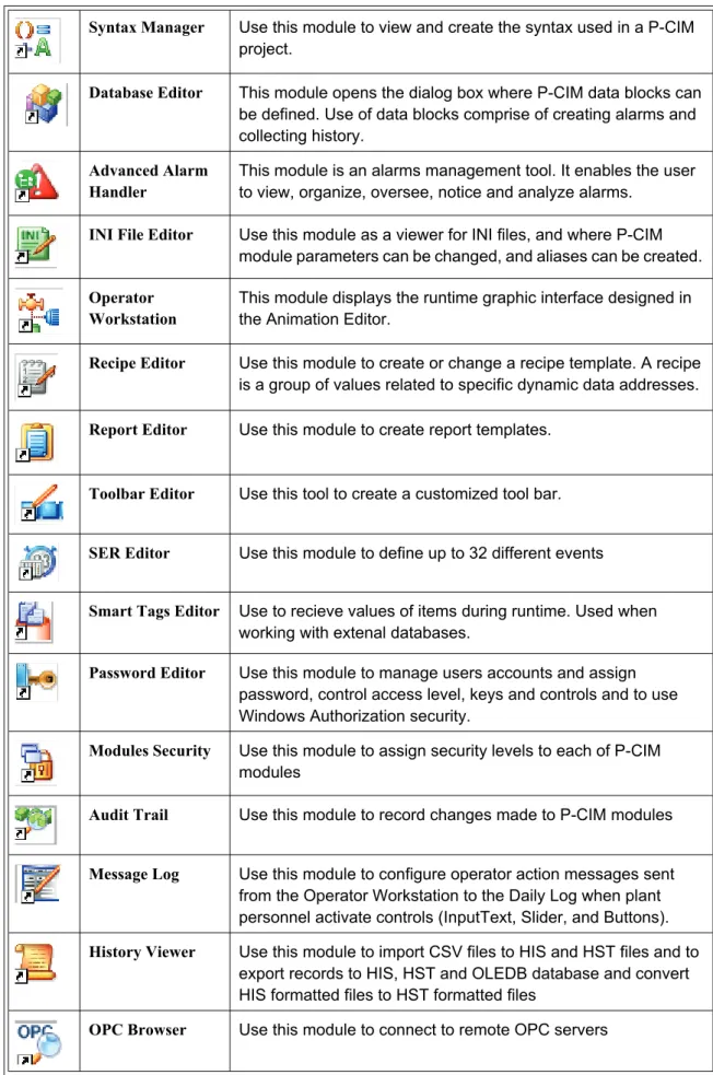
Syntax Manager Use this module to view and create the syntax used in a P-CIM project.
Database Editor This module opens the dialog box where P-CIM data blocks can be defined. Use of data blocks comprise of creating alarms and collecting history.
Advanced Alarm Handler
This module is an alarms management tool. It enables the user to view, organize, oversee, notice and analyze alarms.
INI File Editor Use this module as a viewer for INI files, and where P-CIM module parameters can be changed, and aliases can be created.
Operator Workstation
This module displays the runtime graphic interface designed in the Animation Editor.
Recipe Editor Use this module to create or change a recipe template. A recipe is a group of values related to specific dynamic data addresses.
Report Editor Use this module to create report templates.
Toolbar Editor Use this tool to create a customized tool bar.
SER Editor Use this module to define up to 32 different events
Smart Tags Editor Use to recieve values of items during runtime. Used when working with extenal databases.
Password Editor Use this module to manage users accounts and assign password, control access level, keys and controls and to use Windows Authorization security.
Modules Security Use this module to assign security levels to each of P-CIM modules
Audit Trail Use this module to record changes made to P-CIM modules
Message Log Use this module to configure operator action messages sent from the Operator Workstation to the Daily Log when plant personnel activate controls (InputText, Slider, and Buttons).
History Viewer Use this module to import CSV files to HIS and HST files and to export records to HIS, HST and OLEDB database and convert HIS formatted files to HST formatted files
OPC Browser Use this module to connect to remote OPC servers
Table 1: P-CIM Modules (Continued)
In this exercise you will open P-CIM modules and check out their menus and options.
OPC gateway Use this module to configure the OPC gateway settings
E-mail Dispatcher Use this module to configure e-mail messages' settings and schedules
Maintenance Manager
Use this module to perform maintenance related tasks
Redundancy Manager
Use this module to configure redundancy network between two or more P-CIM servers
Progate Runtime Use this module to run the Progate application
Supreme Report Studio
Use the Supreme Report Studio to design and produce PDF based reports based on records retrieved directly from the P-CIM database.
Supreme Report Runtime
Use this module to generate either schedules or on demand reports.
Uninstall P-CIM Use this module to uninstall P-CIM.
Exercise ……. Playtime!!
Table 2: P-CIM Modules Table (Sheet 1 of 2)
Icon Module Questions Answers
P-CIM Startup
What is the purpose of this module? Which five P-CIM modules are displayed in your computer’s task bar during startup?
1 Open the modules displayed in the CIM Modules table by double clicking on their icons in the P-CIM Group interface.
2 Check out their menus and options. 3 When will each module be used?
4 Write in your answers in the P-CIM Modules table Answers column.
Animation Editor
What is the purpose of this module?
Database Editor
What is the purpose of this module? How many data block types are there?
INI File Editor
What is the purpose of this module? Which file opens in the INI File Editor?
Data Scope What is the purpose of this module?
P-CIM Shutdown
During P-CIM shutdown do all open modules automatically close?
This section discusses P-CIM architecture, which is built in three layers.
Chapter 3 P-CIM Architecture
In this chapter you will learn ….
• How data arrives from the plant floor to P-CIM • How data is processed
• About the different P-CIM layers and their role in P-CIM
Project Architecture
P-CIM is built in layered format. During runtime, data in the P-CIM project is transferred through the layers bidirectionally.
Communications layer, receiving information from the workplace through the PLC and then transferring it to the database server. The following modules are used in this layer:
• P-CIM Communication Setup • Alarm Summary Windows • Data Scope
• Driver Server
Database layer, analyzing data, processing events and alarms and sending them to the user. The following modules are used in this layer:
• Database Server • Database Editor • Alarm Handler
• Advanced Alarm Handler
Application layer, displaying data and alarms to operators. The following modules are used in this layer:
• Animation Editor • Operator Workstation • Report Editor
• Recipe Editor • Basic Server • Text File Server • Toolbar Editor
Use the Project Setup dialog box to manage the P-CIM project opened from the P-CIM icons group.
Chapter 4 Project Management
In this chapter you will learn ….
* How to create a P-CIM project * About project directories * To define a default project
* To backup, delete and restore a project
P-CIM software
Sub tree for each P-CIM version installed on the operating system
Projects for each P-CIM version
Sub tree for each project containing a virtual folder for each subject, where each virtual folder when selected in the P-CIM tree, displays its description and real path on the right pane of this window
Creating Projects
The Project Setup window to manage the P-CIM project accessed by clicking the
P-CIM Setup icon in the P-CIM Group. This window displays the project tree, which contains all installed P-CIM versions and all P-CIM projects that have been created.
Each project is represented in the tree by a folder with the project’s name, under which there are subfolders that are displayed as branches containing data for different subfolders
• By default, project files are saved under the project’s folder and not under the subfolders.
• To use the subfolders, change their path location from the project’s path to another directory.
4.0.1 Workflow for Creating the Yogurt Project
Connect the P-CIM plug to the PC.
Define the project in the P-CIM Setup dialog box. Install the P-CIM driver and define driver properties.
Startup P-CIM.
Check communication between the PC and the controller.
Define Advanced Alarm Handler tree zones, alarms and history and connect them to the blocks in the database.
Define reports, recipes, security, and toolbar.
Create the graphical display, add properties to it and then open the Operator Workstation.
Define database blocks and aliases.
In this exercise you will create a new project named Yogurt.
1. In the P-CIM Group, double click the P-CIM Setup icon to open the P-CIM Setup dialog box, and then click the Project Setup button to open the Project Setup window.
2. Open the New Project dialog box by either:
• Right clicking in the tree and selecting New. • Clicking the New button on the tool bar.
-3. Complete this dialog box using the information in the New Project table.
4. Click the OK button. The name of the project and its description displayed in the window’s right pane. The window’s title bar displays the default project in use.
Exercise – creating the Yogurt project
Table 3: New Project Table
Field Text
Project name Yogurt
Project description Yogurt production
A project name must be without spaces and have no more than eight characters.
The Description of the project can be modified in the Properties dialog box.
In this exercise you will change the Yogurt project’s communication directory path.
1. Open the Properties dialog box by either:
• Expending the Projects menu, expending a project, clicking on the folders and right-clicking and selecting Properties.
• Selecting the subfolder of the project in the tree, and then clicking the Properties button in the toolbar.
• Selecting the subfolder of the project in the tree, and in the Edit menu selecting the Properties option.
2. Type in a new path (Com) and click OK to confirm. The new directory is displayed in the right pane of the Project Setup window.
4.0.1 Working with Projects
Set the project as default, back it up, restore or delete it once created.
Default Projects
In P-CIM you can create any number of projects however, the default project is always opened during P-CIM Startup.
Exercise – changing a directory path
When creating a display folder the following sub directory paths must be modified:
• PcimACT
• PcimDRW
• PcimUPD
• Defining a default project
In the Projects Tree, select a project and then either: • Right click and choose the Set as Default option. • Click the Default button on the toolbar.
• Open the File menu and select the Set as Default option.
The default project’s name is displayed in the title bar.
Deleting Projects
Projects are deleted from the system in the Project Setup window. Deleting a project removes all files from system.
• Deleting a project
1. Select the project and then either: • Right click and select Delete.
• Click the Delete button on the toolbar. • In the File menu, select the Delete option.
2. In the message box that opens, click Yes to remove the project.
Backing Up Projects
You can backup a project into several disk directories that can be restored. Backup your projects for the following reasons:
• To save a copy of the project to replace a damaged project.
• During project development, where projects are periodically saved during the different development stages.
• To transfer a project to another computer.
When backing up a project you can select to backup all the project’s directories or to backup specific directories only.
During project backup, select the backup location. The default is Pcim32.bak.
Project Setup Settings
Using the Project Setup module you can modify the settings controlling the functionality and visibility of P-CIM modules. Starting from version 7.50 of P-CIM, you no longer need to modify the switches using the INI files (using the INI File Editor). Many of the frequently used switches are accessible from the P-CIM Project Setup window.
To delete a default project, first define a new default project and then delete the original one.
• Changing project's settings
Under each project you find a list of modules and their switches.
1. Expand the Advanced Alarm Handler subfolder.
2. Select the Current Alarm Window – Size and Position option. Notice the current settings on the right-hand side of the screen.
3. To change the current settings double-click on the left side of the screen. The following window opens:
4. Change the window's position by resizing the window's position or by typing in the window's size and position and click Adjust Window Size and Position for a preview.
5. Click OK to save the settings and close this dialog box.
In this exercise you will create and back up the Yogurt project.
1. Click the P-CIM Setup icon to open the P-CIM Setup dialog box and then click the Backup Project button to open the P-CIM Backup Project dialog box.
2. In the Select Project to Backup field, click the arrow and scroll to find the Yogurt project. 3. In the Target Folder field, browse to find the folder to which the project will be backed up to. 4. To include alarms and historical data stored on an OLEDB database (MS Access or SQL server), click the Include OLEDB Alarm or include OLEDB History check boxes.
5. Click the Create Backup button.
6. To backup specific folders (and not a whole project), click the Custom button to open the Custom Backup dialog box and select the relevant folders. The default is that all folders are backed up.
7. Click Create Backup. The project is backed up to the target folder.
Restoring Projects
The last project that was backed up is the suggested project to restore. You can however, select and restore a different project.
Exercise – creating a backup project
You can back up large projects into one disk directory: • Default and minimum disk size: 142000 bytes. • Maximum disk size: 2 Giga.
In this exercise you will restore the Yogurt project.
1. Click the P-CIM Setup icon to open the P-CIM Setup dialog box and then click the Restore Project button to open the Restore Project dialog box.
2. Browse and select the Yogurt folder.
3. Click the Next button. The Restore Setup program runs. If the name of the project exists in the system the second Restore Project dialog box opens.
• To override a project select the first option and click Next. Restore setup will run and a message box opens telling you the project has been restored. Click OK.
• To restore the project as a new P-CIM project, select the second option and click Next.
Exercise – restoring the Yogurt project
From P-CIM version 7.01 and higher, during the Restore process P-CIM converts displays to match the computer’s display settings.
When the convert process begins, if there are no displays a message informs you that there are no displays.
4. In the message box that opens, select Yes to define the project as the default project, or No not to. Click OK to continue.
5. A new message box opens telling you the Restore Project process was performed successfully. Click OK to exit this option.
The project that you are about to design is for a large milk products manufacturer. Yogurt, the product has six main production steps.
Chapter 5 Designing the Yogurt Project
In this chapter you will learn ….
• About the Yogurt project
Yogurt Production Workflow
The Yogurt Production Room has two stations and two operators. The operator oversees the yogurt making process through the Operator Workspace interface on the station’s computer.
The Operator Workspace interface has buttons linking to each production stage and it's substages.
5.0.1 Requirements for Building an Automation System
The following components are used in the Yogurt Project:• Communication and drivers, to control production hardware and for data transfer. • Aliases, which are text names used as shortcuts for addresses whereby simplifying the
process.
• Database blocks, for comparing values and producing alarms and history:
Milk arrives at the factory where it is transferred into containers and pasteurized.
Fermentation agents are added to the milk.
The yogurt is mixed with fruit and flavors. The yogurt is cooled in refrigerated containers. The yogurt is bottled and packed.
18 hours later… the pH level is checked. The milk is mixed for 15 minutes.
• Analog value blocks • Alarm blocks
• Graphic displays, which are developed in the Animation Editor and used during runtime to control and display data to and from the plant floor.
• AutoActions, which are used to add automatic actions.
• Dynamic displays, which build a faster and more efficient project.
• Alarms, used to warn the operator of predefined conditions in the process. • History and Trends, for saving historical events.
• Reports, to document the process on a periodical basis.
• Recipes, which define activities that are performed at specific times.
• Text file server, enabling reading and writing values from files and the database. • Password Editor, to define authorization to the project’s displays, controls and menus. • Toolbar, to create a tool bar containing the tools used to navigate the project and to perform
This chapter discusses the Communication Layer, which supports transmission of data between P-CIM and the plant floor.
Chapter 6 Communication Layer
In this chapter you will learn ….
* About P-CIM drivers and how they are installed in a project * About P-CIM communication setup
* How the Data Scope is used to verify communication between the plant floor and P-CIM
* How the Alarm Summary module is used to verify communication between the plant floor and P-CIM
About the Communications Layer
The Communications layer communicates with external devices and transfers data from them to the P-CIM modules. This layer operates in the background and is bidirectional.
The communications layer is divided into two:
• External, which performs two-way communication between port Comms, network devices and controller communication cards and P-CIM.
• Internal processing layers, which manage the requested items (from the DDE client
application) and then transfers this data to the external layer from which it is transferred to the devices.
P-CIM Drivers
Drivers are installed from the Afcon CD and are the communication protocols used in the application. There are two P-CIM driver types:
• P-CIM native drivers, (PFWDRVR).
• OPC drivers, which are not discussed in this manual.
In this exercise you will install the Modbus driver into the Yogurt project.
1. Insert the Afcon CD into the CD drive on your computer. Wait for it to open on your screen. 2. Select P-CIM and then select Communication Drivers to open the Communication Drivers dialog box.
3. Select the Modbus driver. To view information about the driver, click the Open Documentation button and jump to its documentation.
4. Click the Install Driver button. Setup runs, and the Welcome dialog box opens. 5. Click Next, and Next again to open the Driver Setup dialog box.
6. Select the Yogurt project, and then click Next to continue. At the end of the process, a message
Exercise – installing the Modbus driver
Drivers can also be downloaded from the AFCON web site and installed in a project through the P-CIM Setup, Install Drivers button.
6.0.1 Defining Driver Parameters
P-CIM Communication Setup
Driver parameters are defined in the P-CIM Communication Setup dialog box.
• Accessing the Communication Setup dialog box
1. Open P-CIM and double click the P-CIM Setup icon to open the P-CIM Setup dialog box. 2. Click P-CIM Communication Setup button to open the P-CIM Communications Setup dialog box.
This dialog box has the following fields and buttons:
New Ports
Table 4: Communication Setup
Field Description
Assigned ports
This table lists the ports assigned to the project:
Port Indicating the logical port name, which represents the physical devices and their communication parameters in the application.
Driver Indicating the port’s driver, which is the name of driver as it appears during
installation.
Mode Indicating the type of mode running: • Normal running mode.
• Emulation mode, whereby the driver does not communicate with field devices, but reads/writes internally.
New Opens the Port Properties dialog box where a new port can be assigned to a driver.
Properties Opens the P-CIM Configurator dialog box where the physical communication parameters and transport parameters are defined.
To save the port properties to file, click Yes on the message box that opens.
• Assigning a New Port
1. In the P-CIM Communications Setup dialog box, click the New button or press Alt+N to open the Port Properties dialog box. A message box opens. Click Yes to save the changes to the DRVR Port INI file.
This dialog box has the following fields:
Fine Tuning Parameters
Fine tuning parameters are defined in the P-CIM Configurator dialog box. A different Configurator dialog box opens for each driver type.
The P-CIM Configurator dialog box has two sections:
• Scheduling, which is basically the same for each driver. This section defines the rate of data update, error detection and recovery timing, and polling of specific addresses.
• Transport, which varies according to the driver. This section can define:
• Transport type (which is the physical interface) for example, serial or network adapter. • Transport parameters; for example, baud rate.
Table 5: New Port Settings
Field Description
Port name Defines the logical port number. A logical port number can be any number between 1 and 255.
Driver name This name defines the name of the driver as it appears during installation and must be selected from the field’s dropdown list.
Bit
numbering system
This field defines the read/write bit access used. For example if Octal is used the digits 8,9 are not available.
There are three bit numbering systems: * Octal
* Decimal * Hexadecimal
Lowest bit number
The notation used to reference the least significant bit 0 or 1 in the register.
Emulation mode
Whereby the driver does not communicate with field devices, but reads/writes internally.
• Defining driver communications fine-tuning parameters
1 In the P-CIM Communication Setup dialog box, select a logical port and either: 2 Click the Properties button to open the P-CIM Configurator dialog box. Or,
The Configurator dialog box has the following fields and buttons:
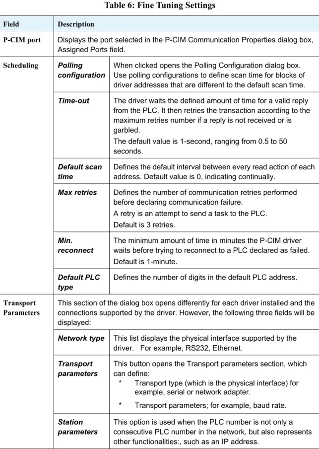
Table 6: Fine Tuning Settings
Field Description
P-CIM port Displays the port selected in the P-CIM Communication Properties dialog box, Assigned Ports field.
Scheduling Polling
configuration
When clicked opens the Polling Configuration dialog box. Use polling configurations to define scan time for blocks of driver addresses that are different to the default scan time.
Time-out The driver waits the defined amount of time for a valid reply
from the PLC. It then retries the transaction according to the maximum retries number if a reply is not received or is garbled.
The default value is 1-second, ranging from 0.5 to 50 seconds.
Default scan time
Defines the default interval between every read action of each address. Default value is 0, indicating continually.
Max retries Defines the number of communication retries performed
before declaring communication failure. A retry is an attempt to send a task to the PLC. Default is 3 retries.
Min. reconnect
The minimum amount of time in minutes the P-CIM driver waits before trying to reconnect to a PLC declared as failed. Default is 1-minute.
Default PLC type
Defines the number of digits in the default PLC address.
Transport Parameters
This section of the dialog box opens differently for each driver installed and the connections supported by the driver. However, the following three fields will be displayed:
Network type This list displays the physical interface supported by the
driver. For example, RS232, Ethernet.
Transport parameters
This button opens the Transport parameters section, which can define:
* Transport type (which is the physical interface) for example, serial or network adapter.
* Transport parameters; for example, baud rate.
Station parameters
This option is used when the PLC number is not only a consecutive PLC number in the network, but also represents other functionalities:, such as an IP address.
Defining Polling Configurations
Use polling configurations to define scan time for groups of addresses that are different to the default scan time. This is useful for reducing overflow and for defining higher priority addresses.
Polling block definitions are defined in the Add Polling Configuration dialog box. These definitions are displayed in the Polling Configuration dialog box.
• Accessing the Polling Configuration dialog box
1. In the P-CIM Configurator dialog box, click the Polling Configuration button.
2. The Polling Configuration dialog box has the following fields and buttons:
Table 7: Polling Configuration
Field Description
Block Block number. This field is automatically filled with a consecutive number.
PLC The number of the relevant PLC.
Start address The first address in the addresses block.
Quantity The total number of addresses in the addresses block.
Scan time Defines the interval between every read action for this block of addresses. This interval is different to the default scan time. The scan time is valid only when addresses are advised.
OnScan Defines that this block of addresses is constantly scanned according to the block’s scan time. This option can overload your system, therefore, only use it when necessary.
1. In this exercise you will assign a port to the Yogurt project and then define communication parameters for it.
2. Follow the instructions on page 49 and define a port using the following parameters: Port Name = 1 Driver Name = Modbus
3. In the Configurator dialog box select the following: Network type = RS232 4. Define the Transport Parameters as follows:
Transport type = COM port to which the RS232 cable is connected. 5. Define the other parameters according to the PLC definitions.
Add Opens the Add Polling Block dialog box where Polling Configurations can be defined.
Exercise – defining driver configurations
P-CIM Syntax for Driver Addresses
The format in which communication addresses are mentioned in P-CIM is driver dependent. Using direct access, P-CIM modules can retrieve raw data directly from communication drivers. Direct access addresses are referenced through dynamic data addresses by specifying the Server, Topic and Item as follows:
Examples:
• 2:4:40001:2 refers to bit 2 of register #40001 on PLC #4 that is connected to Port #2. • 1:1:10001 refers to input #10001 on PLC #1 that is connected to Port #1.
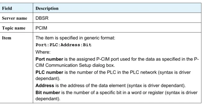
Table 8: Addresses Syntax
Field Description
Server name DBSR
Topic name PCIM
Item The item is specified in generic format:
Port:PLC:Address:Bit
Where:
Port number is the assigned CIM port used for the data as specified in the P-CIM Communication Setup dialog box.
PLC number is the number of the PLC in the PLC network (syntax is driver dependant).
Address is the address of the data element (syntax is driver dependant).
Bit number is the number of a specific bit in a word or register (syntax is driver dependant).
DDE is a Microsoft protocol that enables data exchange between two different programs. For example, P-CIM and Excel.
Checking Communications
Communications between P-CIM and the PLC are constantly tested during project development. Therefore, always check communications when you start to develop your project.
The following tools are used to check communications between the PLC and the PC: • Data Scope
• Alarm Summary
6.0.2 Data Scope
During project development the Data Scope can be used to monitor and modify values and status of up to 16 data items of a specific server and topic. This module can also be used after project development when installing and integrating the project in the workplace.
In the communications layer the Data Scope is used to: • Check communication between P-CIM and the PLC.
• Check and modify the values of data as quickly and efficiently as possible.
Working in the Data Scope
• Opening the Data Scope
In this exercise communication between P-CIM and the PLC are tested using the Data Scope.
1. Open the Data Scope.
2. In the Item field, type the first item address from the Item Addresses table. 3. Click OK.
Exercise - working in the Data Scope
Table 9: Item Addresses Table
Address Number
Item Addresses
1 1:1:40001
2 1:1:40001:1
3 1:1:1
• When the OK field is checked this indicates that the item is valid.
• The Server and Topic names are displayed in the Data Scope title bar. Server default name = DBSR Topic = PCIM.
4. Check that the Value field is filled and that the OK checkbox is checked.
5. In the Item field, insert the second and third item addresses from the Item Addresses table. 6. Click OK and check the results.
7. In the File menu select the Save option to save the items. These items are displayed the next time that the Data Scope is opened.
6.0.3 Alarm Summary - System Messages
System messages display events occurring in P-CIM modules. For example: • Success/failure status of module initialization.
• Communication between P-CIM and a device.
• Communication between P-CIM nodes (in a networked application).
• Viewing system messages
1. On your computer task bar, click the Alarm Handler icon and select Alarm Summary to display the System Messages window.
Scan, indicates that a database block is being scanned AEnb, indicates that a database block alarm is enabled
AAct, indicates that the alarm condition of a database block is active Ack, indicates that the database alarm has not been acknowledged OK, indicates that the item is valid
• The Value field is constantly updated with new values sent from the server.
• In the Options menu, select Always on Top to always display this window on top of other programs.
• When the Alarm Summary first opens on your screen, move the side ruler to the top to view all the system messages in the list. This list can be customized in the Options menu. For example, to display node numbers or to modify font type.
• During P-CIM startup Alarm Summary messages are renewed.
Previous messages can be viewed in the Daily Log. To view them, in the Alarm Summary window open the File menu and select the Show Daily Log option.
6.1 Communications Layer Troubleshooting
Error Messages Indicating Problems during Initialization of the Driver
Problem
The above messages indicate that the server cannot locate or has failed to open a COM port or that there is no COM port.
Workaround
Open the Driver Configurator dialog box and check that the defined COM port exists on your PC. Start up P-CIM.
Problem
The COM port is being used by another software program.
Workaround
Error Messages Indicating Writing to an Undefined Memory Range in the PLC
Problem
This error message is displayed when the requested PLC address is not defined in the PLC.
Workaround
Check if this address is defined in the PLC.
Error Message Indicating Communication Failure
Problem
This error message is displayed when the driver does not receive a response from the external device.
Workaround
Check the physical connections, such as the cable and power.
Check communication parameters in the Driver Configurator dialog box, such as COM port and baud rate.
This chapter discusses the variables that are created in aliases and used in the Yogurt project.
Chapter 7 Defining Data Items
In this chapter you will learn ….
• About the INI File Editor • About aliases
7.1 Aliases
• Aliases are text names used as shortcuts for addresses.
• Aliases should always be defined at the beginning of project development.
• When developing a project it is recommended to use aliases for textual names of addresses. Since aliases are easily replaced and modified, this saves time in project maintenance. • Aliases are saved under the project in the PFWALIAS.TXT file under the virtual Utilities folder. • After an alias is created it can immediately be incorporated into a P-CIM project.
• In the application an alias is held between the characters & &. For example,
the alias: &PcimPath& refers to: xx:\Pcim32\ where the P-CIM installation is saved. • An alias name can contain up to 255 characters and can include most printable characters
including spaces.
• An alias is not case sensitive.
• The following characters cannot be used: = ^ &
• P-CIM has a number of built in aliases, which can be viewed in the Syntax Manager when the Aliases option is selected.
7.1 INI File Editor
The INI File Editor can be used to create, modify and/or delete your project’s INI files and aliases. INI files hold P-CIM and P-CIM project parameters. In specific circumstances, these parameters can be modified in the INI File Editor.
• Accessing the INI File Editor
To open the INI File Editor, double click on the INI File Editor icon in the P-CIM Development
group.
• To add a section and token
1. In the Section field, type in the name of the new section. 2. In the Token field, type in the name of the new token. 3. In the String field, type in the name of the new string. 4. Click the Add Section button to add the section the INI file.
• To modify a token
1. Click the File Path bar and browse to select a Section. 2. Select the Token from the Settings list and update the string. 3. Click the Change button to update the string.
File Path, when clicked opens the Browse dialog box where another .INI file can be selected.
By default, the PFWALIAS.TXT file is displayed.
In this exercise you will define the aliases used in the Yogurt project using the information in the Aliases table.
1. Open the INI File Editor. By default, the PFWAlias.TXT opens displaying the Aliases section. 2. In the Token field, type in PLC.
3. In the String field, type in 1:1:
4. Click Add to add the alias to the Alias list.
5. Create all the aliases in the Aliases table using the information in the P-CIM Alias Name and Alias Reference columns.
Exercise - creating and testing an alias
Table 10: Aliases Table
P-CIM Alias Name Alias Reference Data Type Data Description
PLC 1:1: PLC number
Temperature 40001 Analog Temperature
SetTemp 40002 Analog Set temperature
Valve_ALM 40003 Analog Valve alarm
TLevel_1 40004 Analog Tank level for TK 1
TLevel_2 40005 Analog Tank level for TK 2
Pressure 40006 Analog Production line pressure
Tsouring_1 40007 Analog Souring agent
Tsouring_2 40008 Analog Souring agent
Tfruit_1 40009 Analog Fruit quantity
Tfruit_2 40010 Analog Fruit quantity
Cleaning 40011 Analog Cleaning quantity
Barcode 40012 Analog Flavor code
Valve_3V101 1 Digital Valve No: 3V101
Valve_3V102 2 Digital Valve No: 3V102
Valve_3V103 3 Digital Valve No: 3V103
Valve_3V201 4 Digital Valve No: 3V201
Valve_3V202 5 Digital Valve No: 3V202
6. Open the Data Scope and enter the following: &plc&&Temperature&. To view an alias in the Data Scope, in the Options menu select Alias Show.
TMix_1 11 Digital Mixer tank 1
TMix_2 12 Digital Mixer tank 2
CleaningAct 13 Digital Cleaning process
7.2 Syntax Manager
The Syntax Manager is a tool that holds the following information: • P-CIM system blocks, variables and functions.
• User defined aliases and blocks.
• Expressions, which are not discussed in this manual.
When an item is selected in the Syntax Manager the syntax that is used in the project for the item is displayed.
To access the Syntax Manager double click the Syntax Manager icon in the P-CIM Development
This dialog box has the following fields:
•
• Clicking F2 when working in any P-CIM module opens the Syntax Manager. • Selecting a field, clicking the Shift key and then pressing the Help button opens
P-CIM Help.
Table 11: Syntax Manager Module
Section Description
Syntax tool bar
When a button in this bar is clicked, it is added to the currently created item’s syntax.
Syntax separators
There are two syntax separators: , Comma that is used as a list separator.
; Semi-colon which is used as a commands separator.
Edit This section has the following options: Expression
DDE address Item
Workspace This section is used to create the item’s syntax.
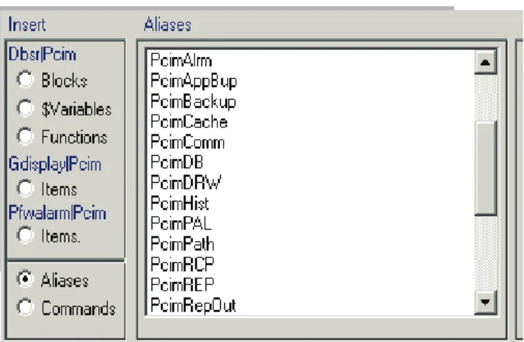
Insert The options in this section contain item types from different servers, and aliases and commands. When an option in this section is clicked its items list is
displayed.
Dbsr|Pcim When clicked displays the following items:
Blocks, when clicked displays the database server blocks defined by the user.
$Variables, when clicked displays database server $Variables.
Functions, when clicked displays database server functions.
Gdisplay|Pcim This option, when clicked displays Operator Workstation
items.
Pfwalarm|Pcim This option, when clicked displays Advanced Alarm server
items.
Aliases This option, when clicked displays user defined and built in
aliases.
Commands This option, when clicked displays commands, files and
dbase functions.
dBase functions
When checked this field displays built in application expressions. When an expression is selected, it can be added to the string and items in the workspace.
Description When an item is clicked its description is displayed in this field.
7.2.1
Syntax Legend
The following symbols are used in the Syntax Manager Description field.
To View the Aliases List in the Syntax Manager
1. Double click the Syntax Manager icon in the P-CIM Development group to open the Syntax Manager interface and then click Aliases.
Or,
2. Press the F2 key on your keyboard.
Apply When clicked, applies the content of the Edit section into the field of the dialog box from which the Syntax Manager was opened.
Table 12: Syntax Legend
Syntax Description
{} The information in these brackets is mandatory.
[] The information in these brackets is optional.
{XX|YY|ZZ|} Select one of the parameters in the brackets between each | separator.
[XX|YY|ZZ] Select one of the parameters in the brackets between each | separator.
DDE The DDE reference: SERVER|TOPIC|ITEM.
These symbols are not part of commands.
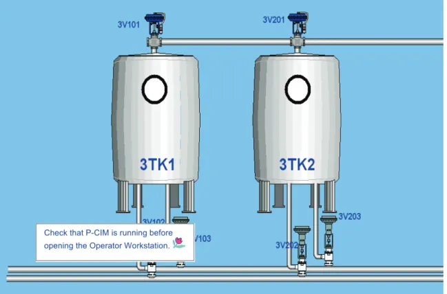
The Animation Editor is used to develop the graphical display of a P-CIM project.
A display is a collection of objects illustrating the plant floor and its devices. It can show data and can also receive operator input.
During runtime, the display is shown in the Operator Workstation on the operator’s station, and acts as an interface between the operator and the plant floor.
In this chapter the names OBJECT and GRAPHICAL OBJECT both refer to the image that is created in the Animation Editor interface.
Chapter 8 Animation Editor
In this chapter you will learn how to ….
* Create a new graphic display * Define display settings
* Draw objects and or add clipart objects * Add properties to an object
* Create and edit cells
* View the object in the Operator Workstation
Add $variables to objects Add properties to objects Create the graphical display
Add functions to objects
Open the Operator Workstation and check the display in runtime
8.1 The Animation Editor Interface
• Accessing the Animation EditorIn the P-CIM Development Group, double click the Animation Editor icon.
When first accessed the Animation Editor opens displaying the following: • Title bar, showing the name of the module, project, and display names • Menu bar, holding the Animation Editor menu options
• Toolbox, displaying the animation tools
8.1.1 Toolbox
The Toolbox is displayed when the Animation Editor opens. Its tools are used for creating the graphical display.
• The display name in the title bar is updated when you save your display.
• An * asterisk appears in the Animation Editor title bar after changes have been made in a display. The * disappears after the display is saved.
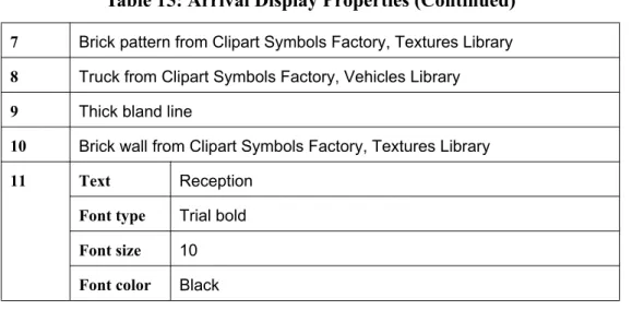
8.1.2 Selected Object Signs
When working in the Animation Editor you will see the following selection squares:
Table 13: Animation Editor Tools
Selection tool
Toggles between the Toolbox and the Clipart Library
Line tool
Square tool
Round edged square tool
Circle tool
Rotating tool
Zoom out tool
Restore zoom tool
Zoom in tool
Text tool
Color fill tool
Line style tool
Displays the current color/line/text selection
Line (L), Text (T), Background (B), and Fill (F) Color tool
Color palette
This square indicates a selected object without properties This square indicates a selected object that has properties
8.1.3 Creating a New Display
The first step in this stage of project development is to create a display:
• A display is created in an empty window where the objects representing the devices on the plant floor are drawn.
• Each display can have customized settings, for example; how it is opened in the Operator Workstation during runtime.
• To improve accuracy when drawing objects, a grid can be defined and displayed in the interface.
• The module’s status bar can be defined to display the type, size and location of selected objects.
In this exercise you will change the background color of the display. You will also add the Grid option to help you align objects as you work.
1. In the Animation Editor interface, select New to open a new display and then in the Display menu select Style to open the Display Style dialog box.
2. Change the background color of the display by clicking the Color button and then selecting any
This square indicates the object is a cell
3. Click OK to confirm and to exit the dialog box.
4. Add a grid to the display, from the Options menu select the Grid option and then define grid properties.
8.2 Drawing a Graphical Object
Graphical objects are either drawn using the toolbox tools or copied from the Clipart Library. Objects can be edited, cut/copied/pasted, rotated, resized, grouped and aligned.
8.2.1 Basic Information
Below is basic information that can help you to create your display.
• Selecting an object
Click the Selection tool in the toolbox and then click on an object. After the object is selected, it is surrounded by selection squares.
• Selecting multiple objects
Using the Selection tool either: • Draw around the objects.
• Hold the Shift key and then click each object. The selected objects are surrounded by squares.
• Saved objects
To save objects, from the File menu select either: • Save
• Save As • Save All
When a display is saved, two files are created: • DRW files holding graphics
• UPD files holding updated data
• Rotating an object
1. Select an object.
2. From the toolbox, select the Rotating tool. The selection action square appears in the middle of the object.
An * asterisk appears in the Animation Editor title bar after changes have been made in a display and disappears after the display is saved.
3. Place your cursor in the object next to the selection square and slowly turn the object.
• Copying, cutting, and pasting objects
Use the Edit menu options, right click menu, and/or Ctrl keys to copy/cut /paste objects.
• Grouping and ungrouping graphical objects
When working with many objects it is convenient to group all objects into one. 1. Using the Selection tool, draw around the objects of the group.
Or,
Using the Selection tool, hold the Shift button and click on each object in the group. The selected objects are surrounded by the multiple selection squares.
2. Either right click and select the Groups option or, in the Change menu select Arrange, and then select the Group option. The objects are grouped into one object.
3. To ungroup the group: Select the group, in the Change menu select Arrange, and then select the Ungroup option.
• Resizing objects
• To resize an object proportionally, select the object and then drag one of its corners either in or out.
• To change the objects width, select an object and then drag one of its sides either in or out.
A short cut to copying/pasting an object is to select the object, press the Shift button and to drag the object to another location where it is automatically pasted in.
An object looses all its properties when it is added to a group.
Not all Clipart buttons can be rotated.
up or down.
• Moving objects
To move objects either:
• Click in the middle of the object, and then drag it to a new location in the Animation Editor interface.
• Click in the middle of an object and press the Shift key. Your mouse curser changes into a
cross. Keep pressing the Shift key and then press the relevant direction arrows on your keyboard.
• Setting object order
Use this option to select a graphical object and to then send it to the back or front of a display. Select an object.
In the Change menu select the Order option and then either:
• Select Move to Front so that the object is displayed in front of other objects.
• Select Move to Back so that the object is displayed behind other objects.
•
• Aligning objects
When working in a display you can align objects automatically. 1. Select the objects to be aligned.
2. Either right click and select the Align option or, in the Change menu select the Align option to open the Align Objects dialog box.
To move more than one object:
ªSelect the objects and then click in the middle (of the selected objects) and drag them to their new location.
You can also select an object and then right click and select either Move to Back or Move to Front.