Multi-ute drill-broach for precision machining of holes
N. Dudak
a, G. Itybayeva
a, A. Kasenov
a;, Zh. Mussina
a, A. Taskarina
b,
and K. Abishev
ca. Department of Mechanical Engineering and Standardization, S. Toraighyrov Pavlodar State University, Lomov Street 64, Pavlodar, Kazakhstan.
b. Department of Metallurgy, S. Toraighyrov Pavlodar State University, Lomov Street 64, Pavlodar, Kazakhstan.
c. Department of Transport Engineering and Logistics, S. Toraighyrov Pavlodar State University, Lomov Street 64, Pavlodar, Kazakhstan.
Received 20 November 2017; received in revised form 30 November 2017; accepted 12 February 2018
KEYWORDS Multi-ute drilling process;
The quality of hole-making; Hole-enlarging; Hole surface microstructure.
Abstract. This paper deals with hole-enlarging multi-ute drilling process. In this respect, the analysis of existing structures, their advantages and disadvantages is carried out and investigated. Cutting conditions during hole-enlarging multi-ute drilling process are shown. Herein, a new design of a enlarging multi-ute drilling, as a hole-enlarging multi-ute drill-broaching tool from broaching-speed steel with carbide plates, and a new way of handling new tools are presented. Hole-enlarging multi-ute drill-broaching combines the features of hole-enlarging multiute drill (in cross-section) and those of broaching tool (in longitudinal section). In so doing, it is possible to increase the quality of hole-making (size variance, surface roughness) to facilitate cutting conditions and increase durability. The results of prototypes testing are presented in the end. © 2019 Sharif University of Technology. All rights reserved.
1. Introduction
The main objective of machinery development is to improve products' quality constantly [1,2]. A way to do so is to increase the accuracy of surface treatment, which directly aects the functional quality of the product.
Optimization process of broaching and reaming tools is continuous and uninterrupted. In this respect, one can see some recent publications: a paper dedi-cated to geometrical optimization of broaching tool [3];
*. Corresponding author. Tel.: 8-777-435-06-35 E-mail addresses: nikolaydns@mail.ru (N. Dudak); galia-itibaeva@mail.ru (G. Itybayeva);
asylbek kasenov@mail.ru (A. Kasenov); mussina zhanara@mail.ru (Zh. Mussina); aya taskarina@mail.ru (A. Taskarina); a.kairatolla@mail.ru (K. Abishev) doi: 10.24200/sci.2018.5623.1379
articles dedicated to the analysis of the distribution of forces in the process of holes machining [4-6]; U.S. Patent of a new broaching tool, about which there are many new patents issued every year concerning new designs of tools, and this particular patent is only an example of such a continuous process [7,8]. Articles dedicated to the analysis of the relationship of the cutting forces with the resulting surface quality.
As is observed, holes machining is a branch in which the search and optimization of existing ap-proaches continue and do not cease.
In the design of machine parts, one of the basic elements represents holes [9-11]. Depending on the requirements, the holes get drilling, reaming, unfolding, etc.
When countersinking, the cutting work is con-centrated on a relatively small length of the cutting part, up to 15 mm (Figure 1). The cutting part is often perceived as high mechanical and thermal stresses, leading to wear increase, low resistance of
Figure 1. Elements of cutting at hole enlarging. 1: hole-enlarging multi-ute drill; 2: blank; ': the main angle in the plan; a: thickness of cut; b: width of cut; t: depth of cutting; D: diameter of the hole; Do: diameter of
pilot hole; L: length of treatment; S: axis feed; Sz: feed
per tooth; and V : speed of cutting.
hole-enlarging multi-ute drilling, and, consequently, low machining accuracy and surface roughness of the hole [12-14].
There are various hole-machining methods: hon-ing operation, laser processhon-ing, and electro-chemical machining. Performing these methods requires ex-pensive purchase of some equipment. Hole-machining operation by a multi-ute drill-broach tool is carried out on a universal vertically oriented drilling machine, which does not require equipment costs. It is available in any machine-building enterprise.
The main advantage of the hole-enlarging multi-ute drilling is the ability to correct the hole axis and its shape.
Hole-enlarging multi-ute drilling process has a number of disadvantages: A high degree of the con-centration of cutting edges at the hole-enlarging multi-ute drilling provides cutting a large mass of metal [15-17]. This, in turn, increases the concentration of forces and temperature of cutting in the tool body that deteriorates the conditions of its work. The growth of forces leads to increased roughness of the surface and, sometimes, to the damage of the instrument. The growth in temperature increases the wear of the tool.
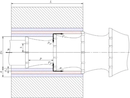
In terms of eccentric compression, all the core tools are used for holes' machining work, including the hole-enlarging multi-ute drills. At the core tools, the shank is located behind the instrument [18,19]. The application of core tools is based on pushing through the holes leading to additional radial forces and to the breakdown of the processing holes diameter under the action of axial cutting force (Figure 2).
To illustrate this situation, a scheme of complex diagrams of specic acting forces (Figure 3) arising
Figure 2. Scheme of axial force distribution on the cylinder of a standard hole-enlarging multi-ute drill.
Figure 3. Scheme of acting specic forces complex diagrams.
from the action of axial cutting forces on the taper shank is shown.
y =Paxisi ; (1)
where i is the number of selected points on the cone surface, varying from n1 to n2.
Paxis = n2
X
i=ni
Poy i; (2)
where Poy is specic axial force acting on selected
points, and Paxisis axial force acting at the shank end.
O-center compression and axis bending give rise to additional radial forces and to the breakdown of machined holes diameter. These eects also lead to the reduction of processing quality.
A cutting force arises when the broach teeth interact with the process material. It is divided into one acting along the direction of broach movement and into one perpendicular to such a direction.
In broaching, the round broach is under the stretching forces. Stretching force Pz is opposite to the
broach movement; stretching force Py is perpendicular
to the broach movement (Figure 4). These forces Pz and Py depend on the process material, cutting
thickness, cutting length, the number of chip grooves on a tooth, and front and back angles.
The total force Pz is composed of the specic
forces Pzi, mutually equilibrated in action on the
Figure 4. Scheme of forces acting in broaching. Diis broach teeth diameter; L is length of broaching; A is allowance; Sz is
advance per tooth; b is cutting edge width; p is tooth pitch; P is broaching force; Pyiand Pziare forces acting in broaching.
Based on Pz component, necessary stretching
force and the strength of broach elements (neck, cross-section along the rst tooth) are determined. Py
component squeezes the broach from the workpiece and aects accuracy in its size after broaching.
In broaching holes with round broaches, cutting force changes abruptly due to a variable number of si-multaneously operating teeth, in which pitch is usually not a multiple of workpiece lengths. After the time t equal to the ratio of cutting speed and teeth pitch t = V
p, the number of simultaneous operating teeth
decreases by one tooth, cutting force decreases and the tooth, leaving the surface of a workpiece, stops (in our case, this is the tooth no. 1). In case the latter happens, the next tooth, engaging with the surface of a workpiece (in our case, this is the tooth no. 5), comes into operation (Figure 5).
After the tooth no. 1 leaves the surface of the workpiece, broaching force is reduced by P
zi.
As a result, stress-strain state of a technological system is constantly changing. In addition, existing oscillations help reduce the surface quality (roughness and deviation from the specied geometric shape of a hole); moreover, broach resistance ability is re-duced.
To eliminate the above-mentioned drawbacks, a new metal-cutting tool has been developed and pro-posed for machining holes, hole-enlarging multi-ute drilling broaching. The proposed tool combines the advantages of a drill, e.g., self-centering and alignment correction holes of complex prole and broach, and
Figure 5. Scheme of broach teeth operation. L is length of broaching, P0 is tooth pitch; P0 is distance between
the workpiece and the next tooth no. 5.
then, a favorable distribution of the forces in the body of the tool eliminates the beating and contributes to the high accuracy of the resulting hole. It provides improved cutting conditions, self-centring by dragging the tool through the hole, xes shank front location, and increases the stability of the process.
Broach reamer is recommended to machine cylin-drical holes of up to 40 mm in diameter and two diameters in length with accuracy rate about 6-7 points for the rough surface Ra = 0:08 0:16 m and with
allowance equal to the allowance for processing with reamers [20].
Hole-enlarging multi-ute drill-broach is recom-mended to machine cylindrical holes over 40 mm in
diameter and up to two diameters in length in materials subjected to hardening with accuracy rate of about 7-8 points for rough surface Ra = 0:16; ; 0:32 m and with an increased allowance up to 0.8-1.0 mm.
Hole-enlarging multi-ute drill-broach is designed to remove more allowance in comparison with the broach reamer '1\'2, where '1 is cone angle of a
broach reamer and '2 is cone angle of a hole-enlarging
multi-ute drill. 2. Method
Methodological bases of research include dialectical and subject-activity approaches, methods of episte-mological explication, conceptualization, methodolog-ical analysis, modeling, idealization, and structural-functional analysis.
To achieve this goal, methods of mathematical statistics and statistical modeling have been used. The experience of domestic and foreign scholars on the subject was summarized.
To verify the obtained results, an experiment was conducted, in which objects under study were delivered in a special, controlled and managed conditions. It gave an opportunity to consider the object of study and to obtain its full characterization.
Studies in this area began in 2008 and continued to date.
2.1. Scheme of the hole-enlarging multi-ute drill-broach operation and description of the design
The new cutting tool for machining holes is based on the combination of several types of operations in one, i.e., drilling and broaching. The use of new designs of reamers, called hole-enlarging multi-ute
drills-broaches, eliminates negative factors of machining holes with existing hole-enlarging multi-ute drills and improves the quality and accuracy of holes machining and tool's life service.
Hole-enlarging multi-ute drill-broach, in which hole-enlarging multi-ute drill and broach properties combined in a single tool is designed to handle details such as sleeves, plugs, rings, etc. in the standard, large-scale and mass production by 7 to 8 of IT Grade. Preliminary patents of the Republic of Kazakhstan have been received [10,21,22].
Hole-enlarging multi-ute drill-broach is con-structively built on the following principle; in axial section, it has structural features corresponding to the broach: front shank, neck, front and rear alignment, cutting and calibrated parts (they have helical teeth, and the cutting part has a conical shape, and the calibrating one has a cylindrical shape and extends through the hole as a broach) and, in a cross-sectional part, it has hole-enlarging multi-ute drilling features: the shape and number of teeth, the geometry of the cutting part (Figure 6); the proposed tool rotates during processing as the hole-enlarging multi-ute drill. Thus, the new tool is named hole-enlarging multi-ute drill-broach.
Figure 7 shows the cross-sectional prole and the shape of hole-enlarging multi-ute drill-broach teeth in the normal cross-sectional prole of cutting portion (versions 1, 2, 3) and of sizing part - version 4. In the cross-section, the prole of hole-enlarging multi-ute drill-broach helical teeth can be of the following ver-sions: standard prole of teeth (versions 2 and 3) and xed width prole of teeth (version 1). Application of a xed width prole of teeth will increase the resistance of hole-enlarging multi-ute drill-broach as well as the number of regrinding and, consequently, increase the
Figure 6. Structural elements of hole-enlarging multiute drill-broach. dfr:sh: and dre:sh:: diameters of the front and rear
shank; dfr:pil:: diameter of the front pilot; dsiz:part: diameter of the sizing part; dre:pil:: diameter of the rear pilot; `fr:sh:
and `re:sh:: lengths of the front and rear shank; `neck: neck length; `fr:pil:and `re:pil:: lengths of the front and rear pilot;
`ann:groove:: length of the annular groove; `cut:part:: length of the cutting portion; `siz:part:: length of sizing part; L: length
of hole-enlarging multiute drill-broach, !: angle of spiral leads, direction like cutting direction; to: axial step of hole-enlarging multiute drill-broach; 1: front shank; 2: neck; 3: front pilot; 4: an annular groove; 5: cutting portion; 6: chip-breaking groove; 7: clearance groove; 8: sizing part of hole-enlarging multiute drill-broach; 9: rear pilot; and 10: rear shank.
Figure 7. Cross-sectional prole of hole-enlarging multiute drill-broach. : front corner; : back angle; and : the angle of the tooth back ( = ).
Figure 8. Cross-sectional prole of hole-enlarging multi-ute drill-broach with hard alloy plates. 1: hard alloy plate; : front corner; and : back angle.
service life due to regrinding ank surface, as opposed to the hole-enlarging multi-ute drill-broach with a round tooth compared with hole-enlarging multi-ute drill with a wire screw tooth, and recreate the state of the rear surface after regrinding to the state of a new instrument that will lead to higher quality of treatment. All the versions (1, 2, 3, and 4) can be refaced on the ank surface.
As a material for cutting, part of hole-enlarging multi-ute drill-broach can be as high speed as steel R6M5, R18, and soldered carbide plates. Cross-sectional prole is presented in Figure 8.
Hole-enlarging multi-ute drill-broach concludes in its design elements of a hole-enlarging multi-ute drill and a broach, whose combination creates condi-tions that are more favorable for cutting. The cutting work is distributed along the long cutting part, as in broaching with a screw tooth, the shape of the teeth in the cross section with the prole of the chip groove, as well as working movements (a combination of rotational and translational movements)- as in the countersink. The design of hole-enlarging multi-ute drill-broach has such advantages of the broach as a relatively low cutting speed, processing quality (dimen-sional accuracy, surface roughness, and the reduction of abrasion), while the number of grooves as at the hole-enlarging multi-ute drill from 2 to 6 depending on the diameter of the treatment.
Machinery parts' holes processing by the hole-enlarging multi-ute drill-broach are performed on a lathe in the following ways: xing hole-enlarging
multi-Figure 9. Distribution of forces by the holes processing with hole-enlarging multiute drill-broach.
ute drill-broach in the cartridge or on the support of the lathe to the left or right direction depending on the direction of spindle rotation with the cutting tool.
In the design of the hole-enlarging multi-ute drill-broach, the shank is located at the front and the tool is pulled through the hole, eliminating breakdown of holes, followed by treatment with pushing the tool through the hole (Figure 9).
Thus, good centering of hole-enlarging multi-ute drill-broach and improvement of the quality of hole machining are achieved. In view of the above, the scheme of cylindrical holes processing is developed. At the front of the tool, the shank is located, eliminat-ing the eccentric bendeliminat-ing, because the hole-enlargeliminat-ing multi-ute drill-broach is pushed through the hole.
In the process of pushing with the hole-enlarging multi-ute drill-broach through the hole, this tool is centered, and its bending and axis withdrawal are excluded that improve the quality of holes processing. When machining by the proposed method, the tool is given a relative longitudinal movement as when pulling or the workpiece is given a longitudinal movement that
relatively corresponds to pulling. Either hole-enlarging multi-ute drill-broach or workpiece is given a rotary motion inherent to the hole-enlarging multi-ute drill, which corresponds to reaming.
When processing with the hole-enlarging multi-ute drill-broach, the following movements are used simultaneously:
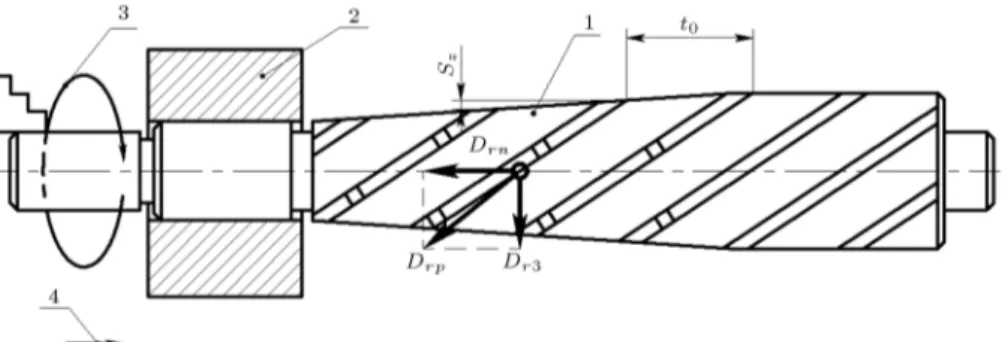
1. A longitudinal movement along the axis (of work-piece or tool), which is inherent in broaching as the main cutting motion, denoted by Drn;
2. Rotational motion inherent to reaming, denoted by Dr3 (Figure 10).
When developing a new way, the synthesis of two processing methods has been performed:
1. Reaming with the main cutting motion Dr by the
rotation of hole-enlarging multi-ute drill or a part and axial feed of hole-enlarging multi-ute drill or a part D;
2. Broaching with the main movement of cutting Dr{
translational motion of the tool and constructive feed Sz.
At the same time, in view of the constructive ling for hole-enlarging multi-ute drill-broach, feed movement of hole-enlarging multi-ute drill has become one of the main components of the resultant cutting motion. Constructive feed of hole-enlarging multi-ute drill-broach is done at the expense of the conical shape of working part with spiral teeth. With this arrangement, the supply is carried out continuously.
When processing with the hole-enlarging multi-ute drill-broach, the feed motion of the tool is not available and is replaced by constructive feed for stock removal in the radial direction, as when broaching.
The teeth direction of the hole-enlarging multi-ute drill-broach and a hole-enlarging multi-multi-ute drill always coincide with the cutting direction and varies depending on the direction of rotation of the workpiece or tool during machining.
The combination of direct (right) rotational mo-tion of the workpiece and translamo-tional momo-tion of the hole-enlarging multi-ute drill-broach creates working conditions, and combination of the relative motion of the hole-enlarging multi-ute drill-broach and the workpiece, as during reaming holes, provides unifor-mity of teeth direction.
When machining by the proposed new method, the instrument is given a longitudinal movement or the workpiece is given a longitudinal displacement that corresponds to the broaching process. Rotary motion inherent in hole-enlarging multi-ute drill is given to hole-enlarging multi-ute drill-broach or to the workpiece that corresponds to reaming. The combination of rotational and translational motions is such that the tool always approaches the workpiece on the screw thread \ram" tooth from the obtuse angle between the cutting edges of the teeth and the axis of the hole-enlarging multiute drill-broach; moreover, for the tool, the conditions for work of the hole-enlarging multi-ute drill and the hole-enlarging multi-ute drill-broach are enabled. The direction of helical teeth is similar to the cutting direction; a sectional shape of the chip groove (teeth) coincides with the shape of chip grooves of the hole-enlarging multi-ute drills; the number of teeth is in accordance with the requirements of the standard (Figure 11).
The axial broaching force value of hole-enlarging multi-ute drill is constant P = const. The cutting process is accompanied by a rotational movement Mk depending on the machining technique; bending
moment Mu appears due to drill axis bending.
Dierential equation for hole machining with a hole-enlarging multi-ute drill-broach will be:
m@@t2x2 + @x@t + cx +2(Mkd+ Mu)= F: (3) The constant broaching force is an advantage of hole machining with helical broaches based on helical teeth P = const. Consequently, force developed by operating cylinder is also constant, F = const.
Figure 10. Scheme of the main cutting motions. 1: hole-enlarging multiute drill-broach; 2: workpiece; 3: rotational motion in the designated point A gives the cutting motion inherent to reaming; 4: the progressive movement of the workpiece, causing the cutting force along the axis of the hole-enlarging multi-ute drill-broach and propelling the cutting inherent in broaching; Sz: feed per tooth; to: axial spacing between the teeth.
Figure 11. Hole-enlarging multiute drill-broach.
Then the dierential equation (3) will be as F > P = cx:
m@2x @t2 +
@x
@t + cx = F: (4)
Equation of motion of a point on the cutting edge of a broach with helical teeth shows that there must be tangential and additional axial forces due to helical teeth. Thus, a rotational moment takes place.
Then, the dierential equation (4) will be as follows:
m@2x @t2 +
@x @t + cx +
2Mk
d = F; (5)
where d is the diameter of a broach, Mkis the rotational
moment, and Mk has an additional eect on the
broached workpiece.
In hole machining with a hole-enlarging multiute drill-broach, axial force is equal to Poc. It is lower than
the force acting on the trip spindle of lathe F , F > P . Force Poc is an additional axial force, performing
thanks to helical teeth of a hole-enlarging multi-ute drill-broach.
If the rotational moment caused by helical teeth of a hole-enlarging multiute drill-broach is taken into account, dierential equation for machining with a hole-enlarging multiute drill-broach countersink-broach will be:
m@@t2x2 + @x@t + cx = F Poc: (6)
The dierential equation will be transformed, introduc-ing the followintroduc-ing notations Tk=pmc; Tg= c; K = 1c;
then: T2 k@
2x
@t2 + Tg
@x
@t + x = K:(F Poc): (7) Machining involves all the conditions for broaching holes with a helical broach.
To nd the transient process for the case when Tg 2Tk, let us form a characteristic equation:
T2
kp2+ Tgp + 1 = 0: (8)
Its solution is in the following:
Figure 12. Graph of transient process.
P1;2= Tg
p T2
k 4Tk2
2T2
k : (9)
The general integral for Tg> 2Tk is:
xn= c1e p1t+ c2e p2t: (10)
The steady-state value is xy = K(F Poc), because @x
@t = 0 and @
2x
@t2 = 0.
The complete solution to the dierential equation: x = xn+ xy= C1e P1t+ K(F Poc): (11)
Integration constants C1 and C2 are determined
con-ventionally from initial conditions when t = 0; x = 0; and @x
@t = 0.
The graph of transient process consists of two exponents with a ex point n (Figure 12).
The nature of transient processes and their du-ration depends on values Tk and Tg that include the
system parameters.
Unlike the hole enlarging with a standard drill, the same process with a hole-enlarging multi-ute drill-broach is more stable, because a drill is self-aligning in the hole during the \broaching". Equation solution shows that the system is stable, as can be seen from the graphs of transient process.
The developed mathematical model, describing the process of hole machining with a hole-enlarging multi-ute drill-broach, allows the calculation of the system parameters to solve the problems of mechanical design and machining technologies.
2.2. Experimental studies on hole-enlarging multiute drill-broach processing
Hole machining was carried out on the screw-cutting lathe of model 1A616, and geometric accuracy assess-ment was carried out in accordance with the GOST standard 18097-93 by the Euro-Asian Council for Stan-dardization, Metrology and Certication (EASC). For the experiments, samples of parts were prepared. The samples were drilled with a diameter equal to that of the front rail of the hole-enlarging multi-ute drill-broach (Figures 13 and 14).
Processing with hole-enlarging multi-ute drill-broach was done using cooling lubricants. When processing the steel, a 10% solution of the emulsion was used as a lubricating and cooling liquid; in the treatment of bronze and iron, a 10% solution of the emulsion and kerosene was used. Adding kerosene is a common practice used in drilling, which provides high drilling rates and a reduction in dierential sticking.
Figure 13. Free position of a hole-enlarging multiute drill-broach.
Figure 14. Terminal position of a hole-enlarging multiute drill-broach.
Conducting experiments are associated with the determination of the minimum necessary, but sucient number of experiments. To solve this problem, the mathematical apparatus of full-factorial experiment is applied by type 23 [23].
The procedure for conducting experiments has been selected to be able to estimate the random errors of the experiment and avoid the eect of possible systematic errors. Identifying accidentally interfering factors, whose eect may be systematic, allowed the principle of randomization, which is used in the imple-mentation of the matrix for experimental design.
To assess the reproducibility of experiment G, Cochran's C test was used [24]. The experiment is reproducible, as Gmax= 0:537 < Gtab= 0:7679.
The experimental data were processed with the Excel program.
The adequacy assessment of the obtained regres-sion equations was performed using Fisher's exact test (F = 1:441 < FT = 5:32).
By transforming the regression equation, empiri-cal relationships were derived:
1. The surface roughness:
Ra= 0:1487 + 0:0004n 0:109S:
2. The depth of the surface defect layer: h = 1:15 + 0:032n 11:364S:
3. Surface hardness:
HB = 126:3 + 0:099n 60S:
4. The diameter deviation:
= 19:793 + 0:000186n 0:0455S: 3. Results and discussions
The main characteristic of the multi-ute drill-broach is a compound of the multi-ute drill and the broach features in one tool. This factor improves cutting conditions.
The results of the samples testing treated with the new cutting tool, i.e., hole-enlarging multi-ute drill-broach, and a new way of processing are as follows:
- The accuracy of the diametrical size of the holes is 0:018 0:033 mm (7-8 IT Grade);
- The surface roughness of the holes is in the range of Ra = 0:16 0:32 m, which corresponds to 9 and
10 grades of roughness.
Analysis of the results shows that the precision of holes diametric sizes after the treatment with hole-enlarging multi-ute drill-broach increased by 1, 2 IT
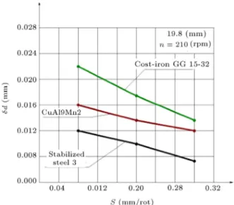
represent the speed eect and feed on the breakdown of the holes diameter with hole-enlarging multi-ute drill-broach. Figures 15 and 16 are graphs of the precision of diametric dimensions of speed and feed to handle openings diameter 19:8 mm.
As can be seen from the graphs, the diametrical size deviation increases with rotation frequency and decreases with increasing feed. This is due to the fact that the processing holes with the multi-ute drill-broach are close to drill-broaching process.
Figure 15. Graph of diametrical size accuracy dependence on the rotation frequency for processing diameter 19:8 mm.
Figure 16. Graph of diametrical size accuracy dependence on the feed for processing 19:8 mm.
radically solve many problems of tool wear because the geometry of the proposed instrument and, con-sequently, forces and cutting forces contribute to less intense conditions for the operation and performance of instruments. In other words, the tool geometry allows, based on already known and proven structural materials, to provide tools with greater service life. Moreover, due to better distribution of forces in the tool; beats reduce drastically and results improve quality of material treatment, reduce roughness, and improve alignment holes complex prole of processing quality in general.
After machining with a hole-enlarging multi-ute drill-broach, the hole surface microstructure was determined according to the procedure. The
pol-Figure 17. Graph of the roughness dependence on the speed machining of holes 19:8 mm.
Figure 18. Graph of the roughness dependence on the feed in the processing holes 19:8 mm.
Figure 19. Microstructure of a sample no. 4, machined with a hole-enlarging multiute drill-broach 200.
Figure 20. Microstructure of a sample no. 4, machined with a hole-enlarging multi-ute drill-broach 100.
ished section was studied with a OLYMPUS BX2M metallographic microscope for surface microstructures (Figures 19 and 20).
4. Conclusion
The quality and productivity of the holes machining process heavily depend on the tool design, which denes the cutting conditions. A procedure is described for an optimal design of the new multi-ute drill-broach tool.
To sum up, experimental studies show that the processing of holes with the multi-ute drill-broach provides higher quality of holes surface, decreases roughness, depth of the defect layer, a breakdown of the holes. This is due to benign cutting conditions in comparison with standard multi-ute drill. Due to the taper cutting part of the multiute drill-broach, a constant pulling force eliminates the cutting process's
continuity inuence, reduces the overall length of the simultaneous cutting edges of the teeth; moreover, as a consequence, the tool life has increased by 2-3 times compared to a standard multi-ute drill.
Analysis of the results shows that the diametrical size accuracy of holes after the treatment with the multi-ute drill-broach has increased by 1 and 2 quality grade compared to broaching; roughness has decreased by 1 and 2 grade.
Analysis of the above graphs allows for opti-mal selection of processing modes for high-precision parts (accuracy of geometric dimensions, the minimum roughness is provided at relatively low speeds and high feed rates, and the depth of the defective layer increases with increasing speed and decreases with increasing tool feed).
Microstructure analysis of samples, machined with a hole-enlarging multiute drill-broach, showed that inner surface has areas with a deformed layer, whose maximum depth is 25 m. This is a ferrite-pearlite microstructure.
Acknowledgements
This study is part of a grant under the Young Sci-entist Program of the S. Toraighyrov Pavlodar State University on topic no. C1 \Determination and desig-nation of cutting modes for machining holes with new cutting tools" order no. 1-02-07/683 dated 11/23/2009. Research continues to date within the initiative-search topic \Research and development of resource-energy-saving metal-cutting tools" from its own funds, which is registered in the National Center of Science and Technology Evaluation JSC (Kazakhstan) registration number 0117PKU0382, 2017.
References
1. Webzell, S. \Analysis of factors aecting the tool life", Metalwork. Prod., 150, pp. 65-66 (2006).
2. Wang, Y.J., Zhang, D.H., Wu, F.J., Yao, K., and Hou, Z.M. \Simulation of cutting force based on software deform ICICTA: 2009", In Second Int. Conf. Intell. Comput. Technol. Autom., pp. 224-227 (2009).
3. Vogtel, P., Klocke, F., Lung, D., and Terzi, S. \Au-tomatic broaching tool design by technological and geometrical optimization", Procedia CIRP, 33, pp. 496-501 (2015).
4. Vogtel, P., Klocke, F., Puls, H., Buchkremer, S., and Lung, D. \Modelling of process forces in broaching inconel 718", Procedia CIRP, 8, pp. 409-414 (2013).
5. Goncalves, D.A. and Schroeter, R.B. \Modeling and simulation of the geometry and forces associated with the helical broaching process", Int. J. Adv. Manuf. Technol., 83, pp. 205-215 (2016).
integrity", CIRP Ann. - Manuf. Technol., 61, pp. 107-110 (2012).
8. Klocke, F., Gierlings, S., Brockmann, M., and Veselo-vac, D. \Force-based temperature modeling for surface integrity prediction in broaching nickel-based alloys", Procedia CIRP, 13, pp. 314-319 (2014).
9. Lazarev, D.E. and Nasad, T.G. \Cutting tools for improving the quality and productivity of precise holes machining", Mach. Tools., 1, pp. 14-17 (2014).
10. Dudak, N.S., Itybaeva, G.T., Kassenov, A.Z., and Mussina, Z.K. \Part of the 14th Nechnike Sciences", In Proc. IV Int. Sci. - Pract. Conf. \Scientic Ind. Eur. Cont. - 2008", Publishing House <<Education and Science>>, Prague, pp. 67-71 (2008).
11. Beju, L.D., Br^ndasu, D.P., Mutiu, N.C., and Roth-mund, J. \Modeling, simulation and manufacturing of drill utes", Int. J. Adv. Manuf. Technol., 83(9-12), pp. 2111-2127 (2016).
12. Gupta, K.K., Jain, T., and Deshmukh, M. \Optimiza-tion of process parameters in high rpm micro drilling machine", Int. J. Innov. Eng. Technol., 2, pp. 128-130 (2013).
13. Zhao, C., Liang, Z., Zhou, H., and Qin, H. \In-vestigation on shaping machining method for deep hole keyway based on on-line symmetry detection and compensation", Journal of Mechanical Science and Technology, 31(3), pp. 1373-1381 (2017).
14. Kwon, K.B., Song, C.H., Park, J.Y., Oh, J.Y., Lee, J.W., and Cho, J.W. \Evaluation of drilling eciency by percussion testing of a drill bit with new button arrangement", International Journal of Precision En-gineering and Manufacturing, 15(6), pp. 1063-1068 (2014).
15. Bulat, P. and Volkov, K. \Detonation jet engine. Part 1 - Thermodynamic cycle", Int. J. Environ. Sci. Educ., 11, pp. 5009-5019 (2016).
16. Bulat, P., Volkov, K., and Ilyina, T. \Interaction of a shock wave with a cloud of particles", IEJME-Mathematics Educ., 11, pp. 2949-2962 (2016).
17. Baroiu, N., Berbinschi, S., Teodor, V., and Oancea, N. \The modeling of the active surfaces of a multi-ute helical drill with curved cutting edge using the SV& Toolbox environment", in: Proc. 13th Int. Conf. Tools-ICT, Miskolc, pp. 259-264 (2012).
20. Dudak, N.S., Kasenov, A.Z., Musina, Z.K., Itybaeva, G.T., and Taskarina, A.Z. \Hole-making with the use of reaming and broaching tool", Life Sci. J., 11, pp. 282-288 (2014).
21. Byrne, G. \Current state of various materials cutting technology and its practical application area", Ann. CIRP., 52(2), pp. 483-507 (2003).
22. Benes, J. \Overview of cutting tools", Am. Mach., 6, pp. 18-20 (2007).
23. Fisher, R. \The Arrangement of eld experiments", J. Minist. Agric. Gt. Britain., 33, pp. 503-513 (1926).
24. Cochran, W.G. \The distribution of the largest of a set of estimated variances as a fraction of their total", Ann. Hum. Genet., 11, pp. 47-52 (1941).
Biographies
Nikolay Dudak has been a PhD candidate of Engi-neering Sciences. Now, he is a Professor at the Me-chanical Engineering and Standardization Department in S. Toraighyrov Pavlodar State University.
His main works was \TRUE LIC N.K. REERH", which was printed in Pavlodar, S. Toraighyrov. Also, in co-authorship with Janushkin, As in 2011, he wrote next work \Method and cutter head for high-performance face high-performance of holes". Besides, he has three self-written works \Cosmic morality, the cosmic knowledge of unity and brotherhood", \A true world view is the epistemological basis of secular education of morality" and \Thin-energy-information Basis and Beauty of Life and Evolution".
Galiya Itybaeva has been a PhD candidate of Engi-neering Sciences. Now, she is an Associate Professor at the Mechanical Engineering and Standardization De-partment in S. Toraighyrov Pavlodar State University. Her main works were written in co-authorship and called \Processing of holes with a reamer-broach" (2014) and \Hole machining based on using an incisive built-up reamer" (in 2017).
Asylbek Kasenov has been a PhD candidate of Engi-neering Sciences. Now, he is an Associate Professor at the Mechanical Engineering and Standardization De-partment in S. Toraighyrov Pavlodar State University. His main works were written in co-authorship and called \Control holes with calibers" (in 2013); \Review and analysis of the capabilities of applica-tion programs" (in 2017); \Processing of holes with a reamer-broach" (in 2014); \An issue of intelligent
road transport in Kazakhstan" (in 2017); and \Hole machining based on using an incisive built-up reamer" (also in 2017).
Zhanara Mussina has been a PhD candidate of Engi-neering Sciences. Now, she is an Associate Professor at the Mechanical Engineering and Standardization De-partment in S. Toraighyrov Pavlodar State University. Her main works were written in co-authorship and called \The use of magnetic phenomena in non-destructive control" and \Hole machining based on using an incisive built-up reamer".
Aizhan Taskarina holds a PhD degree and works as an Associate Professor at the Metallurgy Department in S. Toraighyrov Pavlodar State University.
Her main works were written in co-authorship
and called \Physical phenomena in the tool zone during the hole-making operations of the tool slide built-up reamer" (in 2014); \The method of nish-ing turnnish-ing billets with an inclined axis through a continuous saber cutter" (in 2014); \The design of broaching prole cutting with screw-like equal teeth" (in 2014); \International scientic conference of young scientists, undergraduates, students and schoolchil-dren \XV Satpayev readings"" (in 2015) and \Ma-terials of the X international scientic and practical conference \Conduct of modern science-2014"" (in 2014).
Kairatolla Abishev has been a PhD candidate of En-gineering Sciences. Now, he is an Associate Professor at the Transport Equipment and Logistic Department in S. Toraighyrov Pavlodar State University.