Sharif University of Technology
Scientia IranicaTransactions B: Mechanical Engineering http://scientiairanica.sharif.edu
High-performance controller design and evaluation for
active vibration control in boring
P. Naeemi Amini and B. Moetakef-Imani
Department of Mechanical Engineering, Ferdowsi University of Mashhad (FUM), Mashhad, P.O. Box 9177948974, Iran. Received 7 February 2018; received in revised form 3 May 2018; accepted 16 July 2018
KEYWORDS High-performance controller; Active control of chatter;
Machining dynamics; Internal turning; Direct velocity feedback; Optimized gain selection.
Abstract. High-quality manufactured components with a fast production rate represent an increasing demand of the modern machine tool industry. Internal machining operations due to the large length-to-diameter ratio are highly prone to intolerable chatter vibrations and have proven to be an extremely challenging process. This paper presents a new method for a proper design of Direct Velocity Feedback (DVF) controller in order to extend the boundaries of stable cutting for internal turning with minimum control eort. Control eort and active damping performance are two counteracting parameters that aect the results of active vibration control. After properly implementing the DVF active control algorithm on the internal turning setup, stable boundaries for dierent control gains of DVF controller are thoroughly studied. The comparison shows that although high DVF gains may considerably improve dynamic stiness of the tool, it leads to maximum control eort and actuator saturation and, consequently, process instability. The proposed gain selection method results in a signicant increase in stable machining over the desired range of cutting conditions. The suggested design approach of the DVF controller can considerably improve the limitations of rough machining on long overhang boring bars.
© 2019 Sharif University of Technology. All rights reserved.
1. Introduction
Unique components in industries are made of hard-to-cut materials and have features that require specic tools with a large length-to-diameter ratio (L=D). These tools are susceptible to chatter vibrations, and their productivity is relatively restricted due to exces-sive exibility. For instance, for a large L=D higher than 8, metal removal is practically impossible. In a stable cutting process, vibrations are attenuated, resulting in smooth surface nish (see Figure 1(a)). However, once self-excited chatter vibrations occur, *. Corresponding author.
E-mail address: [email protected] (B. Moetakef-Imani) doi: 10.24200/sci.2018.50411.1684
the amplitude of vibrations increases uncontrollably, leading to a poor surface nish (see Figure 1(b)). In this situation, vibrations generate undesirable results such as worse dimensional accuracy, noise, and even tool breakage [1]. Therefore, the development of new tools for vibration-free machining with desired surface nish and greater metal removal is required.
Selection of the machining parameters for sustain-ing a stable cuttsustain-ing is generally based on the classical stability lobe diagram that provides boundaries of stable cutting. The critical depth of cut is directly related to the dynamic stiness of the structure; hence, increasing the damping of the tool structure will increase the critical depth of cut [2]. Enhancing the dynamic stiness of the tool structure reduces the chatter vibrations and increases the stability limits of the cutting operation and, therefore, productivity.
Figure 1. Eect of changing length-to-diameter ratios on stability of internal turning.
Many research projects that focus on developing new tools for chatter control can be categorized into two approaches: 1) oine or passive control and 2) online or active control [3].
In passive vibration control approaches, the struc-ture is usually equipped with a tuned-mass-damper system with a pre-assigned natural frequency and a damping ratio. The main objective of these methods is to increase the damping of the critical mode of vibration by energy dissipation without any external power supply. In these methods, the optimum TMD parameters are chosen with the prime aim of increasing the value of the negative real part of FRF [4].
Passive vibration absorbers have been extensively studied in the literature. Tarng et al. [5] proposed a vibration absorber to modify the FRF of the cutting tool and achieve the desired behavior. Theoretical and experimental results showed improvements in cutting stability limits.
Miguelez et al. [6] studied the behavior of boring bars with a passive vibration absorber for chatter sup-pression. Two analytical approaches for determining optimum parameters of the absorber were compared. The design procedure for vibration absorber was suc-cessfully applied to a practical example. Yang et al. [7] presented a numerical optimization method for tuning parameters of multiple TMDs in order to
increase chatter stability. Optimized TMDs attached to the machine structure increased stability limits of the turning process.
Passive vibration damping techniques show good advantages; however, their performance is restricted by the tuning accuracy of the dampers, which is extremely dicult due to uncertainties. Moreover, damping and stiness values of passive dampers are xed once adjusted. However, by changing applications, they may need to be retuned or even replaced [8].
On the other hand, active control methods are implemented by introducing an external control force to the structure by means of an actuator in order to achieve better dynamic performance. Although the active vibration control is complex and needs a high degree of expertise to implement, the approach can be used for various types of machine tools and dierent cutting conditions. In fact, the damping ratio of the vibratory system is remarkably enhanced. In addition, multiple modes of vibrations can be taken into consideration [9].
Tewani et al. [10] studied a long boring bar with an embedded piezoelectric actuator. This patented active dynamic absorber could also be used as an active proof-mass damper. Two dierent control strategies including acceleration and velocity feedback control and Linear Quadratic Regulator (LQR) control were considered for the active dynamic absorber. Exper-imental results displayed a signicant reduction in the amplitude of vibration using the proposed active dynamic absorber.
An adaptive vibration control technique using ltered-X least mean square algorithm was proposed by Andren and Hakansson [11] for chatter suppression in boring bars. A piezo ceramic actuator was installed on a standard boring bar for vibration control. The embedded actuator was placed within the surface boundary of the boring bar. Experimental results of boring operations showed that the amplitude of the fundamental natural frequency, which was related to the bending mode, could be reduced to 40 dB.
Matsubara et al. [12] designed a hybrid absorber using piezoelectric actuators and an LR circuit. The parameters of the LR circuit were derived analytically to optimize the real part of the compliance. Machining test results proved that the chatter vibration could be reduced by the proposed hybrid absorber in two directions.
In all of the reviewed active control methods, piezoelectric actuators were installed inside boring bars for chatter suppression by applying actuating force in the axial direction. While the size of actuators is limited by the boring bar geometry, achieving a better active damping performance has been the main purpose [13].
are usually located in the path of transmitting cutting forces of the structure. Hence, in heavy duty cutting operations, large stiness is required for these elements. In the other approaches, the static stiness of the original structure is retained since the active vibration absorbers are located out of the structure.
Pratt and Nayfeh [14] developed a nonlinear model to analyze the active control of cantilever boring bars with a magnetostrictive actuator. Since the direc-tions of the actuating force and the boring bar vibration were co-parallel in their proposed setup structure, vibrations could be damped more eectively. Ganguli et al. [15] implemented a mechatronic \Hardware in the Loop" simulator as a test bed to investigate the eciency of active damping on regenerative chatter. A numerical stability analysis was performed by the root locus method, showing that a collection of the sensor and the actuator in the active damping system resulted in robustness and stability. Moreover, the implementation of DVF strategy did not require a very accurate model of the structure.
Munoa et al. [16] developed a biaxial electromag-netic inertial actuator to suppress structural chatter of a heavy duty milling machine. Dierent possible control algorithms were compared for chatter suppres-sion. The comparison demonstrated that the DVF control was the most eective strategy. Experimental results showed that the actuator could double the productivity of the machine. Chen et al. [17] designed a novel electromagnetic actuator that acted in two radial directions and one torsional direction to increase the static stiness and dynamic stiness of a boring bar. Cutting test results showed that through active damping control, the maximum depth of cut improved by about 4 times compared to the case without control. Although the designed active boring bar had a good outcome in improving the nishing process, e.g., depth of cuts below 0.2 mm, it cannot be implemented in a wide range of machining conditions.
Hayati et al. [18] proposed a mechanism for reducing chatter of a boring bar that could be applied to the process via an active or passive approach. The main idea was to change the mass and stiness of the boring bar using a moving core inside an axial hole in the tool body. By this approach, the frequency of the tool could be selected in a way that matches the most stable zone of the stability lobe diagram to the machining parameters. Modeling and simulation results showed a 20% improvement in stability zone on stability lobe diagram machining. Experimental results validated the modeling results. Abele et al. [19] presented an integrated electromagnetic inertial mass damper for a modular long projecting ne boring tool. For active vibration control, an electromagnetic inertial mass damper was designed and implemented within the intermediate module. The performance of the
actively damped boring tool was analyzed by impact testing and machining experiments. Experimental results showed the good performance of the active damping system in enhancing the dynamic stiness and improving the surface quality of the modular boring tool.
The main objective of this study is to propose a high-performance active vibration control for a long overhang boring bar. A detailed description of the experimental setup and the boring bar is presented. The well-known DVF strategy has been chosen for increasing the dynamic stiness of the boring bar. After a comprehensive experimental study, a novel criterion is presented for selection of the DVF gain that maximizes stable regions of internal turning for a wide range of machining conditions. In the proposed optimal DVF control, the gain of controller is selected based on the experimental modal results. The performance of the active boring bar is evaluated by experimental cutting tests in various cutting conditions. The results show that, in this special case of active vibration control, the stability of control loop does not guarantee the stability of the entire process. For example, by setting lower DVF gains, the actuator cannot mitigate chatter vibration. On the other hand, for larger DVF gains, the actuator will be saturated and again chatter vibration leads to the instability of the cutting process. It has been experimentally demonstrated that the proposed criterion for the DVF gain can signicantly increase the dynamic stiness of the boring with minimal control eort, hence achieving higher chatter-free cutting conditions.
2. Dynamic model of regenerative chatter in internal turning
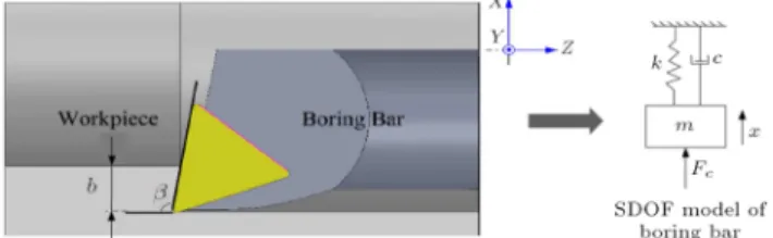
An internal turning operation using a single-point boring bar is illustrated in Figure 2. The bar is equipped with a cutting head for machining the inner surface of the workpiece with a depth of cut b and a feed rate f. During the entire operation, the tool and its support system move together, and the eective L=D of the boring bar remains constant.
The cutting force created by the tool and work-piece engagement excites the boring bar. It is assumed that the workpiece is solid with no vibrations and the boring bar is more exible than the workpiece. The deection of the boring bar under the inuence of the cutting force can be estimated by considering the torsional deection and the bending deection. The torsional deection of the tool tip is proportional to the length of the bar, while the bending deection is proportional to its third power. Hence, for the long boring bar, the torsional stiness is much higher than the bending stiness. Thus, the bending modes of vibrations in radial and the tangential directions are
Figure 2. A schematic of internal turning using a boring bar.
rstly taken into consideration. Since the tangential deection does not aect the dynamic chip thick-ness, radial deections represent the most inuential direction and the boring bar can be considered as a cantilever beam vibrating in the radial direction [20]. In addition, it was found that a single harmonic oscillator could be a reasonable approximation for the boring bar dynamics measured at the tool tip [21].
A boring bar can be modeled as a single-degree-of-freedom, mass-spring-damper system in x direction, as shown in Figure 2. In Figure 2, b is the depth of cut, is the approach angle of the insert, m, c, and k are the modal mass, damping coecient, and modal stiness of the boring bar, respectively, x is the tool tip displacement, and Fc is the cutting force in the x
direction.
It is assumed that the cutting force is expressed as a function of varying uncut chip areas, which is the product of the chip thickness and the depth of cut. Hence, the cutting force can be expressed as follows:
Fc = Kfb(h0+ hd); (1)
where Kf is the cutting force coecient; h0is the static
chip thickness.
By neglecting vibrations in the feed direction due to the high rigidity of the boring bar, the dynamic chip thickness (hd) can be dened by projecting the
obtained vibrations from the radial direction onto the chip ow direction, which is perpendicular to the cutting edge [1]:
hd(t) = [x(t T ) x(t)] cos ; (2)
where T is the spindle period.
The dynamic equation of motion can be written as follows:
mx(t) + c _x(t) + kx(t) = Fc
= Kfb (h0+ [x(t T ) x(t)] cos) : (3)
By substituting Lx(t T ) = e sTx(s), the resulting
transfer function between displacement x and reference chip loads in the Laplace domain becomes:
x(s) h0(s)=
KfbG(s)
1 + cos (1 e sT)KfbG(s): (4)
Figure 3. Closed-loop block diagram of the regenerative chatter in internal turning.
Thus, the cutting process for regenerative chatter becomes a closed-loop feedback diagram, as shown in Figure 3.
The characteristic equation of the closed-loop system is:
1 + cos (1 e sT)K
fbG(s) = 0: (5)
By assuming that the system oscillates with chat-ter frequency !cat the stability limit, the critical depth
of cut for stable machining is found to be: blim=2 cos K 1
fRe(G(j!c)): (6)
It is shown in [15] that by assuming a simple SDOF system that vibrates with the chatter frequency, !c, Eq. (4) can be written in the frequency domain by
substituting s = j!c:
( m!2
c+ j!cc + k)X(j!c) = Kfbh0 (1 e j!cT)
X(j!c) cos : (7)
By neglecting the eect of the feed, the dynamic equation of motion can be written as follows:
m!2
c+ j!c
c + Kfb cos
sin(!cT )
!c
+ (k + Kfb cos (1 cos(!cT )))
X(j!c)=0:
(8) A relationship between the damping coecient and the stability limit is found to be:
blim= csin(! !c
cT )Kfcos : (9)
Eq. (9) shows that the stability limit is directly pro-portional to the structural damping coecient, c. This implies that enhancing structural damping improves the stability limit. Therefore, the minimum value of depth of cut and the stable region of the machining process would increase. As an illustrative example for the described theory, the eect of increasing structural damping on a typical stability lobe diagram is shown in Figure 4.
Figure 4. Improvements in the stability lobe diagram due to increasing the damping of the tool structure.
3. Boring bar setup
3.1. Specication of components
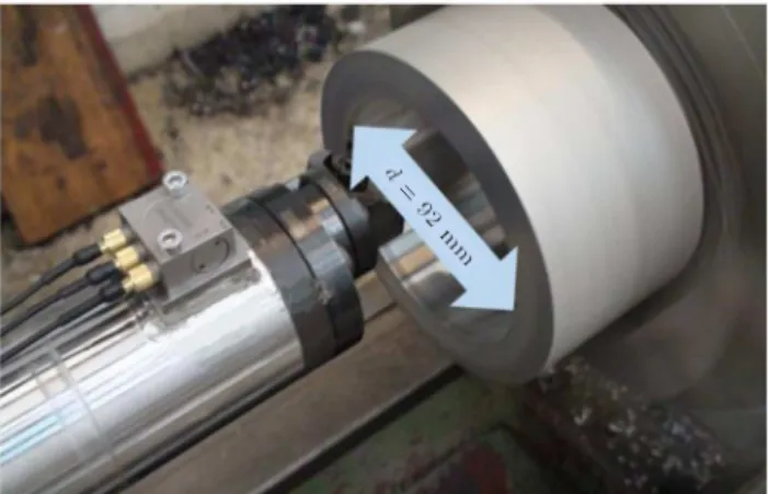
A specially designed long steel boring bar with a diameter of 60 mm and an overall length of 1100 mm with the eective cantilever length in the range of 160-600 mm (L=D = 4 10) was used to study the active vibration control algorithms. The boring bar was clamped to a designed split collar boring bar holder, and the setup was attached to the cross-slide of a two-axis lathe machine. A picture of the components assembled on the lathe is shown in Figure 5.
The lathe was a 5.5 kW, two-axis MST TN50BR
Figure 5. Boring bar assembly.
with a 250 mm three-jaw chuck. The specications of boring setup are presented in Table 1.
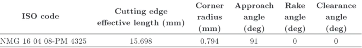
The tool was equipped with an exchangeable cutting tool from Sandvik Coromant with ISO TNMG coated carbide insert. The carbide inserts were used to machine Al 6063 cylinders. The geometrical properties of the cutting tool are presented in Table 2.
3.2. Preliminary experimental cutting tests Experimental cutting tests are important for the iden-tication of the dynamic behavior of the boring bar during machining processes. Preliminary tests were conducted on the above-mentioned setup for dierent L=Ds of the boring bar to investigate critical L=D and chatter signature for internal turning and to determine the amplitude and the main direction of cutting vibrations. The dynamics of the boring bar during these uncontrolled cutting tests was studied.
Table 1. Boring bar setup specications. Description
Boring bar material St44 steel with 50 micron hard chrome plating Overall length 1100 mm
Outer diameter 60 mm Inner diameter 35 mm
Clamping material GGG40 heat treated cast iron Clamping length 200 mm
Cutting head Manufactured by Sandvik Coromant Cutting head assembly 570-DTFNR T-Max®head for turning
with reduction adaptor 570-60 23-40
Table 2. The geometrical properties of the cutting tool.
ISO code Cutting edge
eective length (mm)
Corner radius (mm)
Approach angle (deg)
Rake angle (deg)
Clearance angle (deg)
Figure 6. Installed triaxial accelerometer on the boring bar.
Vibration signals during cutting tests were mea-sured by a triaxial integrated electronic piezoelectric (IEPE) accelerometer, Tenlee TL143A50 with a mea-surement range of 100 g, installed near the boring bar tip (see Figure 6). The charge signals produced by the accelerometer are conditioned and converted to voltage signals and recorded by the data acquisition system. The data acquisition system recorded data with a sampling rate of 50 kHz per channel.
Cutting tests were carried out using the boring bar on aluminum cylinders with 100 mm length, 120 mm outer diameter, and 90 mm inner diameter. The workpiece dimensions were selected in such a way as to be rigid compared to the tool. Specied cutting condition is provided in Table 3. The cutting con-ditions were selected based on insert manufacturer's recommendation for cutting speed and feed.
In cutting operations, surface quality is typically considered as the main indicator of chatter. By investigating the acceleration signals of the cutting tests recorded in stable and unstable conditions, it was observed that surface roughness had a direct relation with acceleration signal. Thus, stable or unstable cutting conditions can be identied by processing acceleration signals during the machining operation.
Results of cutting tests for each L=D of the boring bar were investigated to specify the critical L=D of the boring bar. By increasing L=D of the boring bar for given cutting parameters, process be-havior changes from a stable to unstable condition. Recorded acceleration signals can be used to identify the stable to unstable transition limits [21]. The eect of changes in L=D of the boring bar on acceleration
Figure 7. Acceleration signal in radial direction versus L=D: (a) Standard deviation of signals and (b) frequency domain (N = 500 rpm, b = 1, 2 mm, f = 0:16 mm/rev).
signal of vibration in the radial direction is shown in Figure 7.
In the stable cutting, the amplitude of acceler-ation signals was small, no dominant frequency was observed, and energy of signal was distributed over a wide frequency range. On the other hand, when the cutting was unstable, the amplitude of acceleration signals signicantly increased and a few dominant peaks appeared in the amplitude spectrum. It can be observed that the peak value of spectrum in unstable cutting was over two orders of magnitude larger than the dominant peak value in stable cutting, while, in other frequencies, the dierences were negligible.
Table 3. Specied cutting condition of experimental tests. L=D Cutting speed, v
(m/min)
Depth of cut, b (mm)
Feed, f (mm/rev)
The spectral pattern of unstable cutting vibration was usually dominated by the main chatter frequency and several of its harmonics. After a careful study of cutting tests results, it has been decided to mount the boring bar with L=D = 8 for active chatter control. 3.3. Structural dynamics of boring bar
The identication of structural dynamic behavior of a machine tool is very important for developing a vibra-tion damping system in order to suppress chatter. It provides eective information for selecting and locating an appropriate actuator and sensor.
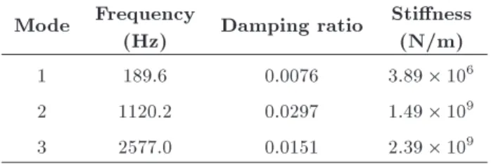
The experimental modal analysis was carried out for the boring bar using an impact hammer. The excitation force was applied by the impact hammer in the radial direction since it was the main direction of cutting vibrations, which is mostly responsible for the regenerative chatter. Impact tests were performed on L=D = 8 in order to specify the natural frequencies and mode shapes of the boring bar. Figure 8 presents experimental and curve-tted FRF of the boring bar for 0-3000 Hz in the radial direction. The estimated natural frequencies and the corresponding damping ratio and modal stiness are given in Table 4.
The comparison between the results of modal analysis and cutting tests shows that the rst bending vibration mode of the boring bar is the most important
Figure 8. Experimental and curve-tted FRFs for the rst three modes.
Table 4. Modal parameters. Mode Frequency
(Hz) Damping ratio
Stiness (N/m)
1 189.6 0.0076 3:89 106
2 1120.2 0.0297 1:49 109
3 2577.0 0.0151 2:39 109
mode during the machining process. Therefore, the actuator should be located where it can eectively control the rst bending vibration mode of the boring bar.
4. Active vibration control system
The closed-loop system should be designed to be robust and to improve the dynamic performance of the original system. The objective of the active vibration control system is to increase the damping of the resonant peaks on the response of the boring bar. Factors aecting the selection and placement of actuators and sensors can be mentioned as follows. In the rst step, it is important that actuators and sensors can be easily assembled to the machine tool structure while being able to withstand the harsh environment of machining. Additionally, it should be ensured that the placement of actuators and sensors results in a desirable system, which is capable of implementing dierent types of feedback control algorithms.
Mostly used actuator types for vibration control consist of: smart materials, electromagnetic, hydraulic, and pneumatic actuators. The hydraulic and pneu-matic actuators have great force and stroke capabilities, but exhibit insucient bandwidth for eective chatter control. Piezoelectric and magnetostrictive actuators have hysteresis, which should be modeled and com-pensated in the controller, therefore complicating the design of the linear controllers [22]. Electromagnetic actuators are inexpensive with adequate bandwidth and reasonable stroke and have a proven reliable technology. Although there is a nonlinear relation between the magnetic force and the command current for magnetic actuators, the VCA actuators can be designed to produce a linear relationship between the command signal and the output force [23].
Voice Coil Actuators (VCAs) are direct-drive, high-power-density devices with limited motion that deliver a force proportional to the current applied to its voice coil. These electromagnetic devices are used in dierent applications that require high acceleration and accuracy. The mechanism of a VCA is governed by the Lorentz Force Principle. They consist of a permanent magnet and a coil winding. When a current is applied to the coil, a force is generated [24].
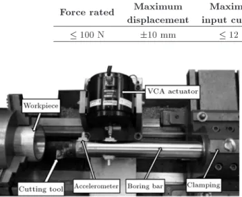
In this paper, a VCA actuator, Tenlee MS100, is placed in the direction normal to the machined surface in order to attenuate radial vibrations. The specication of the actuator is presented in Table 5. The actuator is bolted to a custom-designed movable support whose attachment point on the boring bar can be adjusted. The moveable support slides on the lathe guides with the boring bar and transfers reaction force to the lathe structure in a parallel path. The picture of components is shown in Figure 9.
Table 5. VCA actuator specications. Force rated Maximum
displacement
Maximum
input current Frequency range Power amplier
100 N 10 mm 12 A 0-4 kHz 500 watt
Figure 9. Active damping setup installed on the lathe.
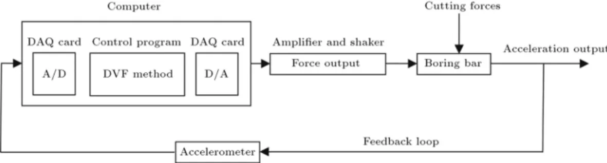
The experimental control system is comprised of a PC with an Advantech PCI-1710 HG Card and an Advantech PCI-1720 Card installed, the VCA actuator, a linear power amplier, an optical isolator, a piezo-electric accelerometer, and a signal conditioner. The control program was written in MATLAB/Simulink with Real-Time toolbox with a sampling rate of 20 kHz. High sampling rate guarantees that the desired fre-quency content of the signal (up to 200 Hz) would not be aliased, leading to the destabilization of the control system. The hardware architecture of active boring bar setup is illustrated in Figure 10.
A linear power amplier, Tenlee LA-500, with 4 kHz bandwidth is used to drive the VCA actuator. An IEPE accelerometer, Tenlee TL122A100, is selected to measure the structural vibrations and provides feed-back signal for the active control during cutting tests.
It is placed near the tip of the boring bar to provide an appropriate structural vibration signal required for active control performance. It is a special light-weight sensor; therefore, the eect of the accelerometer mass loading on the structural dynamics can be neglected. It has a measurement range of 50 g up to 10 kHz. A Tenlee multi-channel signal conditioner type 8204 converts the charge signals generated by the accelerom-eters into voltage signals, which can be recorded and evaluated. The actuator is located 200 mm from the boring bar tip. For ecient actuation, the location of the actuator and the accelerometer should be selected and possibly collocated. In a collocated conguration, the measurement and the actuation point are the same and, in active vibration control systems, it oers higher stability [25].
In this stage of our research, the above-mentioned commercial VCA is used, which is placed near the boring bar tip. After a comprehensive investigation of the boring bar/cutting operation interactions with the proposed controller and being able to achieve the main goal of increasing the stability boundary, we are planning to design an active control system using a VCA actuator and integrate it into the large-scale commercial internal turning boring bars.
5. System identication
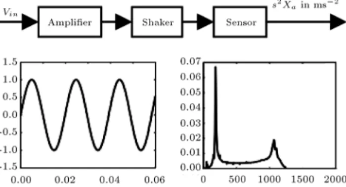
Development of active vibration control requires the identication of the dynamic response of the combined
Figure 11. Block diagram to determine actuator dynamics.
system including dynamics of all mechanical and elec-trical components. The frequency response technique is often used for the identication of a system. The open-loop frequency responses between the command voltage to the amplier and the resulting acceleration of boring bar were measured using a sine sweep, as shown in Figure 11. The structure was excited with the actuator, and the resulting vibrations were measured with the accelerometer. It is assumed that the boring bar has uncoupled dynamics in each direction. The bandwidth of excitation signal was swept in between 50 Hz-1250 Hz. The total measurement time was 10 s. The measurement was conducted with a sampling frequency of 20 kHz.
In this way, the FRF between the input voltage and the output acceleration was obtained. Figure 12 shows the measured and curve-tted open-loop FRF of the system. The root locus plot of the esti-mated transfer function of the system incorporating all mechanical and electrical components dynamics is shown in Figure 13. The estimated transfer function parameters are given in Table 6.
As shown, a linear second-order model can prop-erly describe the actuator dynamics [25]. In Table 6, the rst and third complex conjugate poles are natural frequencies of the boring bar. The second complex conjugate pole is the eect of the actuator in the open-loop transfer function. Therefore, the actuator model can be derived from the experimental measurements using a second-order model. Moreover, compared to modal analysis results, it is observed that the installation of the actuator on the boring bar slightly shifts natural frequencies and improves the structural
Figure 12. The measured and curve-tted open-loop FRFs of system.
Figure 13. The root locus plot of estimated transfer function of system.
damping of the boring bar for the rst two natural modes.
6. Controller design approach
There are examples of various active control algorithms in the literature used for rejecting the undesired
vibra-Table 6. Open-loop transfer function.
Pole Damping Frequency
(Hz)
Time constant (sec)
14:1 1160i 0.0121 184.6 7.09e-02
2530 3950i 0.54 746.4 3.95e-04
Figure 14. Block diagram of the disturbance rejection controller of active vibration control.
tions of dierent exible structures. Proper selection of control algorithm is dependent on a particular application. Direct Velocity Feedback (DVF) and Positive Position Feedback (PPF) are two examples of mostly used active vibration control strategies. PPF control is an eective active vibration control strategy that has been extensively used in vibration control of space structures. It has a good performance in con-trol systems with the non-collocated sensor/actuator conguration. DVF is based on the structural velocity feedback. Hence, DVF acts like viscous damping; it reduces response around resonance frequencies [26].
Munoa et al. [16] compared dierent control algo-rithms, including direct acceleration feedback control, DVF control, direct position feedback control, and delayed position feedback control for suppression of the regenerative chatter. The comparison demonstrated that the DVF control was the most eective strategy. Mancisidor et al. [27] proposed a coupled model for active vibration control of the milling process in time domain based on experimental data. The model was allowed to simulate dierent control strategies, control lters, and actuators. Cutting capability was doubled by implementing the DVF control strategy.
Mathematical formulation of the DVF control strategy considering dierent terms of the main regen-erative chatter equation based on orthogonal cutting for a single degree of freedom is as follows [16]:
mx(t) + c _x(t) + kx(t) = Kfb [h0 x(t) + x(t T )]
+ Fact; (10)
where m is the modal mass, c is linear viscous damping coecient, k is the modal stiness, Kf is the cutting
force coecient, b is the depth of cut, h0 is the static
chip thickness, and Fact is the control force:
Fact= g _x(t); (11)
where g is the feedback gain. Substituting the control force into Eq. (10) and simplifying notations, we get the following:
mx(t) + (c + g) _x(t) + kx(t) = Kfbh0 x(t)
+ x(t T ): (12)
It can be seen that the control force appears as viscous damping and increases the original damping ratio; thus, the critical depth of cut can be improved.
The block diagram of the developed active boring bar is given in Figure 14. The control program measures the tool acceleration by the accelerometer, predicts the vibration velocity through numerical inte-gration, and applies control voltage to the actuator via a linear amplier. The cutting force is considered as an unknown disturbance input to the boring bar. The output of the system is the acceleration of tool tip.
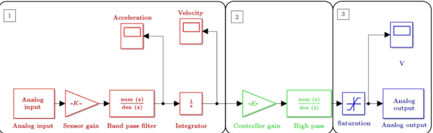
The simplied Simulink model created for the im-plementation of signal processing and feedback control is shown in Figure 15. It comprises three main groups of blocks: 1) acquisition and conditioning of accelerom-eter signal, 2) calculation of the velocity of the boring bar at the accelerometer point and generation of control voltage sent to the VCA actuator using DVF algorithm, and 3) application of the conditioned control voltage signal to the VCA actuator via the DAQ card. 7. Experimental results and discussion
The aim of active vibration control is to enhance the dynamic stiness of the boring bar in order to increase the chatter stability of the cutting process. Direct frequency response is an indicator of the dynamic stiness of the structure. Therefore, experimental modal analysis was carried out using impact hammer to measure FRFs between the input force (F ) and the tool tip acceleration in the radial direction. The performance of the active vibration control system was studied through the investigation of the eect of DVF control gain (g) in order to improve modal damping ratios by using the impact tests. The measured FRFs of the boring bar for L=D = 8 with various feedback gains are depicted in Figure 16.
It should be noted that g = 0 represents the boring bar without active damping, meaning that the control voltage is set to zero. In this case,
Figure 15. Simulink model created for active vibration feedback control.
Figure 16. Direct FRF for input force to tool tip acceleration of a boring bar with L=D = 8 for various control gains.
the VCA actuator acts only as an additional passive vibration absorber attached to the boring bar; hence, it slightly changes the natural frequencies and improves the modal damping. This case can be assumed as a reference for the non-controlled boring bar. Figure 16 shows that the main natural frequency of the boring bar, which is about 185 Hz, is eectively attenuated, and its dynamic stiness is substantially improved in the feedback control system. Thus, the DVF control algorithm can signicantly enhance the damping ratio of the boring bar.
As can be seen in Figure 16, by applying the DVF gain, at rst, the dominant peak of direct FRF decreases; consequently, modal damping considerably improves. The Low Authority Control (LAC), which is implemented for this part, consumes minimum energy [25]. Further increasing the DVF gain, say more than
1000, cannot signicantly reduce the value of the above-mentioned peak. The higher gain controller, which is called High Authority Control (HAC), requires great control eort. Eects of the DVF gain on the dominant natural frequency of the closed-loop control and its modal damping are compared with that of the open-loop system, as illustrated in Figure 17.
It can be observed that by increasing the DVF gain, the modal damping also improves. On the other hand, in the LAC region, the dominant natural frequency of closed loop slightly increases. However, in the HAC region, the DVF gain signicantly increases the dominant natural frequency; thus, a large amount of control eorts is required. Therefore, increasing the DVF gain without considering actuator cost may lead to the saturation of actuator. In addition, it can result in the instability of the dynamic system.
For the purpose of experimental study on the performance of the proposed active vibration con-trol system, a number of internal turning tests were conducted on aluminum cylinders. The objective of these tests is to gain a better insight into the overall performance system. The bar was overhung with L=D = 8. The radial depth of cut (b), the cutting speed (v), and the feed rate (f) were selected in the range of 0.05-2.5 (mm), 70-200 (m/min), and 0.16 (mm/rev), respectively. The cutting speed and the feed rate were selected based on the manufacturer's recommendation, and the depth of cuts ranging from roughing to nishing cutting was chosen.
For each cutting test, the accelerations of the active boring bar were measured. The cutting test was carried out in ascending order of the depth of cut for each cutting speed until the occurrence of chatter. The onset of chatter was determined by evaluating the surface nish and/or the amplitude spectrum of accelerometer signals.
In control-o cutting tests, the chatter frequency was close to the rst bending mode of the boring bar at 200 Hz, which has the lowest dynamic stiness.
Figure 17. Natural frequency and damping of the dominant mode of the closed-loop divided by the open-loop counterparts with respect to DVF gain.
Without active vibration control, the maximum depth of cut cannot reach more than 0.2 mm, which is way beyond the range of semi-rough internal turning.
In order to examine the eectiveness of DVF gains, the cutting tests with the same machining parameters were conducted with the active boring bar. The chatter suppression is a challenging task in practice; furthermore, the proper selection of the feedback gain for active vibration control is done. For machining operations, the performance of the closed-loop control system and its optimal behavior closely relates to chatter suppression. Therefore, assessing the eectiveness of control algorithms with modal experi-ments could obtain incorrect results. Large feedback gains necessitate large control eorts, though they do not denitely improve the dynamic behavior of the overall cutting process. Moreover, since the actuator
saturation can cause damage to the actuator, it should be avoided.
Although some authors investigated the perfor-mance of the DVF control algorithm in the cutting operation [28], no one evaluated the eect of the DVF gain on the improvement of the maximum stable depth of cut in machining operations.
Primarily, in order to conduct an experimental study on the eect of the DVF gain on chatter sup-pression, tentative cutting experiments with the xed cutting conditions and various DVF gains were carried out on the active boring bar. For these experiments, spindle speed (N), depth of cut (b), and feed rate (f) were set as 500 rpm, 0.5 mm, and 0.16 mm/rev, respectively. The acceleration (x) and control voltage signals (u) are recorded during tests. It should be noted that in order to protect the VCA actuator, RMS of control voltage should be less than 4 volts. The RMS values of the acceleration and the control output with respect to DVF gain are shown in Figure 18.
According to Figure 18(a), once the chatter is suppressed, RMS of acceleration signal does not change signicantly. However, in the case of g = 50, the controller cannot be eective; thus, RMS of accel-eration signal severely increases, which is a sign of chatter vibrations. In this illustrative case, although the controller has been eective and stable in hammer tests, the process becomes unstable in cutting, which means that, in active chatter suppression, the stability of the closed-loop control system is not enough, and the overall process stability should be taken into account.
On the other hand, according to Figure 18(b), for xed cutting conditions and various DVF gains while the control system and cutting process are both stable, RMS of control output signal has a direct relationship with the DVF gain. In these cases, a further increase in the DVF gain does not improve experimental outputs and it only continues to increase the controller output, which eventually leads to the saturation of actuator. Therefore, a compromise between the active damping and the control eort will be a better choice for selection the DVF gain.
In the developed experimental gain selection of DVF control, the controller gain is selected based on the experimental results of LAC region. In fact, when DVF gain is set to g = 1000, damping of the boring bar in impact tests is considerably improved, while the natural frequency of the closed-loop system varies about 10 percent.
The achieved stability charts of cutting tests with control o and control on cases with dierent DVF gains are illustrated in Figure 19.
The maximum depth of cut for the low DVF gains is relatively small due to the fact that active damping for chatter suppression is clearly inadequate. For the high DVF gains, the marginal depth of cut
Figure 18. The RMS values of the acceleration and the control output with respect to DVF gain (N = 500 rpm, b = 0:5 mm, and f = 0:16 mm/rev).
was constrained by actuator saturation, and a further increase in depth of cut would result in chatter. The actual cutting results show that the proposed optimal DVF gain demonstrates a superior performance in the enhancement of stable cutting boundaries. The maximum achievable depth of cut in cutting tests with active vibration control has substantially increased from 0.2 mm to 2.5 mm, which is an appropriate range of depth of cut for rough internal turning.
Furthermore, according to the cutting tests, ac-tive vibration control of the boring bar is not dependent on the spindle speed, and its eciency is preserved in higher spindle speeds. The eect of active vibration control on the amplitude spectrum of the acceleration signal in the radial direction for two critical cases (b = 0:25 mm in the control o test and b = 2:5 mm in the control on test) is shown in Figure 20.
According to Figure 20, the main chatter mode
Figure 19. Resulting stability chart for the control o and control on cutting tests with dierent DVF gains.
Figure 20. Amplitude spectrum of acceleration signal of control o test and control on test in the radial direction. (L=D = 8, N = 500 rpm, and f = 0:16 mm/rev).
is completely suppressed; further to this, since the natural bending modes are well damped with the active control strategy, the amplitude spectrum of acceler-ation signals with feedback control becomes similar to a random signal. Moreover, despite a substantial increase in the depth of cut in the control on test, the vibration signal shows slight variations in other frequencies. Surface quality of these two cases of the control on test and the control o test is shown Figure 21.
Although the surface nish notably improves for the control on case, it is not as good as that of stable cutting. Due to the large depth of cut, noises on the accelerometer will be amplied on the closed-loop con-troller. Nevertheless, it can be acceptable for roughing
Figure 21. Comparison of surface nish of internal turning for the control o and the control on tests.
operations. The results validate the eectiveness of the developed gain selection method, and the stability limit of machining can be substantially enhanced with the presented method.
8. Conclusion
This paper presents a vibration control system that investigates the performance of dierent DVF con-trol gains in the vibration suppression of the active boring bar. A detailed description of the setup and experimental control system was presented. Impact tests showed that the developed DVF controller could considerably improve the dynamic stiness of the boring bar. In addition, experimental cutting tests demonstrated that, in large depth of cuts, low DVF gains could not mitigate chatter and the whole process became unstable. On the other hand, high DVF gains maximized the control eort, which might saturate the actuator. The experimental gain selection method was developed to select a DVF gain that would be a trade-o between increasing damping and actuattrade-or etrade-orts. The eectiveness of the developed gain selection of the DVF controller was conrmed by the actual cutting tests. The optimal DVF gain considerably increased the stability limit of the cutting process, leading to an improvement in the machining productivity of the bor-ing bar. The presented active vibration control method proved to be independent of spindle speed; hence, desired machining parameters can be chosen without any diculty. Although the VCA actuator used in our setup has a limited force capability, the optimized DVF control shows great potential for improvement of the dynamic characteristics of long overhung boring bars. The proven DVF control algorithm can also reduce the surface roughness in various cutting conditions, which will be evaluated in future research work. The proposed setup can be used as an attachment for lathe machines in deep boring, and it considerably improves their performances. The extension of the designed setup can
also be implemented on the heavy duty boring machine without the need for changing in the machine.
References
1. Altintas, Y., Manufacturing Automation, 2nd Edition, Cambridge University Press, New York, U.S.A, pp. 125-131 (2012).
2. Venter, G.S., Silva, L.M., Carneiro, M.B., and Silva, M.M. \Passive and active strategies using embedded piezoelectric layers to improve the stability limit in turning/boring operations", International Journal of Advanced Manufacturing Technology, 89(9-12), pp. 2789-2801 (2017).
3. Munoa, J., Beudaert, X., Dombovari, Z., Altintas, Y., Budak, E., Brecher, C., and Stepan, G. \Chatter suppression techniques in metal cutting", CIRP Annals -Manufacturing Technology, 65, pp. 785-808 (2016).
4. Sims, N.D. \Vibration absorbers for chatter suppres-sion: A new analytical tuning methodology", Journal of Sound & Vibration, 301, pp. 592-607 (2007).
5. Tarng, Y.S., Kao, J.Y., and Lee, E.C. \Chatter sup-pression in turning operations with a tuned vibration absorber", Journal of Materials Processing Technol-ogy, 105, pp. 55-60 (2000).
6. Miguelez, M.H., Rubio, L., Loya, J.A., and Fernandez-Saez, J. \Improvement of chatter stability in boring operations with passive vibration absorbers", Interna-tional Journal of Mechanical Sciences, 52, pp. 1376-1384 (2010).
7. Yang, Y., Munoa, J., and Altintas, Y. \Optimization of multiple tuned mass dampers to suppress machine tool chatter", International Journal of Machine Tools and Manufacture, 50, pp. 834-842 (2010).
8. Liu, X., Liu, Q., Wu, S., Li, R., and Gao, H. \Anal-ysis of the vibration characteristics and adjustment method of boring bar with a variable stiness vibration absorber", The International Journal of Advanced Manufacturing Technology, 98, pp. 95-105 (2018).
9. Muhammad, B., Wan, M., Feng, J., and Zhang, W.H. \Dynamic damping of machining vibration: a review",
The International Journal of Advanced Manufacturing Technology, 89(9-12), pp. 2935-2952 (2017).
10. Tewani, S.G., Rouch, K.E., and Walcott, B.L. \A study of cutting process stability of a boring bar with active dynamic absorbent", International Journal of Machine Tools and Manufacture, 35, pp. 91-108 (1995).
11. Andren, L. and Hakansson, L., Active Vibration Con-trol of Boring Bar Vibration, Research Report No 2004:07, Blekinge, Sweden, pp. 5-24 (2004).
12. Matsubara, A., Maeda, M., and Yamaji, I. \Vibration suppression of boring bar by piezoelectric actuators and LR circuit", CIRP Annals - Manufacturing Tech-nology, 63(1), pp. 373-376 (2014).
13. Chen, F. \Active damping of machine tools with mag-netic actuators", Ph.D. Dissertation, The University of British Columbia, Vancouver, Canada (2014).
14. Pratt, J.R. and Nayfeh, A.H. \Chatter control and stability analysis of a cantilever boring bar under regenerative cutting conditions", Philosophical Trans-actions of the Royal Society A: Mathematical, Physical and Engineering Sciences, 359, pp. 759-792 (2001).
15. Ganguli, A., Deraemaeker, A., and Preumont, A. \Regenerative chatter reduction by active damping control", Journal of Sound and Vibration, 300, pp. 847-862 (2007).
16. Munoa, J., Mancisidor, I., Loix, N., Uriarte, L.G., Barcena, R., and Zatarain, M. \Chatter suppression in ram type travelling column milling machines using a biaxial inertial actuator", CIRP Annals- Manufac-turing Technology, 62, pp. 407-410 (2013).
17. Chen, F., Hanifzadegan, M., Altintas, Y., and Lu, X. \Active damping of boring bar vibration with a magnetic actuator", IEEE/ASME Transactions on Mechatronics, 20, pp. 2783-2794 (2015).
18. Hayati, S., Hajaliakbari, M., Rajabi, Y., and Rasaee, S. \Chatter reduction in slender boring bar via a tunable holder with variable mass and stiness", Pro-ceedings of the Institution of Mechanical Engineers, Part B: Journal of Engineering Manufacture, 232, pp. 2098-2108 (2018).
19. Abele, E., Haydn, M., and Grosch, T. \Adaptronic approach for modular long projecting boring tools", CIRP Annals - Manufacturing Technology, 65, pp. 393-396 (2016).
20. Moetakef-Imani, B. and Yussean, N.Z. \Dynamic simulation of boring process", International Journal of Machine Tools and Manufacture, 49, pp. 1096-1103 (2009).
21. Prosperi, F. \Manufacturing of high precision mechan-ical components", Ph.D. Dissertation, University of Udine, Italy (2014).
22. Park, G., Bement, M.T., Hartman, D.A., Smith, R.E., and Farrar, C.R. \The use of active materials for machining processes: A review", International Journal of Machine Tools and Manufacture, 47, pp. 2189-2206 (2007).
23. Chen, F., Lu, X., and Altintas, Y. \A novel mag-netic actuator design for active damping of machining tools", International Journal of Machine Tools and Manufacture, 85, pp. 58-69 (2014).
24. Lang, G.F. and Snyder, D. \Understanding the physics of electrodynamic shaker performance", Sound and vibration, 35, pp. 24-33 (2001).
25. Preumont, A., Vibration Control of Active Structures, An Introduction, 3rd Edition, Kluwer Academic Pub-lishers, Dordrecht, Netherlands (2011).
26. Shin, C., Hong, C., and Jeong, W.B. \Active vibra-tion control of beams using ltered-velocity feedback controllers with moment pair actuators", Journal of Sound and Vibration, 332, pp. 2910-2922 (2013).
27. Mancisidor, I., Munoa, J., Barcena, R., Beudaert, X., and Zatarain, M. \Coupled model for simulating active inertial actuators in milling processes", The Interna-tional Journal of Advanced Manufacturing Technology, 77, pp. 581-595 (2015).
28. Kleinwort, R., Schweizer, M., and Zaeh, M.F. \Com-parison of dierent control strategies for active damp-ing of heavy duty milldamp-ing operations", Procedia CIRP, 46, pp. 396-399 (2016).
Biographies
Pooria Naeemi Amini received BSc and MSc degrees in Mechanical Engineering from Ferdowsi University of Mashhad (FUM), Iran in 2006 and 2009, respectively. He is currently pursuing the PhD degree at the Depart-ment of Mechanical Engineering at Ferdowsi University of Mashhad. His research interests include identica-tion, vibration control, and machining dynamics. Behnam Moetakef-Imani is a Professor of Me-chanical Engineering at the Ferdowsi University of Mashhad (FUM), Iran. He received his PhD in Me-chanical/Manufacturing Engineering from McMaster University, Ont., Canada, MSc in Mechanical Engi-neering from Technical Faculty, Tehran University, and BSc in Mechanical Engineering from Sharif University of Technology, Tehran, Iran. His current research focuses on machining dynamics, numerical control, and CAD/CAM.