Lighting Control Console
Operations Manual
Version 2.0
Copyright © 2013 Electronic Theatre Controls, Inc. All Rights reserved. Product information and specifications subject to change. Part Number:4310M1210-2.00 Rev A
ETC®, Eos™,Eos Ti™, Gio®,Ion®, Element™, Emphasis®, Expression®, Insight™, Imagine™, Focus™, Express™, Unison®, Obsession® II, ETCNet2™, EDMX™, Revolution® and Sensor+®, are either registered trademarks or trademarks of Electronic Theatre Controls, Inc. in the United States and other countries.
T a b l e o f C o n t e n t s
Introduction . . . 1
Using this Manual. . . .2
Register Your Ion . . . .3
Help from ETC Technical Services . . . .3
Important Concepts . . . .4 Channel = Fixture . . . .4 Output . . . .4 Record Target . . . .4 Move Instruction . . . .4 Manual Data . . . .4 Syntax Structure . . . .4
Parameters and Parameter Categories . . . .5
Tracking vs. Cue Only . . . .5
Move Fade. . . .6
Block vs. Assert . . . .6
Live and Blind . . . .7
HTP vs. LTP . . . .7
Other Reference Materials . . . .8
Help System . . . .8
Online Eos Family (Eos Ti, Eos, Gio and Ion) User Forums . . . .8
C h a p t e r 1
System Overview . . . 9
System Components . . . .10
Console . . . .10
Remote Processor Unit (RPU). . . .10
Remote Video Interface (RVI) . . . .10
Radio Focus Remote (RFR) . . . .10
iRFR and aRFR . . . .10
Gateways. . . .11 Console Geography . . . .12 Terminology . . . .13 Littlites® . . . 14 Cleaning Ion. . . .14 Outputting DMX . . . .14 Console Capacities . . . .15 Output Parameters . . . .15 Channel Counts . . . .15
Cues and Cue Lists . . . .15
Record Targets . . . .15
C h a p t e r 2
System Basics . . . 17
Setting Up the Hardware . . . .18
Power . . . .19
Power Up the Console. . . .19
Power Down the Console . . . .19
Your First Interaction . . . .20
Single Monitor Configuration . . . .20
Dual Monitor Configuration . . . .21
The Central Information Area (CIA) . . . .22
Parameter Display . . . .22
Browser . . . .22
Collapse/Expand the CIA. . . .22
Lock the CIA . . . .23
Favorite CIA Display . . . .23
Locking the Facepanel. . . .23
Using the Browser . . . .24
Virtual Keyboard . . . .24
Fader Module. . . .25
Using Direct Selects . . . .25
Direct Selects in Flexi Mode . . . .26
Clear Functions . . . .27
Display Control and Navigation . . . .28
Opening and Closing Displays. . . .28
Selecting Displays . . . .29
Moving Displays. . . .29
Scrolling within a Display . . . .29
Expanding Displays . . . .30
Zooming Displays . . . .30
Graphical User Interface (GUI) Display Conventions . . . .31
Indicators in the Live/Blind Display . . . .31
[Data] Key . . . .35
[Time] Key . . . .35
[Label] Key. . . .35
Using Flexichannel . . . .36
Indicators in the Playback Status Display . . . .37
Using [Format] . . . .39
Encoders . . . .45
Encoder Navigation . . . .45
Locking the Encoders . . . .45
Encoders in Blind. . . .45
Flexi Encoders . . . .45
Moving Light Controls. . . .46
ML Controls . . . .46
Using Softkeys . . . .47
C h a p t e r 3
Managing Show Files . . . 49
Create a New Show File. . . .50
Open an Existing Show File . . . .50
Selective Partial Show Opening . . . .52
Merging Show Files . . . .54
Printing a Show File . . . .55
Saving the Current Show File. . . .57
Using Quick Save. . . .57
Using Save As . . . .57
Importing Show Files . . . .57
Exporting a Show File . . . .58
Deleting a File . . . .58
File Manager . . . .58
C h a p t e r 4
Patch. . . 59
About Patch . . . .60
Displays . . . .61
Flexichannel Views in Patch . . . .62
Labeling . . . .62
Patching Conventional Fixtures . . . .63
Patching By Channel . . . .63
Range Patching . . . .63
Patching By Address . . . .63
Using Output Address vs Port/Offset. . . .64
Replace . . . .64
Helpful Hints . . . .64
{Address} [n] [/] . . . .64
Dimmer Doubling . . . .65
Moving and Copying Channels . . . .65
Swapping Channels. . . .66
Unpatch a Channel . . . .66
Deleting Channels . . . .66
Using {Offset} in Patch. . . .67
Creating multi-part and compound channels . . . .67
Using the Scroller/Wheel Picker and Editor . . . .68
Using the Picker. . . .68
Using the Editor . . . .69
Calibrating a Scroller Using the Encoders . . . .72
Calibrating a Scroller Using the ML Display . . . .74
Patching Moving Lights, LEDs, and Accessories . . . .75
Display Pages in Patch . . . .76
{Patch} Display and Settings . . . .76
{Database} Display and Settings . . . .80
Using Device List . . . .82
Dimmer List for CEM+, CEM3, and FDX 2000 . . . .82
RDM Device List . . . .84
Patching Discovered Dimmers and RDM Devices . . . .86
Errors and Warnings . . . .86
Detaching Devices. . . .87
Clearing the Patch . . . .87
Reset Patch . . . .87
Fixture Creator . . . .88
Creating a New Fixture . . . .88
Copying a Fixture. . . .92
Merging Custom Fixtures into a New Show File . . . .92
Importing a Custom Fixture . . . .92
Update Library . . . .92 Snap Parameters. . . .93
C h a p t e r 5
Setup . . . 95
Opening Setup . . . .96 Show . . . .96 Desk. . . .103C h a p t e r 6
Basic Manual Control . . . 111
Selecting Channels . . . .112
Select Channels From the Keypad . . . .112
Selecting Channels from Faders . . . .112
Using Groups as a Channel Collector . . . .112
Offset . . . .113
Setting Intensity . . . .114
Level Wheel . . . .114
Manual Control of Non-intensity Parameters (NPs) . . . .115
Parameter Display . . . .115
Setting Parameters with the Keypad . . . .116
Adjusting Parameters Using + and - . . . .116
Setting Non-intensity Parameters with the Encoders . . . .116
Using the Color Picker . . . .121
Home . . . .123
Select Last . . . .123
Multiple Intensity Channels . . . .124
Lamp Controls . . . .125
Using +% and -% . . . .126
Lowlight Preset . . . .128
Temporary Highlight Level. . . .129
Highlight/Lowlight Rem Dim. . . .129
Sneak . . . .130 Flip . . . .131 Channel Check. . . .131 Address at Level. . . .131 Address Check . . . .131 Flash. . . .132
Flash On & Flash Off . . . .132
Using {Move To}. . . .132
C h a p t e r 7
Using Groups . . . 133
Recording Groups Live. . . .134
Ordered Channels . . . .134
Offset . . . .135
Editing and Updating Groups in Live . . . .135
Selecting Groups . . . .135
Deleting Groups. . . .135
Group List. . . .136
Open the Group List . . . .136
Ordered View and Numeric View. . . .136
Editing Groups from the Group List . . . .136
Using Groups as a Channel Collector . . . .137
C h a p t e r 8
Storing and Using Palettes . . . 139
About Palettes . . . .140 Palette Types . . . .140 Intensity Palettes . . . .140 Focus Palettes . . . .140 Color Palettes . . . .140 Beam Palettes . . . .140 Palette Options. . . .140 {By Type} . . . .140 {Absolute} . . . .140 {Locked}. . . .141
Storing Palettes Live . . . .142
Storing Palettes with [Record] . . . .142
Storing Palettes with [Record Only] . . . .143
Using Filters with Palettes . . . .144
Recalling Palettes. . . .145
Editing Palettes Live. . . .146
Update . . . .146
Editing Palettes in Blind . . . .147
Entering Blind Palette from Live . . . .147
Editing in Blind . . . .147
Editing Palettes in Spreadsheet View . . . .148
Editing Palettes in List View. . . .148
Deleting Palettes . . . .149
Removing Channels from a Palette . . . .149
Using By Type Palettes . . . .150
Storing a By Type Palette . . . .150
Editing By Type Palettes in Blind. . . .150
Updating By Type Palettes . . . .150
C h a p t e r 9
Storing and Using Presets . . . 151
Storing Presets Live . . . .152
Storing Presets Using [Record] . . . .152
Storing Presets using [Record Only] . . . .153
Preset Options . . . .153
Recalling Presets . . . .154
Editing Presets Live . . . .155
Rerecord . . . .155
Update . . . .155
Using the Preset List . . . .156
Opening the Preset List . . . .156
Editing Presets in Blind . . . .157
Editing in Table View . . . .157
Editing in Spreadsheet View . . . .158
Deleting Presets . . . .158
Removing Channels from a Preset . . . .158
C h a p t e r 1 0
Using Fan . . . 159
About Fan. . . .160
Fanning Parameter Data . . . .160
Fan From the Command Line . . . .160
Fanning References . . . .161
Fanning Timing and Delays . . . .161
C h a p t e r 1 1
Working with a Single Cue List . . . 163
Basic Cueing . . . .164
Cue Numbering . . . .164
Recording Cues in Live . . . .165
Using [Cue Only / Track] . . . .168
Timing. . . .169
Setting Cue Level Timing. . . .169
Non-intensity Parameter Category Timing. . . .170
Delay Time. . . .171
[Time][/] . . . .171
Discrete Channel or Parameter Timing . . . .172
Assigning Cue Attributes . . . .173
Clearing Cue Attributes . . . .175
Flags. . . .176 Block . . . .176 Assert. . . .177 AllFade. . . .177 Mark. . . .177 Preheat . . . .177
Using External Links . . . .178
Modifying Cues Live . . . .179
Using [At] [Enter] . . . .179
Using Record . . . .179
Using Record Only. . . .180
Record and Record Only [+] . . . .180
Move To. . . .180
[Update] . . . .181
Recording and Editing Cues from Blind . . . .186
From Summary or Table Views . . . .187
From the Cue Spreadsheet . . . .187
Using Encoders in Blind. . . .188
Deleting Cues. . . .189
In Track Mode . . . .189
In Cue Only Mode . . . .189
C h a p t e r 1 2
Using Mark . . . 191
AutoMark . . . .192
Conditions Triggering an AutoMark . . . .192
Allowing a Live Move . . . .192
AutoMark and Timing. . . .192
Referenced Marks . . . .193
Setting Referenced Mark Flags . . . .193
Applying Flags as Channels are Marked . . . .194
Reference Marks and Timing. . . .197
Mark Time . . . .197
C h a p t e r 1 3
Using Filters . . . 199
Record Filters . . . .200
Partial Filters . . . .201
Removing Filters . . . .201
C h a p t e r 1 4
Working with Multiple Cue Lists . . . 203
Recording to a New Cue List . . . .204
Using Record . . . .204
Using Record Only. . . .204
Using Assert . . . .204
Using AllFade . . . .206
Changing the Active Cue List . . . .206
Using [Go To Cue] with Multiple Cue Lists. . . .207
Using Go To Cue 0 . . . .207
Using Go To Cue Out . . . .207
Using the Cue List Index . . . .208
Open the Cue List Index . . . .208
C h a p t e r 1 5
Multipart Cues. . . 211
About Multipart Cues . . . .212
Record a Multipart Cue in Live . . . .212
Creating a New Multipart Cue in Live . . . .212
Setting Multipart Cue Attributes . . . .213
Using Update in Live . . . .213
Storing a Multipart Cue in Blind . . . .214
Changing a Single Part Cue to a Multipart Cue. . . .214
Changing a Multipart Cue to a Standard Cue . . . .214
Deleting a Part from a Multipart Cue . . . .214
C h a p t e r 1 6
Cue Playback . . . 215
Introduction to Playback . . . .216 Playback Controls . . . .216 Selected Cue . . . .217 Live / Blind . . . .217 Out-of-Sequence Cues. . . .218 Go To Cue . . . .218 Slider Module . . . .220 Assigning Faders . . . .220Changing Fader Pages . . . .220
Playback Fader Controls . . . .221
Go and Stop/Back . . . .221
Using Blackout. . . .221
[Go To Cue] [0] . . . .221
Using Assert (Playback Button) . . . .224
Using Timing Disable. . . .224
Using Freeze . . . .224
C h a p t e r 1 7
Advanced Manual Control. . . 227
Using [Copy To] . . . .228
Using [Recall From] . . . .229
Using {Make Null}. . . .230
In Live . . . .230
In Blind. . . .230
Using {Make Manual} . . . .231
Using {Make Absolute} . . . .231
Using {Query} . . . .232 Using [Capture] . . . .233 Using [Undo]. . . .234 Command History . . . .234
C h a p t e r 1 8
Using Park . . . 235
Using Park . . . .236 Park Display. . . .236Parked Values in Live . . . .236
Scaled Parked Values in Live . . . .237
Parked Addresses in Live . . . .237
Park Values from the Park Display . . . .238
C h a p t e r 1 9
Creating and Using Effects . . . 239
About Effects . . . .240
The Effect List . . . .240
Effects Editor . . . .241
Effect Status Display . . . .244
Step Effects . . . .245
Program a Step Effect . . . .246
Absolute Effects . . . .248
Program an Absolute Effect. . . .249
Multiple Intensity HTP Effects . . . .250
Relative Effects . . . .250
Focus Effects . . . .250
Color Effects . . . .251
Linear Effects. . . .251
Define a Pattern Shape . . . .252
Program a New Relative Effect . . . .252
Apply an Existing Effect . . . .253
Recording an Effect in a Cue. . . .253
Editing Effects Live . . . .253
Stop an Effect . . . .253
Deleting an Effect . . . .253
Configuring an Effect Submaster. . . .254
Recording an Effect to a Submaster . . . .254
Running an Effect from a Submaster. . . .254
Delaying Effects . . . .255
C h a p t e r 2 0
Storing and Using Submasters . . . 257
About Submasters . . . .258
Recording a Submaster . . . .258
Submaster Displays. . . .259
Additive, Inhibitive, or Effectsub. . . .259
Proportional vs. Intensity Master . . . .259
HTP vs. LTP . . . .260
Exclusive Submasters . . . .260
Priority . . . .260
Restore . . . .261
Submaster Background State . . . .261
Changing Fader Pages . . . .262
On Fader Wings. . . .262
On the Slider Module . . . .262
Loading Submasters . . . .263
On Fader Wings. . . .263
On the Slider Module . . . .263
Updating a Submaster . . . .264
Releasing Content From a Submaster . . . .264
Deleting a Submaster . . . .264
Using Bump Button Timing With Submasters . . . .265
Controlling Subfades Manually . . . .265
Submaster List . . . .266 Editing Submasters . . . .266
C h a p t e r 2 1
Using About . . . 267
About [About] . . . .268 [About] . . . .269 About System . . . .269 About Channel . . . .270 About Address . . . .272 About Cue . . . .275About IFCB Palettes . . . .275
About Presets . . . .275
About Groups. . . .275
About Curves . . . .276
About Effects . . . .276
Creating a Curve . . . .279 Editing Curves . . . .280 Applying a Curve . . . .281 To Channels In Patch . . . .281 To Cues . . . .281 To Scroller Fans . . . .281 Delete a Curve . . . .281
C h a p t e r 2 3
Storing and Using Snapshots . . . 283
About Snapshots . . . .284
Recording Snapshots . . . .284
Recalling Snapshots. . . .285
Editing Snapshots . . . .285
Deleting Snapshots . . . .285
C h a p t e r 2 4
Storing and Using Macros. . . 287
About Macros . . . .288
Store a Macro from Live . . . .288
Using the [Learn] key. . . .288
Macro Editor Display . . . .290
Create a New Macro from the Display. . . .292
Edit an Existing Macro . . . .293
Play a Macro . . . .294
Stop a Macro . . . .294
Delete a Macro . . . .294
C h a p t e r 2 5
Using Magic Sheets . . . 295
About Magic Sheets . . . .296
Magic Sheet Display. . . .297
Magic Sheet List . . . .298
Display Tools . . . .298
Navigating a Magic Sheet . . . .299
Creating and Editing Magic Sheets . . . .300
Quick Save . . . .300
Layout Tools . . . .301
Magic Sheet Object Library . . . .303
MS Object Properties. . . .307
Editing Objects on the Magic Sheet. . . .308
C h a p t e r 2 6
Virtual Media Server . . . 311
About Virtual Media Server . . . .312
Media Content . . . .312
Patching the Virtual Media Server and Layers . . . .314
Creating a Pixel Map . . . .315
Working with the Virtual Media Server. . . .317
Effect Layers . . . .322
Pixel Mapping in a Multi-Console System . . . .324
Steps for Configuring a Multi-Console System . . . .324
Synchronizing Media Archives. . . .325
C h a p t e r 2 7
Multiple Users . . . 327
About User ID. . . .328
Assigning User ID . . . .328
C h a p t e r 2 8
Using Partitioned Control . . . 329
About Partitioned Control . . . .330
How to Use Partitions . . . .330
Setting Up Partitioned Control . . . .330
Partition List . . . .330
Creating New Partitions . . . .331
Deleting Partitions . . . .331
Using Partitions . . . .332
Partitions in Playback . . . .332
Flexichannel in Partitioned Control . . . .332
A p p e n d i x A
Eos Configuration Utility . . . 333
Overview . . . 333
What the Utility Does . . . 333
Eos Configuration Utility Reference . . . 334
General Settings. . . 336
Network Settings . . . 340
Maintenance and Diagnostics . . . 346
Buttons . . . 351
Local I/O . . . 351
RFR . . . 352
Operations . . . 354
A p p e n d i x C
Multi-console and Synchronized Backup . 357
Overview . . . 357Multi-console setup . . . 358
Synchronized Backup. . . 361
Mirror Mode . . . 365
A p p e n d i x D
Using the RPU and RVI . . . 367
RPU Overview . . . 367
Remote Processor Unit (RPU) . . . 368
Start Up . . . 369
Software Configuration. . . 370
Basic Use Guidelines . . . 371
Net3 Services . . . .371
RVI3 and RVI Overview . . . 372
Remote Video Interface 3 (RVI3) . . . 372
Remote Video Interface (RVI) . . . 373
Basic Use Guidelines for RVI3 and RVI . . . 375
A p p e n d i x E
Remote Control. . . 377
Remotes Overview . . . 377
Phone Remote. . . .377
Radio Focus Remote (RFR) . . . .378
Console Section Mode . . . .379
Basic Use Guidelines . . . 381
RFR Operation Modes . . . 383
Technical Specifications. . . 387
iRFR. . . .388
aRFR . . . .388
A p p e n d i x F
Universal Fader Wings . . . 389
Overview . . . 389
1 x 20 Setup . . . 389
2 x 10 and 2 x 20 Setup . . . 389
Introduction
Welcome to the Ion Operations Manual. This manual is a comprehensive resource for users of the Ion control system.
This chapter contains the following sections:
• Using this Manual . . . .2
• Register Your Ion. . . .3
• Help from ETC Technical Services. . . .3
• Important Concepts. . . .4
• Other Reference Materials . . . .8 • Online Eos Family (Eos Ti, Eos, Gio and Ion) User Forums .8
N o t e :
For information on using show control with your system, see the Eos Family Show Control User Guide, which is available for download at www.etcconnect.com.Using this Manual
In order to be specific about where features and commands are found, the following naming and text conventions will be used:
• Facepanel buttons are indicated in bold [brackets]. For example, [LIVE] or [Enter]. Optional keys are indicated in <angle brackets>, for example, <Cue> or <Sub>. • Browser menus, menu items, and commands you must perform are indicated in bold
text. For example: In the File menu, click Open. Or: Press [Record] [Preset] [Enter]. • Alphanumeric keyboard buttons are indicated in all CAPS. For example, TAB or CTRL. • Keys which are intended to be pressed or held simultaneously are indicated with the
“and” symbol. For example, [Load] & [Timing Disable].
• Softkeys and clickable buttons in the Central Information Area (CIA) are indicated in bold {braces}. A note about <More SK> (more softkeys): this command is always indicated as optional, and is only indicated once in an instruction regardless of how many pages of softkeys exist. This is because there is no way to predict what softkey page you are on at any given time. Press <More Softkeys> until you find the required command.
• References to other parts of the manual are indicated in italics. When viewing this manual electronically, click on the reference to jump to that section of the manual.
Please email comments about this manual to: [email protected]
N o t e :
Notes are helpful hints and information that is supplemental to the main text.C A U T I O N :
A Caution statement indicates situations where there may be undefined or unwanted consequences of an action, potential for data loss or an equipment problem.W A R N I N G :
A Warning statement indicates situations where damage may occur, people may be harmed, or there are serious or dangerous consequences of an action.Register Your Ion
Registering your Ion system with ETC ensures that you will be notified of software and library updates, as well as any product advisories.
To register your console, you will need to enroll in “My ETC,” a personalized ETC Web site that provides a more direct path of communication between you and ETC.
Register now at http://www.etcconnect.com/product.registration.asp.
Help from ETC Technical Services
If you are having difficulties, your most convenient resources are the references given in this user manual. To search more widely, try the ETC Web site at www.etcconnect.com. If none of these resources is sufficient, contact ETC Technical Services directly at one of the offices identified below. Emergency service is available from all ETC offices outside of normal business hours.
When calling for assistance, please have the following information handy: • Console model and serial number (located on back panel) • Dimmer manufacturer and installation type
• Other components in your system (Unison®, other control devices, etc.)
Americas
United Kingdom
Electronic Theatre Controls Inc. Electronic Theatre Controls Ltd. Technical Services Department Technical Services Department 3031 Pleasant View Road 26-28 Victoria Industrial Estate Middleton, WI 53562 Victoria Road,
800-775-4382 (USA, toll-free) London W3 6UU England +1-608 831-4116 +44 (0)20 8896 1000
[email protected] [email protected]
Asia
Germany
Electronic Theatre Controls Asia, Ltd. Electronic Theatre Controls GmbH Technical Services Department Technical Services Department Room 1801, 18/F Ohmstrasse 3
Tower 1, Phase 1 Enterprise Square 83607 Holzkirchen, Germany 9 Sheung Yuet Road +49 (80 24) 47 00-0
Kowloon Bay, Kowloon, Hong Kong [email protected]
+852 2799 1220
Important Concepts
Before using Ion, you should read and familiarize yourself with the concepts defined below. You will find that understanding these terms and concepts will improve your efficiency with Ion.
Channel = Fixture
A fixture is defined as a group of related addresses that together control a device. An examples of a fixture would be an ETC Revolution. This moving light contains 31
parameters that together allow you to perform various functions such as pan and tilt. Each of these attributes is addressed by a different output.
Ion treats fixtures and channels as one and the same. Unlike former ETC consoles where a fixture occupied one channel for each parameter, Ion assigns each fixture a single channel number. Individual parameters are then associated with that channel as additional lines of channel information.
Output
Outputs are the method by which level changes to channels are conveyed to attached devices. These outputs are patched to channels. In its simplest form, an output is the data signal sent from the console to turn on a light or modify a fixture parameter.
Record Target
A record target is any data location that you can store data using a [Record] or [Record Only] command. Examples of record targets are cues, palettes, presets, and macros.
Move Instruction
A move instruction is any change to a parameter from its previous stored value. Any change to a channel’s intensity is a move instruction. Any change to a channel’s pan or tilt is a move instruction. Any change to a channel’s color mixing is a move instruction, and so on.
Manual Data
Manual data is any value set for a channel via the command line. Manual data will remain at its value until a move instruction is provided for it.
Syntax Structure
Most instructions can be entered into Ion through the command line. The Ion command line expects instructions to be entered in a specific structure, or syntax.
Generally speaking, the order of syntax can be described as: • What are you trying to affect? (Channel, group)
• What do you want it to do? (Change intensity, focus, pan and tilt) • What value do you want? (Intensity at full, Iris at 50)
Naturally other commands will be used in the course of programming your show, but most other functions are modifiers of these three basic steps: modifying the channel(s) you are are working with, determining what parameters of those channels you are impacting, and what value you want them to assume. When working with record targets, the syntax is similar.
Enter
Since the command line can receive multiple edits and instructions at once, it is necessary to let Ion know when you have completed your instruction in the command line. This is done with the [Enter] key.
There are some commands which are self-terminating, and therefore do not require [Enter]
to be pressed. Some (but not all) of these commands are:
• [Out] • [Shift] & [+] • [Shift] & [-]
• [Full] [Full]
• Actions from the direct selects
Parameters and Parameter Categories
Ion divides fixture parameters into four major parameter categories: Intensity, Focus, Color, and Beam. These are the parameters in each category:
• Intensity . . . Intensity • Focus . . . Pan and Tilt
• Color. . . All color parameters (such as color wheel, CMY, scrollers, and so on).
• Beam . . . Any parameter not covered in the other categories.
Tracking vs. Cue Only
Ion is, by default, a tracking console. This means two things. First, tracking relates to how cue lists are created. Once data is in a cue list, it will remain a part of that cue list, at its original setting, and track forward through subsequent cues, until a new instruction is provided or until it is removed from the cue list using filters or null commands.
Secondly, tracking relates to how changes to cue data are handled. Unless otherwise instructed by a Cue Only command, changes to a parameter in a cue will track forward through the cue list until a move instruction (or block command) is encountered.
It is possible to change the default setting of Ion to “Cue Only”. This prevents changes from tracking forward into subsequent cues, unless overridden with a track instruction.
Ion also has a [Cue Only/Track] button that allows you to record or update a cue as an exception to the default setting. Therefore, if the console is set to Tracking, the button acts as Cue Only. If console is set to Cue Only, it behaves as a Track button.
Move Fade
Move Fade is a lighting control philosophy which determines how cues are played back. Ion adheres to this philosophy.
In a Move Fade system, parameters do not change from their current setting until they are provided a move instruction in a cue or are given a new instruction manually.
For example, in cue 1, channel 1 has been given an intensity value of 50%. This value does not change until cue 20, where channel 1 is moved to 100%. Therefore, channel 1 has a tracked intensity value of 50% in cues 2-19. If the user applies a manual intensity value of 25% while sitting in cue 5 (for example), that channel will stay at 25% until Cue 20 is recalled - because 20 is the next cue in which channel 1 has a move instruction. The original intensity of 50% will not be reapplied in subsequent cues unless specifically called out by the cue or manually performed.
Cue List Ownership
Ion is capable of running multiple cue lists. In a multiple-cue-list console, cue list ownership is an important concept. Cue list ownership is determined by the cue from which a channel is currently receiving its value. In Live, a parameter is considered to be “owned” by a cue list when it is receiving its current value from that cue list.
When alternating between cue lists in sequential playback, an active cue list does not necessarily own a channel unless that list has provided the last move instruction for that channel. For example, assume a channel is owned by cue list 1 and is at a tracked value. If a cue from another cue list is executed and provides a move instruction for the channel in the new cue, the channel is now owned by the second cue list. It will not return to cue list 1 until that cue list provides a move instruction for the channel.
Assert may be used to override this default behavior, allowing a cue list’s control over a channel to resume, even when the channel’s data is tracked.
This rule is not followed when executing an out-of-sequence cue. An out-of-sequence cue is any cue that is recalled via “Go To Cue”, a Link instruction, or manually changing the pending cue. In general applications, the entire contents of the cue (both moves and tracks) will be asserted on an out-of-sequence cue.
Block vs. Assert
In previous ETC consoles, placing a block instruction on a channel was a way to treat a tracked value as a move instruction, both in editing and playback. In Ion, this behavior is now split up. Blocked channel data is an editing convention only, and it prohibits tracked instructions from modifying the associated data. Blocked data has no impact on playback; the channels will continue to play back as though they were tracks. Assert is used to force playback of a tracked/blocked value.
Live and Blind
Live and Blind are methods to view and edit data in your show files. When you press the
[Live] key, the screen will show you the live display. When you press [Blind], you will see the blind display. In either case, you may use the [Format] key to alter how the data is displayed (see Using [Format], page 39).
When in Live, the data displayed represents the data being sent from the console at that moment. In other words, the parameter data that is “live” on stage. When you edit data in live, those changes will become active and visible on stage as soon as the command line is terminated.
When in Blind, the data displayed represents data from the record target you choose to view (cues, presets, palettes, and so on). When you edit data in Blind, changes will not automatically appear on stage, since the data you are modifying is not live. This is true even if the record target you are modifying is active on stage. It is possible to play a cue in Live, then switch to Blind and edit that cue in blind without affecting levels on stage. Edits in Blind do not require a [Record] command to be stored. They are considered stored when the command line is terminated. Any display that is not the Live display is considered Blind, and the Blind LED will be illuminated. For example, if you open patch, the blue LED on [Blind]
will be lit to show that you are in a Blind display.
HTP vs. LTP
HTP (Highest-Takes-Precedence) and LTP (Latest-Takes-Precedence) are terms used to define the output of a channel parameter that is receiving data from multiple sources. In HTP, the highest level of all sources will be executed. In LTP, the most recent level received will be executed. Cue lists and submasters can operate as HTP or LTP for intensity parameters only. Non-intensity parameters (NPs) are always LTP. Submasters can operate as HTP or LTP for intensity. The default is HTP. Ion’s default cue list setting for intensity is LTP (see HTP/LTP, page 209). Ion’s default submaster setting for intensity is HTP.
HTP
HTP is only applicable to the intensity of a channel. HTP channels will output the level that is the highest of all inputs. HTP channels are also referred to as “pile-on”, because as control inputs are added (for example - you may bring up cues and multiple submasters that all have the same channel recorded at various levels), the system calculates which input has the highest level for that channel and outputs that level for the channel. As control inputs are removed (you pull some of the submasters down to zero), the console will adjust the channel level, if required, to the highest remaining level.
LTP
LTP is applicable to any parameter of any channel. LTP output is based on the most recent move instruction issued to the channel parameter. Any new values sent to the channel will supersede any previous values, regardless of the level supplied.
Ion determines the LTP value for a channel, which is overridden by any HTP input values that are higher than the LTP instruction. This is then finally modified by manual control.
Other Reference Materials
Help System
A keyhelp system is also contained within your system. To access help, press and hold [Help] and press any key to see:
• the name of the key
• a description of what the key enables you to do • syntax examples for using the key (if applicable)
Online Eos Family (Eos Ti, Eos, Gio and Ion) User Forums
You are encouraged to visit and participate in the ETC Eos Family (Eos Ti, Eos, Gio and Ion) User Forum, accessible from the ETC web site (www.etcconnect.com). This gives you access to an online community of Eos, Eos Ti, Gio, and Ion users where you can read about other users’ experiences, suggestions, and questions regarding the product as well as submit your own.
To register for the ETC Family (Eos Ti, Eos, Gio and Ion) User Forum:
Step 1: Go to ETC’s community web site (www.etcconnect.com/community). An introduction page to the online community will open.
Step 2: You may register for the forum using the “register” link in the introduction or by clicking the “join” link in the upper right corner of the page.
Step 3: Follow the registration instructions provided by the community page.
N o t e :
Keyhelp is included on most tangible action buttons on your Ion console. This includes most softkeys and clickable buttons as well as the traditional keys on the keypad.As with hard keys, the “press and hold [Help]” action can be also used with softkeys and clickable buttons.
C h a p t e r 1
System Overview
Inside this chapter you will find general descriptions of your Ion control console, how it fits into a network control system, and the various areas of user interface.
This chapter contains the following sections:
• System Components. . . .10 • Console Geography. . . .12 • Cleaning Ion. . . .14 • Outputting DMX . . . .14 • Console Capacities . . . .15
System Components
Console
Ion is designed from conception as a fully integrated controller for conventional lights and
multi-parameter devices (for example: moving lights, LEDs, color scrollers, gobo wheels). Attention to detail across all areas of the system design and architecture allows you the utmost flexibility and customization of use.
Ion allows designers and programmers to develop a mutual vocabulary for control. This implementation of simple and uniform syntax for control provides a solid foundation for both experienced and inexperienced users.
Remote Processor Unit (RPU)
The RPU can be used as the primary, backup processor for the system, a client, or for primary playback in installations that do not require a facepanel after initial programming is completed. For more information, see the appendix Remote Processor Unit (RPU), page 383.
Remote Video Interface (RVI)
The remote video interface allows remote interaction with the lighting control system. This can be for display purposes only. Additionally, with a mouse and alphanumeric keyboard attached, the RVI can be used as a remote programming station. The RVI provides supports for a maximum of two DVI or SVGA monitors, 1280x1024 minimum resolution.
For more information, see the appendix Remote Video Interface (RVI), page 379.
Radio Focus Remote (RFR)
The RFR provides wireless control of key front panel functions.The base station for the RFR can be networked into the system, or can connect to a console or remote device using the USB interface. For more information, see the appendix Remote Control, page 377.
iRFR and aRFR
The iRFR and aRFR provide wireless control of key front panel functions.See “iRFR” on page 388.See “aRFR” on page 388.
Gateways
Ion is part of a fully networked system capable of direct output of both ETCNet2 and Net3. Gateways can be configured to listen to either ETCNet2 or Net3 and provide interface to devices in the lighting system that do not accept network communication directly. Gateways are provided for DMX/RDM output, show control input and output and analog input and output.
• Net3 to DMX/RDM gateways are provided with a maximum of four outputs, which can be male, female, or terminal strip.
• Show Control Gateway supports MIDI In/Thru and Out and SMPTE In.
• I/O Gateway supports 24 analog inputs, 16 SPDT contact closure outputs, and RS-232 serial protocol.
Console Geography
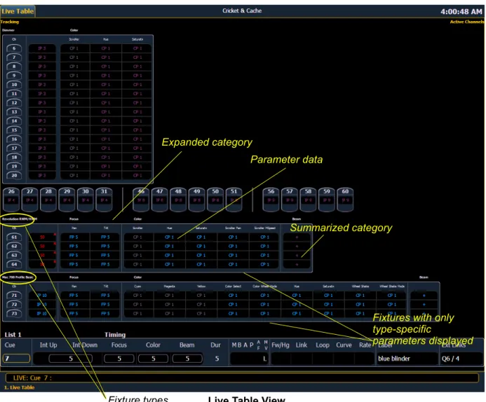
Below is a diagram of the Ion console with references made to specific areas of use. The terms and names for each area and interface are used throughout this manual.
Parameter category/ encoder page buttons Power button USB port Level wheel Navigation keys Paged encoders Control keypad Playback controls LCD screen Blackout and Grandmaster Softkeys
VGA port DVI video ports
IEC receptacle MIDI Out and In
Hard power switch Ethernet
port DMX ports 1 and 2 USB ports Remote trigger port Phone Remote Port Current Ion Rear panel Audio Ports (not currently supported)
IEC receptacle Ethernet MIDI Out and In port Remote trigger port Phone Remote Port Original Ion Rear panel
Terminology
Power Button
The power button on the front of the console is used to power up or power down. A separate power switch, located in the rear panel, can be used to disconnect power from the console’s internal components.
USB Ports
One USB port is provided on the front of the console to connect any USB storage device. An additional USB ports on the rear panel can be used to connect peripherals such as an alphanumeric keyboard, pointing device, or touchscreen control for external monitors.
.
Encoders
Encoders and the LCD (see below) for control of non-intensity parameters are provided at the top center of the console. The four encoders are pageable controls, which are populated on the LCD with the parameters used in your show.
LCD
This display accompanies the CIA as an additional user interface. This LCD offers you softkeys, encoder information, and an additional view of the command line.
Load
The load button is located above the fader pair at the bottom of the LCD and is used to load the specified cue.
Control Keypad
The control keypad area is divided into three general sections including record targets, numeric keypad and modifiers, and special function controls.
Level Wheel
Adjusts intensity for selected channels. It also provides scrolling and zoom functions in various modes.
Navigation Keypad
Used for quick access to the live and blind displays, format, paging, and navigation within displays.
Parameter Category/ Encoder Page Buttons
Parameter buttons are used to select parameter categories and change encoder pages. To post a parameter category to the command line, use [Shift] & [Encoder Page Button].
IEEE Ethernet 802.3 Ethernet Port
Ethernet port for connection to a network switch, network gateways, and accessory devices.
W A R N I N G :
Before servicing Ion, you must switch off the power on the rear panel and disconnect the power cord completely.Littlites
®
You may connect a Littlite to the side of your Ion console.
Dimming Littlites
Attached desk lamps can be dimmed either with the desk lamp control knob on the side of the console, or from the software.
Desk lamp controls are found in Setup>Desk>Brightness Settings. The {Desk Lamp} slider has a range of 0% (dimmest) to 100% (brightest). The default setting is 0%. The console will set the desk lamp to this setting on startup of the application. See “{Brightness Settings}” on page 108.
The desk lamps can also be controlled by holding down [Displays] and rolling the level wheel.
Cleaning Ion
Should the exterior or LCD of your Ion require cleaning, you may gently wipe them with a dampened (not dripping), non-abrasive paper towel or soft cloth.
If this does not clean the console sufficiently, you may apply some window cleaner (containing ammonia is fine) to the cloth and repeat the process until clean.
Outputting DMX
In order to output levels from Ion, you can either use the DMX ports on the back of the console, or to output over a network, you may connect a Net3 gateway or Net2 node. If your devices receive Net3 or ETCNet2 directly, no gateway or node is required.
Ion has two DMX ports. To output, connect one 5 pin XLR cable per port. The first port will default to outputting the first universe of DMX, addresses 1-512, and the second port to the second universe, outputting addresses 513-1024. See Local DMX Outputs, page 351 for information on reconfiguring the DMX ports.
Nodes and gateways will function with Ion out of the box without previous configuration. However if custom configuration is required, you will need to use either NCE (Network Configuration Editor) or GCE (Gateway Configuration Editor). GCE is installed on Ion by default and can be accessed in
ECU>Settings>Maintenance>Gateway Configuration Editor (GCE). NCE can be installed on the console or a Windows® PC for configuration.
For more information on Net3 gateways or Net2 nodes, see the product literature that accompanied the hardware or download it from our website at www.etcconnect.com.
Littlite XLR 3-Pin Female Connector
1 2
Console Capacities
Output Parameters
• 1,024 outputs (DMX channels) -or-• 1,536 outputs (DMX channels) -or-• 2,048 outputs (DMX channels) -or-• 3,072 outputs (DMX channels)Channel Counts
• 10,000 channels (any number from 1 to 99,999)
Cues and Cue Lists
• Up to 999 cue lists • Up to 10,000 cues
Record Targets
• 1,000 Groups
• 1,000 x 4 Palettes (Intensity, Focus, Color and Beam) • 1,000 Presets
• 1,000 Effects • 1,000 Macros
Faders
• 1 dedicated Master Playback, with Go and Stop/Back
• a maximum of 200 configurable playbacks, with Go and Stop/Back • a maximum of 300 configurable submasters, with Bump and Assert/Select
C h a p t e r 2
System Basics
This chapter explains the base level procedures for setting up, navigating, and understanding how to operate Ion.
This chapter contains the following sections:
• Setting Up the Hardware. . . .18 • Power . . . .19 • Your First Interaction. . . .20 • The Central Information Area (CIA) . . . .22 • Using the Browser. . . .24 • Display Control and Navigation . . . .28 • Graphical User Interface (GUI) Display Conventions. . . .31 • Using [Format]. . . .39 • Using Flexichannel . . . .36 • Encoders . . . .45 • Moving Light Controls. . . .46 • Using Softkeys. . . .47
Setting Up the Hardware
Follow these steps to prepare your Ion for use.
Step 1: Place your console on a firm, level surface. Be sure to leave space for access to the rear of the console. You will need to connect several items to the ports on the back. Step 2: Connect any monitors to the proper ports on the back of the console.
Step 3: Connect the keyboard and mouse. Attach to the appropriate connector on the back of the console.
Step 4: If you will be connecting to an Eos Family network, connect the appropriate Ethernet (CAT 5 or better) cable to the Ethernet port on the back of the console.
Step 5: If you plan on using the DMX ports on the back of Ion to control your lighting system, attach the appropriate DMX connector and cable to the desired port. These ports default to output DMX universes one and two. Configuration is required to use any other universe. For more information, see Local DMX Outputs, page 351 in the ECU appendix.
Step 6: Attach the appropriate IEC power cable for your location to the IEC connector on the back of the console, just above the power switch.
Your console hardware is now ready to be powered up.
Power
Power Up the Console
Step 1: Attach the appropriate power cable to the IEC connector on the rear of the console. Step 2: Press the I/O switch (I is “on”) next to the IEC connector on the rear of the console to
turn power on. This will provide power to all internal electronics.
Step 3: Press the power button, located in the top left corner of the console, above the USB port. The button LED will illuminate blue to indicate the console is running. The console will boot up into the Ion environment. The Ion system is now ready for use.
Power Down the Console
Step 1: After saving your show (see below), in the browser menu select Power Off Device. A dialogue box opens asking you to confirm.
Step 2: Confirm this command by clicking {OK} in the dialog box. The console will power down.
-Or-Step 1: Press the power button, located on the face panel. A dialogue box opens asking you to confirm.
Step 2: Confirm this command by pressing {OK} in the dialog box or by pressing the power button again. The console will power down.
N o t e :
You need to wait about 30 seconds between steps 2 and 3.N o t e :
In the future, you may go straight to the welcome screen by adjusting a setting in the ECU. See Open in Shell, page 337 in the ECU appendix.N o t e :
Ion is a persistent storage console. Therefore if you shut down your system without saving the show file, you will return to the same place in your show when you reboot.N o t e :
The console will display an improper shutdown message on the next power up if the console was not powered down from the browser menu or welcome screen.Your First Interaction
When you first start up Ion, you will immediately enter the Ion software environment.
Since Ion can be set up with one or two monitors, what you will first see depends partly upon the number of monitors you are using.
Single Monitor Configuration
When using a single monitor, the top half of the initial display screen becomes the primary viewing area for displayed information. Ion will first open with the live table display on the top (primary) half of the screen and the CIA on the bottom half of the screen.
When the CIA is open, one line of the playback status display is visible above the double arrows. You can view more of the playback status display by collapsing the CIA (see Collapse/Expand the CIA, page 22).
Initial View - Primary/CIA Primary screen - live display CIA Playback Status Display Command line Tabs
Dual Monitor Configuration
When two monitors are used, one monitor will default to showing the CIA, and the other will default to having the live display and the playback status display open on tabs.
For additional information on displays, see Display Control and Navigation, page 28.
Please see Monitor Arrangement, page 338 for more information on configuring Ion for a dual monitor configuration.
The Central Information Area (CIA)
The Central Information Area (CIA) is displayed on the lower portion of the screen. By default, the CIA consists of two primary areas: the parameter display and the browser.
Parameter Display
This display shows the parameters available for patched channels. It is also where you can select which parameters to view in live or blind, or select parameters for command line control. The parameter display will dynamically change depending on the channel (fixture) selected and its applicable parameters.
Browser
The browser is the interface for numerous functions including saving a show, opening a show, changing settings, viewing record target lists, opening displays and many other functions.
Collapse/Expand the CIA
It is possible to collapse the CIA from view. To do this, you can click the double arrow icon centered above the CIA. The CIA will collapse from view, exposing a larger viewing area of whatever display is visible above the CIA. The double arrows will move to the bottom of the screen.
To expand the CIA into view again, click the double arrow at the bottom of the screen. The CIA will reopen.
Parameter category button labels
Browser Parameter display
Double
arrows CIA lock Favorite star
Lock the CIA
You can lock the CIA in place to prevent it from being collapsed.
To lock the CIA, click on the lock above the browser. The double arrow above the CIA will disappear and the lock will “lock”.
To unlock the CIA, click the sunken lock again and the double arrows will reappear.
Favorite CIA Display
You can select a favorite default display for the CIA that will
show when [Displays] is pressed. The standard default display for the CIA is the Browser. The favorite display will show a gold star icon at the top of the CIA by the double arrows & lock. Displays that can be selected as a favorite, but are currently not, will show a grey star at the top of the CIA. Click on the grey star to make that display your favorite. That display will now be the new default display for the CIA. Displays that show up in the CIA but can not be the default display will not show the star icon.
The following displays can be set as the favorite CIA default: • About • Browser (default) • Color Picker • Direct Selects • Virtual Sliders • Virtual Keypad • ML Controls
• Encoder Information Screen • Effects Status
Locking the Facepanel
It is possible to lock out the facepanel, which prevents any actions from the command line or CIA. To lock out the facepanel, press [Shift] & [Escape]. To unlock the facepanel, press [Shift] & [Escape] again.
Using the Browser
To use the browser, you must first draw focus to it by clicking anywhere in the browser area of the CIA or by pressing the [Displays] key. If the browser is not visible, double pressing
[Displays]>Browser will always bring up the browser.
When focus is on the browser, the window border highlights in gold. The scroll lock LED illuminates red and the paging keys will now control selection in the browser.
• Use the page arrow keys to move the selection bar up and down the list. You can also use the level wheel to scroll through the list.
• When the bar highlights the desired menu, press [Page
] to open the menu. • Continue pressing [Page
] to open submenus.• Scroll to the item you wish to open using [Page
] or [Page
] and then press [Select]. You may also click the item you wish to open and then press [Select]. You can also use the level wheel to scroll in the browser.• If you wish to close a submenu scroll to that item and press [Page
]. • To draw focus to the CIA press the [Displays] key.• Additional presses of [Displays] will minimize or restore the CIA.
Virtual Keyboard
It is possible to open a virtual keyboard in the CIA which mimics the hard keys found on the actual Eos keypad. The keypad will not match the facepanel on Ion. This virtual keyboard is accessible from the browser.
To open the Virtual Keyboard on a monitor:
Step 1: Go to Browser>Virtual Controls>Virtual Keyboard. A window will open in the CIA displaying your monitor placement options for the keyboard.
Step 2: Click the placement option in which you want the keyboard to appear.
To close the Virtual Keyboard on a monitor:
Step 1: Go to Browser>Virtual Controls>Close Module. The placement screen will appear again in the CIA.
N o t e :
The [Select] key can be used to confirm a choice in the browser. Menu arrowsOpened menu Sub menus
Scroll bar Selection bar
Fader Module
If you prefer to have faders available to you, the monitors can be populated with virtual faders, called fader modules.
To open the fader module on a monitor:
Step 1: Go to Browser>Virtual Controls>Fader Module. A window will open in the CIA displaying your monitor placement options for the module.
Step 2: Click the placement option in the CIA in which you want the module to appear.
To close the fader module on a monitor:
Step 1: Go to Browser>Virtual Controls>Close Module. The placement screen will appear again in the CIA.
Step 2: Click the placement of the module you wish to close. The module will be removed.
Using Direct Selects
Direct selects allow access to a number of controls, including a channel select display. If there are more items than can be viewed at once, you may view subsequent pages by using the page buttons ({Page
}, {Page
}) by the direct selects.Selecting Channels with Direct Selects
Channel direct selects are highlighted when selected. Channel selection is generally an additive process, if channels 1-5 are selected, pressing {Channel 6} adds channel 6 to the selection, leaving channels 1-5 also selected. Pressing {Channel 6} again will deselect the channel. If you have labeled channels in patch, those labels will be displayed above the channel number when viewing channels in the direct selects.
It is possible to double hit a channel button. This selects that channel and deselects any previously selected channels.
• {Channel 1} - adds channel 1 to currently selected channels, if not currently selected. • {Channel 1} {Channel 10} - adds channels 1 and 10 to currently selected channels. • {Channel 1} {Channel 1} - selects channel 1, deselects all other channels.
• {Page
} - pages direct selects down by one page. • {Page
} - pages direct selects up by one page.Direct Selects
Ion gives you the option of opening direct select modules on the monitors.
To open the direct selects on a monitor:
Step 1: Go to Browser>Virtual Controls>5 x 10 Direct Select Module. A window will open in the CIA displaying your monitor placement options for the module.
Step 2: Click the placement option in which you want the module to appear.
To close the direct selects on a monitor:
Step 1: Go to Browser>Virtual Controls>Close Module. The placement screen will appear again in the CIA.
Step 2: Click the placement of the module you wish to close. The module will be removed. For information on populating direct selects see Organizing the Direct Selects.
Organizing the Direct Selects
You have considerable flexibility in how you organize the direct selects. They may be arranged to display one of several different types of data.
To choose which information to view:
Step 1: Click the {Select} button for any block of direct selects. You will be offered the following choices to view: Channels, Groups, Intensity Palettes, Focus Palettes, Color Palettes, Beam Palettes, Presets, Macros, Effects, and Snapshot.
Step 2: Click the button for the data you wish to view and the associated direct selects will populate with any recorded information of that type. If there is no recorded information of that type the block of buttons will remain empty but will populate with data of that type as associated record targets are stored.
Step 3: You may also click {Select} again, without choosing any option, to return to the previous state.
You can increase/decrease the size of any set of direct selects by pressing the {20/50} button, which will change the display between one set of 50 buttons and two sets of 20 buttons. Or you may press the {100} button to expand to a full set of 100 buttons. Press {100} again to switch back to the previous view.
You may also press the {Expand} button (located beneath the {Select} button) to expand a set of direct selects to full screen. Press {Expand} again to return the set to its previous size and mapping. Century and Millennium buttons will display when direct selects are in expand mode. When the direct selects are opened on a tab, two sets of direct selects will be displayed.
Direct Selects in Flexi Mode
Direct selects can be placed into a flexi mode, which will remove empty tiles. When {Select} is pressed, the {Show Flexi} button will display.
.
N o t e :
A single empty direct select tile may remain if the adjacent direct select tiles are not sequential. This is to allow an easy way to insert a new direct select between the existing ones.On
Off
Clear Functions
You can access the various clear options from the browser by selecting {Clear} from the main browser menu. The clear functions window will open in the CIA.
From this menu you can select one of the available clear options by clicking on the desired button in the CIA. Ion will ask you for a confirmation before performing the selected clear. For {Clear Targets}, Ion will allow you to choose which record targets you want to clear.
From the {Clear Targets} screen you can select which record targets you wish to clear. The buttons at the center of the CIA represent all of the record targets that you can choose to clear. By default all components are selected (gray) and will be cleared. To withhold any targets from being cleared, simply deselect them in the CIA by clicking the respective button.
To reselect all targets, click the {Reset} button and all buttons will return to gray (selected). To stop the process, click the {Cancel} button.
When you have selected or deselected all of the record targets you require, click {OK}.
After clearing, the CIA will return to the browser. If you want to perform additional clear functions, you must select {Clear} from the browser again.
To exit the clear functions screen without clearing, press the [Displays] key at any time or select a clear button and then select {Cancel} from the confirmation screen.
Reset System vs Clear Show
Using {Reset System} will open a new show file and reset the Setup options to their defaults. Using
{Clear Show} will only open a new show file.
Reset Patch vs Clear Patch
Using {Reset Patch} will clear your patch and set it to a 1-to-1 patch. Using {Clear Patch} will only clear out the patch.
Display Control and Navigation
Opening and Closing Displays
The live/ blind display will always open as tab 1. The playback status display will always open as tab 2. Neither of these displays can be closed.
Other displays are numbered as they are opened. Tab numbering is useful for navigating to views. Displays can be opened and closed in different ways, depending on the display. Many displays are accessible from the browser, while other displays are accessible from the LCD softkeys. The blind displays of record targets (also called “lists”) can be quickly accessed by double pressing the record target button (for example, [Preset] [Preset] opens the preset list).
From the browser
Open and navigate the browser as described in Using the Browser, page 24. When you open a new display (such as the cue list index, group list, or patch) and it is posted in a tab view, it will open on monitor 2. If the display does not open as a tab view (such as “setup” or the browser) it will open in the CIA.
Again, any time you wish to return to the browser, simply press [Displays] and then {Browser} and it will be made available.
From the hardkeys
You can open list views of any record target by double-pressing the key for the desired record target.
From the LCD softkeys
To open any displays accessible from the softkeys, press [Displays]. The softkeys will repaint to display: • Effect Status • Color Picker • Patch • Setup • Browser • Magic Sheet • Command History • Curves • Pixel Maps • Show Control • Mirror
Any of these softkeys will open the associated display with a single press.
Closing Displays
To close any tab display, select the display by using the [Tab] key or other means of navigation. When the desired display is active, press [Escape] to close it.
To close a display in the CIA, press the [Display] key and the browser will reappear.
To close all displays except for the live/blind display and the playback status display (tabs 1 and 2), press [Shift] & [Tab].
Selecting Displays
When a display is selected, the screen is highlighted in a gold border and the display name (such as “1. Live Channel”) will be in gold as well. When a display is not selected, there is no border and the tab name is gray.
If a display is already open, it can be selected in the following ways:
• Press [Tab] to change focus from the currently selected tab to the tab immediately to the right. If no tabs are to the right, the selection moves to the first tab on the left of all available monitors. • Press [Tab] & [n], where “n” represents the tab number of the desired tab.
• Press [Live] or [Blind] to automatically bring live/blind into focus. If there are multiple instances of live/blind, pressing [Shift] + [Live] / [Blind] brings the next live/blind tab into focus.
• Double press a record target button (such as [Preset] or [Submaster]) to either open the associated display or select it if it is already open.
Moving Displays
To move the active display from one monitor to another, press and hold the [Tab] key and use the page arrow keys to move the display in the direction of the desired screen. One press of the left or right page keys will move the display to the next screen in that direction. To move it back, press the opposite arrow key.
Scrolling within a Display
By default the page keys will advance/retreat a display by one page per press. However, to scroll through displays you may press the [Scroll Lock] key on the keypad. The LED on the button illuminates red when in scroll lock mode.
Scroll lock is a toggle state. When scroll lock is first pressed:
• [Page
] - scrolls table, spreadsheet and channel views down, • [Page
] - scrolls table, spreadsheet and channel views up, • [Page
] - scrolls table and spreadsheet views right, • [Page
] - scrolls table and spreadsheet views left.Expanding Displays
[Expand] allows a tab to be viewed across multiple external monitors.
To expand a display to an adjacent monitor, press [Expand] & [Page
] if in table viewsor[Expand] & [Page
] if in either view.To collapse an expanded view, press [Expand] & [Page
] if in table views or [Expand] & [Page
] if in summary views.Zooming Displays
You may zoom in and out on displays. To do this, press and hold the [Format] button and scroll the
Level Wheel to alter the display. Scrolling the wheel up zooms in. Scrolling the wheel down zooms out. Zooming the channel summary display when it is in 100 channel mode is not supported. You can also zoom by holding down the left mouse button and rolling the scroll wheel on a mouse.
N o t e :
Please note that you must have two monitors attached to Ion to use the [Expand]feature.
If the display you are expanding is at the right most position, the display will expand onto the first (or left most) monitor.
Graphical User Interface (GUI) Display Conventions
Ion relies on many traditional ETC indicators which you may be familiar with, as well as some new ones. This section identifies the graphical and colorful conventions used in Ion to indicate
conditions to you.
Indicators in the Live/Blind Display
This is the live/blind summary view.
Conventionals
Most of the channels in the above image are conventional channels (intensity is the only available parameter). Conventionals have a straight line beneath the channel number. They also display only the top field, intensity, as no other parameters are available on a conventional channel.
Moving Lights or Multi-parameter Devices
Several channels in the image are moving lights (possessing more parameters than just intensity). Moving light channels have a wavy line beneath the channel number as well as parameter category indicators at the bottom of the channel.
This view also has additional data fields beneath intensity (F, C, B). This information can be suppressed by pressing and holding [Data] and any of the encoder paging keys (Focus, Color, Image, Shutter, or Form). Doing so will leave only the intensity field and FCB indicators at the bottom of the channel.
Note: The color and text conventions described below apply regardless of the format of live/blind being used (see Using [Format], page 39).
Channel Number Straight line under channel heading
Intensity data (I) No other parameter categories
Effect data
Wavy line under channel heading
Intensity data (I) Focus data (F) Color data (C) Beam data (B)
F, C, B icons when collapsed