Virtual Basestation: Architecture for an Open Shared
WiMAX Framework
∗Gautam Bhanage, Ivan Seskar
WINLAB, Rutgers University
671 US1 South, North Brunswick, NJ 08902
{gautamb, seskar}@winlab.rutgers.edu
Rajesh Mahindra
NEC Labs America
4 Independence Way, Princeton, NJ 08540
[email protected]
Dipankar Raychaudhuri
WINLAB, Rutgers University
671 US1 South, North Brunswick, NJ 08902
[email protected]
ABSTRACT
This paper presents the architecture and performance eval-uation of a virtualized wide-area “4G” cellular wireless net-work. Specifically, it addresses the challenges of virtualiza-tion of resources in a cellular base stavirtualiza-tion to enable shared use by multiple independent slice users (experimenters or mobile virtual network operators), each with possibly dis-tinct flow types and network layer protocols. The proposed
virtual basestationarchitecture is based on an external sub-strate which uses a layer-2 switched datapath, and an ar-bitrated control path to the WiMAX base station. The framework implements virtualization of base station’s ra-dio resources to achieve isolation between multiple virtual networks. An algorithm for weighted fair sharing among multiple slices based on an airtime fairness metric has been implemented for the first release. Preliminary experimen-tal results from thevirtual basestationprototype are given, demonstrating mobile network performance, isolation across slices with different flow types, and custom flow scheduling capabilities.
Categories and Subject Descriptors
C.2.1 [Computer Systems Organization]: Computer-Communication Networks, Network Architecture and De-sign—Wireless communication
General Terms
Design, Experimentation, Verification
∗Research supported in part by NSF Grant # CNS-0737890, under subcontract from the GENI project office at BBN Technologies.
Permission to make digital or hard copies of all or part of this work for personal or classroom use is granted without fee provided that copies are not made or distributed for profit or commercial advantage and that copies bear this notice and the full citation on the first page. To copy otherwise, to republish, to post on servers or to redistribute to lists, requires prior specific permission and/or a fee.
VISA 2010, September 3, 2010, New Delhi, India.
Copyright 2010 ACM 978-1-4503-0199-2/10/09 ...$10.00.
Keywords
Virtual Basestation, Network Virtualization, Mobile WiMAX, MVNO, GENI, Testbeds, 802.16e
1.
INTRODUCTION
Virtualization can be broadly defined as the task of split-ting the entire system, including the network resources (wire-less or wired), in such a way that everyslice has the illusion of having the entire system to itself. Further, we can define aslice as a subset of the system resources that are allocated to a single user1. Hence, using virtualization, a testbed op-erator can support multiple simultaneous experiments which have a long execution time and improve the testbed’s scal-ability and efficiency. These reasons have been the primary motivation for the consideration or application of virtualiza-tion for networking research testbeds such as ORBIT [15], PLANETLAB [14], and Emulab [13]. Virtualizing testbeds also allows for integration in the GENI [2] framework, which envisions the presence of an open heterogeneous experimen-tal substrate. We present the system requirements and de-sign decisions encountered in virtualizing a mobile WiMAX basestation for sharing it across multiple experimenters as a part of the GENI testbed infrastructure.
Though, we discuss deployment in the GENI framework as the main application in the paper, our solution can be ap-plied to other problems in the same class. For example, our
virtual basestationframework could be used without modifi-cation for supporting multiple mobile virtual network oper-ators (MVNOs) on a single physical basestation supported by the mobile network operator (MNO). Features in our
vir-tual basestationframework such as weighted slice allocation and isolation, opportunity for slice environment control, and frame switching at layer-2 provide multiple opportunities for MVNOs to customize theirvirtual basestationswhile still sharing the same physical hardware. Such a shared hard-ware design presents opportunities for MVNOs to reach the market with a relatively less investment, and provides the flexibility of possibly doing on-demand resource allocation based on agreements with the MNO. From an MNO per-spective, the loose coupling of ourvirtual basestationdesign
1Through the rest of the study, we will use termsslice and
from the hardware itself helps to make the design portable across multiple platforms. Finally, our design also allows in-dividual MVNOs to customize flow scheduling within each virtual basestation for achieving service differentiation.
In this study, we propose the virtual basestation frame-work as a means by which a single physical basestation may be shared across multiple slice users i.e experimenters or MVNOs. Specifically, our contributions
are-1. We lay down guidelines for virtualizing and integrat-ing a 4G wireless radio framework while beintegrat-ing inde-pendent of the actual hardware chipset. The modified architecture allows simultaneous sharing of underlying resources and preserves repeatability.
2. By ensuring that all frame switching within the net-work architecture is based purely on layer-2 informa-tion, we support the use of arbitrary network, trans-port, sessions, and application protocols.
3. Through prototyping, we show the feasibility of our de-sign and present preliminary results from the WiMAX Basestation.
4. Controlled experiments show that sufficient radio iso-lation can be achieved, irrespective of flow priorities (such as UGS or BE), in a shared mode of operation such that scientific conclusions can be drawn with suf-ficient accuracy.
5. We show how our virtual basestation setup could be used by slice users (experimenters or MVNOs) to cus-tomize flow scheduling within their slices.
Rest of the paper is organized as follows. Section 2 gives a brief overview of the system design. Section 3 presents a discussion on the changes in the system required for emu-lating multiple virtual basestations for individual slices. In section 4 we present the modifications to the control and datapath of the network architecture to support multiple si-multaneous slices. Preliminary results and experiment sce-narios are discussed in Section 5. Some related work is dis-cussed in Section 6. Finally, Section 7 concludes the study and provides future directions.
2.
SYSTEM OVERVIEW
We begin with a brief overview of the network components in a conventional WiMAX deployment. After describing the functions performed by each of these components, we high-light requirements of the virtualized infrastructure. This is followed by a high level overview of our proposed design.
2.1
Conventional WiMAX System Design
A standard Profile-A/C WiMAX system typically consists of three important components: (1) Basestation transceiver system (BTS), (2) Application service network gateway (ASN-GW or ASN), and (3) Content service network gateway (CSN)2. The BTS is the main component of the WiMAX system and consists of the air interface that includes the radio which communicates with the clients. Among other things, the BTS is capable of controlling RF features such
2There are other components like the AAA authentication
server, but we do not discuss these since they are not a part of the core prototype in our shared setup.
Physical BTS Each user sees an independent BTS
Isolation
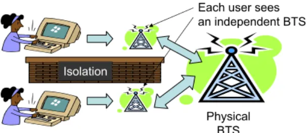
Figure 1: Conceptual illustration of ourvirtual
bases-tation design. Virtualization consists of three main concepts: Abstraction and programmability, which provide every slice with the experience of having control over a virtual basestation, and slice isolation which ensures performance repeatability.
as the transmission frequency, power, rate, symbol ratios, retransmission mechanisms, and other client management functionality. The BTS interacts with the wired world through the use of the ASN-GW. The ASN-GW is used to route traffic appropriately from the wired interface(s) to individ-ual service flows on WiMAX clients. After describing the requirements for our virtualized framework, we will discuss the modifications and additions needed to these components for realizing ourvirtual basestationdesign.
2.2
Requirements In A Shared BTS Setup
At a conceptual level, the system requirements are as described in Figure 1. Our system should provide every slice/user with the illusion that it has control of an entire basestation, though the radio capacity of this virtual BTS is possibly lesser than the original physical BTS. Such
vir-tual basestationsprovided to individual slices should have a control framework which is similar to the original basesta-tion. Finally, these virtual basestations should also be iso-lated from each other i.e, they should not affect each others performance.
Before we delve into the details of our design we will briefly discuss specific requirements which are important from two different perspectives. Though all requirements described in this section are specific to the deployment of a 802.16e Mo-bile WiMAX system, the requirements and corresponding design can be generalized to encompass the deployment of other 4Gcellular radios such as LTE [4].
Slice User’s Perspective.
We begin with a discussion on the design features impor-tant from a slice user’s i.e an MVNO’s or experimenter’s perspective:
• Layer-2 Frame Switching: To allow the user to run a custom network stack, which is a key requirement for evaluating the clean slate protocols, the complete datapath for the WiMAX system should be run purely using layer-2 switching.
• Programmability: Each of the slices should have ac-cess to most of the features that can be controlled on the Basestation. These include and are not limited to the use of custom service flow definitions and flow scheduling mechanisms.
Local vBTS#01 Slice Access Network eth0 eth1 Outside World Outside Bus (Trunk)
Local vBTS#N eth0 eth1 Remote vBTS eth0 IP Tunnel ASNSubstrate eth1 Instrumentation Network Base Station (BTS) eth1 eth0 Hardware Monitoring Services VM Bus (Trunk) Data Trunk
Outdoor Unit & Roof mounted Antenna
Wireless client
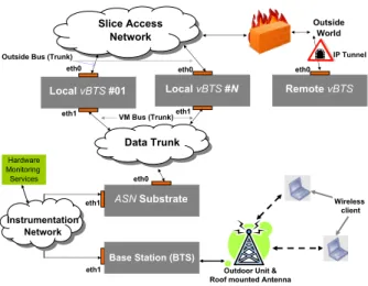
Figure 2: Generic architecture for the proposed
WiMAX deployment. This architecture is capable
of supporting mutiplevBTSsubstrates, which could
be either local or remotely located.
• Slice feedback: Appropriate feedback should be pro-vided to every slice for allowing measurements and performance monitoring. Detailed information such as RSSI, Modulation and coding scheme (MCS), through-put (Mbps), MAC retries, and the CINR ratio are among few of the metrics that are particularly useful for individual slices.
• Repeatability: Slices would want their results to be repeatable over time. Hence, even though the results are scaled down (due to sharing with other slices) they will still allow scientific inference to be drawn from experiments.
Administrator’s Perspective.
The system administrator will either be a mobile network operator or a testbed operator. Features which are impor-tant from such a system administrator’s perspective are as listed
below-• Slice management: Our setup should support cre-ation, destruction, and restoration of slice instances in the system. Such a feature should also support dy-namic creation, destruction or modification of the data path for individual slices. Other features under this category include quota management for slices such as CPU, disk or radio resources allocated per slice. • Monitoring services: Resource tracking services that
allow the system administrator to have a broad view of the system permits system usage control and diag-nostics. Typically, features such as details on authen-ticated clients, slices, traffic, current and historical re-source usage are useful.
Based on these design considerations, we present our
vir-tual basestationframework. We begin with a broad overview of the network architecture followed by a detailed design de-scription of individual components in the system.
eth1
eth1.vl1 eth1.vl2 eth1.vln
eth0
eth0.vl1 eth0.vl2 eth0.vln
eth2 vnet2 vnet0 vnet1 vBSn vBS Aggregate Manager vnet2 vnet0 vnet1 vBS2 vnet2 vnet0 vnet1 vBS1
Figure 3: Proposed architecture for the vBTS
sub-strate. VLANs are named as ethX.vly, where X is
the number of the physical interface and y denotes the vlan id on that interface.
2.3
Top-Down Design Overview
An architectural overview of our virtual basestation de-sign is as shown in Figure 2. In addition to the Bases-tation transceiver (BTS) and the Application service net-work (ASN-GW), which are standard components of the WiMAX framework, we add the virtual basestation (vBTS) substrate. Our idea of emulatingvBTSs outside of the phys-ical BTS is motivated from the fact that the BTS is a pro-prietary product, and in most cases we will not be able to modify its functionalities or features. Such a loosely coupled system design allows ourvirtual basestationframework to be portable across other BTS hardware platforms and improves its applicability.
Functionally, thevBTS substrate provides a platform for multiple slices to login and conduct experiments through the use of virtual machines. Each of the virtual basestations on the local3 vBTS substrate has an appropriate control and layer-2 datapath configured to reach the physical BTS transparently through the customized ASN-GW. The con-trol and customization of the slice are made feasible through appropriate grid service, while the layer-2 datapath is setup using features such as VLANs, tunnels at layer 2 and frame routing through the Click modular router. ThesevBTSs can now be leased by MVNOs from the operator or they can be directly included as a part of the GENI slices for performing end-to-end experimentation.
In the following sections, the paper will discuss the de-tails and rationale for the design of the virtual basestation substrate as well as the modified ASN-GW substrate.
3.
VIRTUAL BASESTATION SUBSTRATE
The main function of thevBTS substrate is to emulate an isolated private basestation transceiver for every slice. We begin with a generic discussion of the design methodol-ogy for thevBTS substrate, followed by a discussion on the components used for prototyping the substrate.
3.1
VM Technology Selection
The vBTS substrate fulfills the purpose of emulating a fully functional WiMAX Basestation Transceiver (BTS) to every slice user, while possibly supporting lesser (but fixed) radio capacity than the original BTS itself. To ensure that
all design requirements listed in the previous section 2 are fulfilled, we need to carefully select appropriate virtualiza-tion technology for running the virtual machines. Specif-ically, our virtual machine (VM) technology should: (1) Allow for quick creation and deletion of VM instances for management purposes, (2) Support a wide variety of OS distributions to allow customization of environment, (3) Al-low the user to customize everything from the Kernel (and hence the network stack) to the drivers used in the OS, and finally, (4) Provide means for easy administration. As per qualitative comparisons provided in a previous study [11], Full Virtualizationprovides each of these features and it is thus preferred over other forms of system virtualization for ourvBTS implementation.
We use Kernel Virtual Machines (KVM) [3] which are based on the QEMU [7] emulator. This is a full virtualiza-tion technique and relies on the CPU architecture to have virtualization extensions such asIntel VTorAMD-V. KVM can be easily administered from conventional Debian sys-tems, which are also used with our other systems in the ORBIT framework. KVM also has support for a wide vari-ety of distributions for the guest VMs, and supports virtual networking that allows creation of virtual interfaces.
3.2
Slice Access Design
A generalized design of thevBTS substrate is as shown in the Figure 3. Each of the VMs are designed to have three virtual interfaces, marked asvnet0 through2. These virtual interfaces are bridged with appropriate VLANs on corresponding physical interfaces. Individual vlan-ids serve as slice identifiers. Functionality provided by each of the virtual interfaces is discussed below.
GENI/Outside Access: The first virtual interfacevnet0 is responsible for providing connectivity to the outside world from the VM. This is achieved by bridging traffic from each vnet0 to the appropriate outbound VLAN interface. The slice user can also use SSH over this interface to enter into the VM. This interface is directly routable from the physical eth0 interface on thevBTS host machine.
Client Access: The second interface on the virtual ma-chine isvnet1, which is used by the slice user to reach the WiMAX clients via the BTS. Each of thesevnet1 interfaces are tunneled to individualvlans on theeth1 interface of the vBTS host machine. Thesevlans travel over the trunk and are eventually connected to the wireless clients through the modified ASN substrate as seen in Figure 2. Using vlans permits us to easily separate traffic from a slice at layer-2. Such a setup also helps in making the system design scalable, since thesevlans allow us to span thevBTS substrate over multiple physical machines connected over LANs. From a slice user’s perspective, every MAC (layer-2) frame destined to the wireless clients should be sent over this local interface in thevBTSenvironment, and similarly receive frames from the clients through the same interface.
Control Access: The third interface on each of the VMs is vnet24, which is a control interface connected via theeth2 interface on the node. This interface allows the experimenter to orchestrate the experiment, collect results, and eventually
4If physical machine which runs thevBTS substrate does
not have more than two ethernet interfaces, functionality provided by this control interface and the first interface for GENI access can be merged.
1 2 n
GRE1 GRE2 GRE3 GRE4 GRE5 GRE6
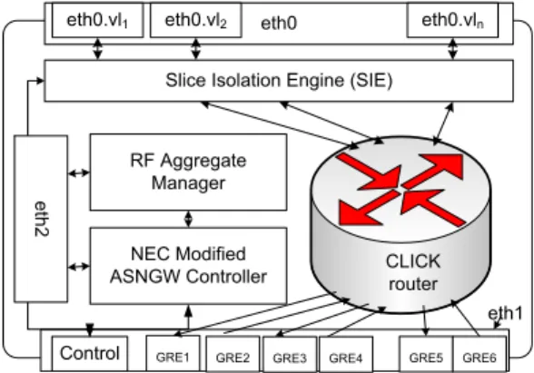
Figure 4: Modified ASN-GW substrate.
provide means of remote monitoring using the vBTS man-agement services.
3.3
VM Grid Services
Programmability within each of the virtual machines is provided through a restful web interface which is a cus-tomized version of the OMF [5] grid service. OMF was chosen as an experiment control and management frame-work because it provides an easy, centralized approach to resource management. Most of the control and monitoring features supported by the OMF grid service are web-based, which can be accessed remotely through a browser inter-face or programmable web requests. The virtualization API exposed through the grid service allows every slice user to control virtual machine interfaces, add wireless clients to the slice, managevlansand control local datapath creation, con-figure parameters for the clients, create custom service flows and finally also collect results from the experiment. Details of this grid service design will be addressed in a separate study. We will now discuss the modifications for the ASN-GW substrate, followed by preliminary evaluations on the platform.
4.
MODIFIED ASN-GW FUNCTIONALITY
The access service network gateway (ASN-GW) performs the function of a gateway for the BTS. Depending on the profile of the WiMAX system, the ASN may also provide other functionality such as radio resource management. In this section, we will discuss modifications made to the ASN substrate to support a virtualized mode of operation with thevBTS substrate. The design of our modified ASN is as shown in the Figure 4. Changes are made both on the con-trol and data path. On the data path, the ASN is modified for dynamically channeling traffic from individualvlan inter-faces (from thevBTS substrate) to appropriategretunnels terminating in the BTS. Another important data path com-ponent of ourvirtual basestationframework is a flexible slice isolation engine that allows for control of radio resources used by individual slices. On the control path, the R6 inter-face is modified to change the way wireless clients are han-dled, thus allowing better control for data path mapping. We will now discuss the design of individual components of the modified ASN-GW in detail.
Slice ManagervBTS ManagerASN ControllerNEC R6 Create slice VM Creation Status addClient() VLAN Creation Propagate Mapping Update vMap table (MAC Ægre) Update vMap table (MAC Ægre) Status: datapath Complete/incomplete Status
Update vMap table (VLAN ÆMAC)
registration
Association status
registration
Association status
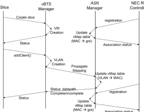
Figure 5: An example of message passing in the sys-tem. The figure depicts the interaction among com-ponents of the system when a slice adds a client, and a mobile client actually registers with the system.
4.1
Modified ASN Datapath
The ASN substrate is responsible for acting as a transpar-ent gateway between thevBTSs and the actual air interface. Since all packet switching has to happen at Layer-2, we re-moved the IP routing from the conventional ASN-GW setup and use Click [12, 1] for frame redirection. All packet clas-sification is based on slice identifiers, VLANids, and MAC addresses. The management architecture on thevBTS sub-strate sends the client MAC information for every slice as per individual requests to the RF aggregate manager. Typi-cally, this information allows the ASN to bridge traffic from the individual VLAN devices (on eth0) to correspondinggre tunnels ending in the BTS, which transmits and receives information from the wireless clients. Using mapping infor-mation obtained from thevBTS, the ASN bridges appropri-atevlan devices to thegretunnels. Though thegre tunnels themselves are layer-3 devices, we do not use any layer-3 routing. Standard five tuple classifiers (Source IP, Destina-tion IP, Source Port, DestinaDestina-tion Port, TOS) can be used in addition to our switching mechanism to redirect client traffic to the correctgre tunnels, which represent different service classes across clients. To maintain radio isolation across clients and slices, we provide the slice isolation en-gine (SIE), which is briefly discussed later.
4.2
Modified R6 Control Path
The R6 Controller provided with the NEC Basestation is a proprietary software module that manages the NEC bases-tation and provides various funtionalities like mobility, au-thentication, user data handling, QoS Management. It com-municates with the basestation using the R6 interface. Some part of the R6 interface is standardized in the WiMAX Net-work Forum. However, some interfaces and definitions are proprietary to NEC. For this reason, this module is available in a binary-only format. Extensions provided by this module are a socket based interface to notify client association and dissociation as client MAC-GRE pairs, and mechanisms for access control based on the client MAC identifiers. These extensions will help the RF Manager to setup the datapath and hence establish connectivity to the clients. We envision
that a component providing this very basic functionality will be supported by most manufacturers, thereby facilitating deployment across diverse platforms.
4.3
Slice Isolation Engine
The slice isolation engine (SIE) is a traffic shaping mech-anism that limits slice traffic irrespective of the clients and service classes used, such that the fraction of radio resource used by each slice are as per slice allocation policies. Though the NEC BTS supports time fairness of individual flows within the same priority class, for the sake of portability to other BTS hardware versions, and to provision weighted fairness across priority classes, ourvirtual basestation frame-work provides explicit isolation support. In addition to these features, our framework provides isolation across groups of flows (slices), which are a logical entity existing outside of the BTS.
Providing slice isolation is important since it helps to en-sure the flexibility and repeatability of experiments. The slice isolation engine throttles throughput of individual slices (flow groups) based on allocated slice quotas, and estimated downlink transmission rate. In case of the slice having more than one client, we compute aggregate downlink physical rate for the slice using three strategies: (1) Simple/weighted average, (2) Median rate estimate, and a more complex (3) Feedback based slice rate estimate mechanism. For brevity, we do not discuss these in this section. The SIE runs as a closed loop control mechanism on the modified ASN that constantly estimates performance of clients belonging to in-dividual slices, and uses this information to control down-link traffic. We use the element handlers supported by the Click [12] that allows re-configuration of preset parameters at runtime. A first generation implementation of the slice isolation engine is discussed in a previous study [10].
4.4
Basic Experiment Setup
An example of message passing between different entities in the system for slice creation, client registration, and ad-dition of clients to slices is as shown in Figure 5. The ex-periment begins with the slice/user requesting for a vBTS creation. In response, thevBTS aggregate manager creates an appropriate VM instance, sets up networking from the VM to thevlan, and returns the status of the operation. If thevBTS creation is successful, the slice requests for addi-tion of a wireless WiMAX client to its instance by specifying its MAC address. ThevBTS aggregate manager sends this information to the RF aggregate manager that populates an entry in a mapping table. Typically, the fields in this table are: vlan−id,vm−name,client−M AC,client−gre, and gre direction. Out of these, the first three entries are pro-vided by thevBTS aggregate manager. Theclient−M AC
to gre mapping information is made available by the NEC modified ASN controller to the RF aggregate manager on the ASN substrate. In the mapping table, theclient−M AC is used to uniquely identify every entry. When all entries are populated in a row of the mapping table, an end to end data path is automatically setup in Click [1]5.
5Typically, these datapath modifications are envisioned
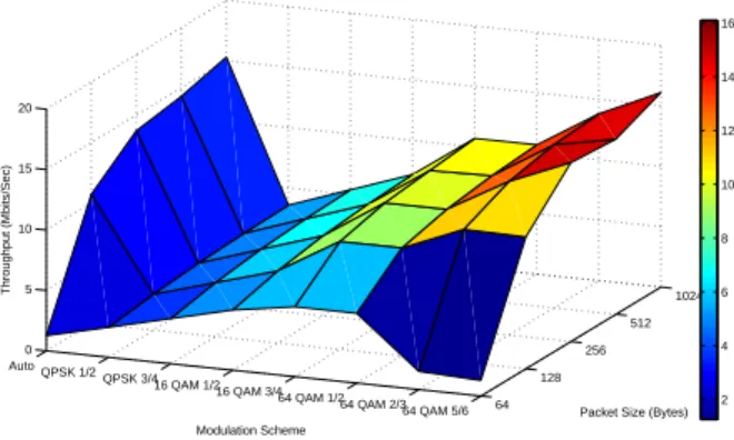
64 128 256 512 1024 64 QAM 5/6 64 QAM 2/3 64 QAM 1/2 16 QAM 3/4 16 QAM 1/2 QPSK 3/4 QPSK 1/2 Auto 0 5 10 15 20
Packet Size (Bytes) Modulation Scheme Throughput (Mbits/Sec) 2 4 6 8 10 12 14 16
Figure 6: Baseline throughput measurements.
P arameter V alue
Basestation Manufacturer NEC
Profile A
Channel 2.5Ghz
Bandwidth 10Mhz
Default Service Flow BE
DL/UL ratio 35:12
Traffic Type UDP
Packet size 1024bytes
Link adaptation Enabled
Client Chipset Beceem
Figure 7: Default parameters used with all exper-iments unless mentioned otherwise in the experi-ment.
5.
EXPERIMENTAL EVALUATION
To demonstrate the performance of our design we perform some baseline experiments. Initially, we will show the per-formance achievable with the basestation itself, followed by setups involving sample experiment scenarios. Experimen-tal parameters for the NEC basestation are as shown in Fig-ure 7, and are used as default parameters unless described explicitly in the experiment.
5.1
Raw UDP Throughput Performance
In this setup, we study the baseline downlink throughput performance of the WiMAX basestation transceiver. The client is located at a location which is very close to the basestation, though there is no line of sight link between the client and the BTS antenna. The observed CINR is 29dB and RSSI is -51dB. To evaluate the performance we measure UDP throughput for different frame sizes and dif-ferent modulation and coding schemes (MCSs) used to reach the client.
Downlink throughput measurements obtained from the experiment are as shown in Figure 6. We observe that the throughput performance is the best for large frame sizes and improves with the use of higher bit rate MCSs. This be-havior is justified since the client has a good connection to the BTS, which results in superior performance with higher rate MCSs. We also observe that the auto rate scheme used at the Basestation is capable of matching the performance
Time (secs) RSSI (dBm) ORBIT Testbed Conf. Room Roof Antenna
Figure 8: Experiment topology for indoor Femtocell emulation experiment. Position of stationary client is fixed in the control room, and the mobile client moves along the marked trajectory.
0 20 40 60 80 100 0 1 2 3 4 5 6 7 8 9
Experiment Duration (secs)
Observed Throughput (Mbps) Slice 1 − Without vBTS Slice 2 − Without vBTS Slice 1 − vBTS
Figure 9: Throughput performance of individual
slices as a function of time. Shown in the results
is performance with BE service flows in each class.
achieved by static rates. This serves as a baseline test to validate performance of the autorate algorithm on the BTS.
5.2
BE-BE Slice Isolation
This experiment emulates mobility in a Femtocell deploy-ment, and is repeated in all further indoor measurements. We consider two slices which are sending traffic fromvBTS1 andvBTS2 to their corresponding clients. Client for the flow fromvBTS1 (slice1) is stationary, and the client for the flow fromvBTS2 (slice2) is mobile. The link from each VM to the corresponding client constitutes of a slice. The station-ary client is located such that it has a CINR greater than 30 which allows the basestation to send traffic comfortably at 64QAM56 . An experimenter walks with the mobile client as per the coverage map shown in the Figure 8. As per the RSSI trace for the walk, the link degrades in a corner of the corridor and improves as the experimenter returns to the starting position. Each slice is configured to saturate the link to its client with UDP traffic.
The observed downlink throughput for both the clients without any shaping is as shown in Figure 9. We observe
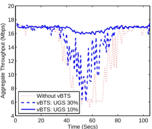
0 20 40 60 80 100 4 6 8 10 12 14 16 18 20 Time (Secs)
Aggregate Throughput (Mbps) Without vBTS vBTS: UGS 30% vBTS: UGS 10%
Figure 10: Throughput performance of individual
slices as a function of time. Shown in the results
is performance with BE service flow for the static client and UGS service flow for the mobile client.
that as the mobile client reaches areas where the RSSI drops below a certain threshold, the rate adaptation scheme at the basestation selects a more robust modulation and cod-ing scheme(MCS). However, in the process the link with the mobile client ends up consuming a lot more radio resource at the basestation, which affects performance of the station-ary client. Thus we observe that while the BS scheduler is capable of providing QoS, it does not ensure radio resource fairness across links. The NEC BTS features a time-fair mode for providing fairness across flows of the same class, that could alleviate this condition. However, we use this case as a baseline to demonstrate the performance of our isola-tion engine (SIE) in thevirtual basestationframework, and we will eventually show that our scheme can work across service classes and flow-groups. Results from the experi-ment repeated with our isolation engine are as shown in the Figure 9. Even as the channel for the mobile client dete-riorates, our framework is able to appropriately limit the basestation utilization for the mobile client (slice) thereby providing fairness to the stationary client.
5.3
UGS-BE Slice Isolation
We will now extend results from the previous experiment by comparing the performance of slice isolation scheme across different traffic classes. To justify the performance we will consider an extreme condition where the slice with the mo-bile client is using unsolicited grant service (UGS) flows. UGS flows are typically used for voice services (VOIP) and are given priority over all other service flow types. The static client uses best effort (BE) flows, which have no reservation. We repeat the previously discussed experiment, and plot the total throughput for both clients in Figure 10. An initial run of the experiment is performed without our framework, followed by varying reservation for the UGS flow. When we do not have any slice scheduling through our framework, the total throughput suffers when the UGS client traverses through the region with poor coverage. This is because the basestation frame scheduler tries to ensure all the traffic to the mobile client is delivered, while resulting in a very poor throughput performance for the static client. However, we notice that by using our virtual basestationframework, we
UGS UGS
ERTPS RTPS NRTPS BE ERTPS RTPS NRTPS BE
BSFrame Scheduler Experiment
Slice # 01 Experiment Slice # 02
Slice Quotas Slice - 2 Scheduler Slice -1 Scheduler
Slice Isolation Engine
Figure 11: Hierarchical slice scheduling for allowing every slice to have a custom frame scheduler.
are able to limit airtime allocated to the UGS client, thus improving overall throughput performance when the client traverses through the region with poor coverage.
5.4
Customized Scheduler Evaluation
Understanding and optimizing the MAC scheduling frame-work on the wireless edge presents an important avenue for improving end-to-end performance of specialized services such as voice, video or bulk file transfers. Customizing the MAC scheduling framework also provides a means of service differentiation which could help MVNOs to attract customers. As a part of our framework, one of the design goals was to allow the emulation of multiple MAC sched-ulers within different vBTSs. Since our mechanism allows isolation of a fixed percentage of the BTSs radio resources, every slice can use a custom scheduler to allocate these re-sources to their clients. The effective conceptual setup of the system is as shown in Figure 11. The design is based on a hierarchical scheduling mechanism where we have custom flow scheduling within the slice which is run as a part of the VM, possibly by an MVNO (which leases the slice) or an experimenter. At a lower layer, the slice scheduler (SIE) provided by our framework, will limit traffic from individual slices, thus preventing any inter-slice interference.
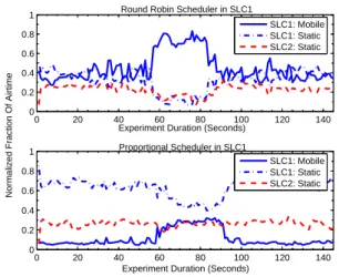
As an example, we show the performance of two flow schedulers implemented within the first slice: (1) Round robin: which alternately sends a packet for each of its two clients, and a simple proportional scheduler. (2) The pro-portional scheduler sends 85% of the allocated traffic to one client and the remainder packets for the other client. The first slice SLC1 has two clients: a static client, and a mobile client that follows the trajectory described in Figure 8. The second slice SLC2 has a single static client that has simi-lar channel conditions to the static client in SLC1. Since SLC2 has a single client, it does not need a flow scheduling mechanism. We send downlink UDP traffic at saturation to each of these clients. Measured fraction of airtime used by the clients during the course of the experiment are as shown in Figure 12. We observe that when the first slice uses a simple round-robin scheduler, both clients in SLC 1 get similar airtime when channel quality is good for the mo-bile client. However, as the momo-bile client passes through the area with poor coverage, the airtime consumed by the mo-bile client increases, leading to a corresponding decrease in airtime available to the static client in SLC1. We observe that our slice isolation engine which is a part of thevirtual
0 20 40 60 80 100 120 140 0 0.2 0.4 0.6 0.8 1
Experiment Duration (Seconds) Round Robin Scheduler in SLC1
0 20 40 60 80 100 120 140 0 0.2 0.4 0.6 0.8 1
Experiment Duration (Seconds)
Normalized Fraction Of Airtime
Proportional Scheduler in SLC1 SLC1: Mobile SLC1: Static SLC2: Static SLC1: Mobile SLC1: Static SLC2: Static
Figure 12: Airtime utilization with two custom
scheduling schemes for the scheduler running within the first slice.
basestationframework succeeds in preventing SLC1 from us-ing airtime allocated for SLC2. A similar performance iso-lation is seen when the experiment is repeated with a pro-portional flow scheduler in SLC1. Hence, this experiment shows that each of individual slices could run a custom flow scheduler without affecting performance of other slices, thus making experiments repeatable and isolated. This flexibil-ity provided by ourvirtual basestationframework makes it an attractive candidate for deployment in both experimental testbeds and for hosting MVNOs.
6.
RELATED WORK
Previous testbed virtualization efforts like the Planetlab [14] have primarily focussed on wired testbed virtualization. In the case of wireless devices, one of the first approaches to virtualize was proposed for short range WiFi radios in the form of virtual access points(VAPs) [9]. VAPs were proposed as abstractions on a physical AP, such that the functional-ity provided by the VAP was similar to that of an AP. Our approach to virtualizing the wireless radio differs from the VAP approach since the VAP is usually emulated by making changes to the device driver on the access point, thus mak-ing the solution dependent on the AP hardware (chipset) as well as the drivers needed for controlling the chipset. By building thevirtual basestationas a logical entity outside of the actual commercial BTS, we make our design hardware independent.
One of the few virtual basestation designs is the VANU MultiRAN virtual basestation design [8]. The VANU design aims at running the entire virtualized BTS radio in software while our design approach relies on leveraging commercial carrier grade BTSs, and builds around them for providing virtualization. A similar approach is followed by the Open Basestation project [6] which relies on implementing a 2G BTS in software, though it does not support virtualization. Another study [16] discusses approaches in which the net-work architecture may be emulated using virtual machines, but does not deal with the emulation of the radio itself.
7.
CONCLUSIONS
Network virtualization provides a convenient means of sharing resources across a wide set of users while allowing in-tegration with other virtualized substrates. We present our
virtual basestationframework for seamless sharing of a single physical basestation which could be implemented both by testbed operators and mobile network operators. Primarily, we discuss the approach used for emulating virtual wireless basestations to multiple slices, while also providing isola-tion to ensure repeatability of results. Representative results from over-the-air experiments are provided for baseline per-formance validation, isolation testing, and demonstration of custom flow scheduling using our framework. Future work involves a more detailed analysis of custom flow scheduling mechanisms used in conjunction with different underlying slice isolation strategies.
8.
REFERENCES
[1] Click modular router.http://read.cs.ucla.edu/click/. [2] GENI.http://www.geni.net/.
[3] KVM.http://www.linux−kvm.org/.
[4] Long term evolution.http://www.3gpp.org/LTE. [5] Omf framework.http://omf.mytestbed.net/. [6] The openbts project.
http://openbts.sourcef orge.net/.
[7] QEMU emulator.http://www.qemu.org/. [8] Vanu multiran virtual basestation.
http://tinyurl.com/22lka2f.
[9] B. Aboba. Virtual access points, ieee document, ieee 802.11-03/154r1.http://tinyurl.com/yjjkwpv.
[10] G. Bhanage, R. Daya, I. Seskar, and D. Raychaudhuri. VNTS: a virtual network traffic shaper for air time fairness in 802:16e slices. InIEEE ICC - Wireless and Mobile Networking Symposium, South Africa, 5 2010. [11] G. Bhanage, I. Seskar, Y. Zhang, D. Raychaudhuri,
and S. Jain. Experimental evaluation of openvz from a testbed deployment perspective. InICST Tridentcom, Berlin, Germany, 5 2010.
[12] E. Kohler, R. Morris, B. Chen, J. Jannotti, and M. F. Kaashoek. The click modular router.ACM Trans. Comput. Syst., 18(3), 2000.
[13] Mike Hibler and Robert Ricci and Leigh Stoller and Jonathon Duerig and Shashi Guruprasad and Tim Stacky and Kirk Webby and Jay Lepreau. Large-scale Virtualization in the Emulab Network Testbed. In USENIX, 2008.
[14] L. Peterson, S. Muir, T. Roscoe, and A. Klingaman. PlanetLab Architecture: An Overview. Technical Report PDN–06–031, May 2006.
[15] D. Raychaudhuri, M. Ott, and I. Seskar. Orbit radio grid tested for evaluation of next-generation wireless network protocols. InIn proceedings of IEEE TRIDENTCOM, pages 308–309, 2005. [16] M. G. Rodr´ıguez, F. G. M´arquez, and E. J.
Torres Mateos. A 3gpp system architecture evolution virtualized experimentation infrastructure for mobility prototyping. InProceedings of TridentCom, pages 1–10, ICST, Brussels, Belgium, Belgium, 2008.