Proceedings of the
Ninth International Workshop on
Graph Transformation and
Visual Modeling Techniques
(GT-VMT 2010)
Verification of Model Transformations
Bernhard Sch¨atz
13 pages
Guest Editors: Jochen K ¨uster, Emilio Tuosto
Managing Editors: Tiziana Margaria, Julia Padberg, Gabriele Taentzer
Verification of Model Transformations
Bernhard Sch¨atz
fortiss GmbH
Guerickestr. 25, 80805 Mnchen, Germany
Abstract: With the increasing use of automatic transformations of models, the correctness of these transformations becomes an increasingly important issue. Es-pecially for model transformation generally defined using abstract description tech-niques like graph transformations or declarative relational specifications, however, establishing the soundness of those transformations by test-based approaches is not straight-forward. We show how formal verification of soundness conditions over such declarative relational style transformations can be performed using an inter-active theorem prover. The relational style allows a direct translation of transfor-mations as well as associated soundness conditions into corresponding axioms and theorems. Using the Isabelle theorem prover, the approach is demonstrated for a refactoring transformation and a connectedness soundness condition.
Keywords:Model transformation, rule-based, verification, theorem prover
1
Motivation
The construction of increasingly sophisticated software products has led to widening gap be-tween the required and supplied productivity in software development. To overcome the com-plexity of realistic software systems and thus increase productivity, current approaches increas-ingly focus on a model-baseddevelopment using appropriate description techniques. Besides increasing efficiency, these transformations can offer consistency ensuring modification of mod-els, ranging from refactoring steps to improve the architecture of a system to the consistent integration of standard behavior. However, with the increased use of transformation, the ques-tion of the correctness of transformaques-tions arises: How can we verify that the models constructed via transformation are ‘well-formed’ given a ‘well-formed’ source model, e.g., by ensuring that no relevant elements of the source model are absent in the target model. Obviously, testing is one possible way of ensuring the correctness of transformations. However, concepts like cov-erage etc. are not immediately transferable to model-transformations, especially if those are rules-based or declarative.
1.1 Related Approaches
Verification of model transformations has been specifically investigated for graph-based trans-formation technquies (e.g., [GGL+06] and [Str08]). In that respect, the presented approach is similar: The introduced transformation framework is used to describe graph transformations, us-ing a relational calculus focused on basic constructs to manipulate nodes (elements) and edges (relations) of a conceptual model. A theorem prover based on on high-order logics is used to prove characteristics of the transformation by deducing properties of the target model from some properties of the source model.
In contrast to other graph-based approaches like MOFLON/TGG [KKS07], Viatra [VP04], or FuJaBa [GGL05], however, here the specification of transformations is not based on triple graph-grammars or graphical, rule-based descriptions, but uses a textual description based on a relational, declarative calculus. Therefore, in contrast to those approaches, the approach intro-duced here uses only a single formalism to describe basic transformations as well as their com-positions.Furthermore, only a single homogenous formalism with two simple construction/de-construction operators to describe the basic transformation rules and their composition; complex analysis or transformation steps can be easily modularized since there are no side-effects or in-cremental changes during the transformation. Thus, a specification can be immediately used for verification without complex translations; furthermore, proofs on the formal level more directly reflect intuitive reasoning about the transformation.
This homogeneity is especially important for verification since is drastically simplifies the con-struction of proofs: [GGL+06] focusses on TGG-based translation and therefore uses substantial proof parts to model (and verify) the effective construction of correspondence graphs to describe the application of individual graph rules. Furthermore – due to that approach – there struc-tural induction over the pre/post-models is used which is less convenient when if non-translation transformations are verified. Here, in contrast, induction over the transformation itself rather than the pre/post models is performed, thus having a more direct proof principle and avoiding the proof overhead of correspondence graphs and applicability conditions. Similarly, [Str08], – usingIsabelleas theorem proving support, too – also requires substantial effort to specify and verify correspondence graph and application conditions for single transformation rules as well their combination usingwhile andcaseconstructs. Thus, the application and ordering of rules providedimplicitly by a TGG approach has to be verifiedexplicitly and using rather different proof principles. In contrast, here, a more direct and homogenous form of proof is supported by the declarative rule-based style. [CR09] uses a relational description of graphs similar to the presented approach as well as similar proof principles. However, neither is their formalism is supported by an executable implementation nor do they use mechanic proof support.
a rule-based description of transformations.
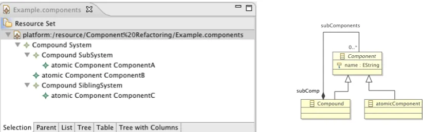
Figure 1: Example of Hierarchical Component Model and Corresponding Conceptual Model
1.2 Overview and Contribution
As the main contribution, an approach to formally verify model transformations is presented in the following sections. The approach is based on a transformation of EMF Ecore models using a completelydeclarative relationalstyle in arule-based fashion, introduced in [Sch08]. To provide such a form of transformations, the approach uses a term-based formalization of an EMF model as shown in Section2. With this form of model representation, as shown in Section3
transformations can be described as declarative relations in Prolog style, supporting rules similar to graph grammars as a specific description style.
Based on these previously established results, asnew contributionin Section4the suitability of this declarative relational style of defining models and transformation rules for the verification of transformations is shown: The formalization of (meta-)models and transformation rules can be directly translated in representations suited for theorem provers for predicate logic likeIsabelle; furthermore, due to the relational style correctness proofs of transformations can be performed by reasoning on the level of their specifications. Section5highlights some benefits and open issues.
2
Model Structure
To provide verified transformations of descriptions of systems, first the means of specifying a system in form of a system model is needed. The left-hand side of Figure1 shows such a model, describing the hierarchical structure of the components of a system: the systemSystem, consisting of subcomponentsSubSystem,ComponentB, andSiblingSystem, the first and the last with subcomponentsComponentAandComponentC, resp.1
To construct formalized descriptions of a system under development, a ‘syntactic vocabulary’ is needed. This conceptual model2characterizes all possible system models built from the mod-eling concepts and their relations used to construct a description of a system; typically, class
1 For simplification, here only components and their containment-relation is modeled; other typical aspects like
interfaces or communication links are ignored.
2In the context of technologies like the Meta Object Facility, the class diagram-like definition of a conceptual model
diagrams are used to describe them. The right-hand side of Figure1shows the corresponding conceptual model – with the concept of aComponentwith an attributenameand asubComp -relation – used to describe the architectural structure of a system.
2.1 Structure of the Model
The transformation framework provides mechanisms for a pure (i.e., side-effect free) declarative, rule-based approach to model transformation, accessing EMF Ecore-based models [SBPM07]. Based on the conceptual model, a system model consists of sets of elements (each described as a conceptual entity and its attribute values) and relations (each described as a pair of conceptual entities), syntactically represented as a Prolog term. Since these elements and relations are in-stances of classes and associations taken from an EMF Ecore model, the structure of the Prolog term – representing an instance model – is inferred from the structure of that model. The structure of the model is built using only simple elementary Prolog constructs, namely compound functor terms and list terms. To access a model, the framework provides predicates to deconstruct and reconstruct a term representing a model. [Sch08] describes the model in more detail.
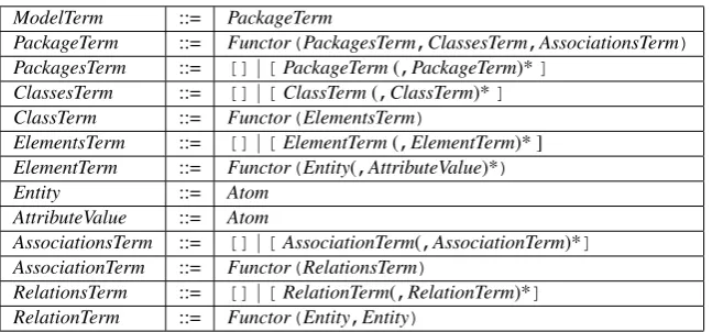
A model term describes an instance of a EMF Ecore model. Each model term is a list of package terms, one for each packages of the EMF Ecore model. Each package term, in turn, describes the content of the package instance. It consists of a functor, identifying the package, with a packages term, a classes terms, and an associations term as its argument. The sub-packages term describes the sub-sub-packages of the package; it is a list of package terms.
The classes term describes the EClasses of the corresponding package. It is a list of class terms, one for each EClass. Eachclass termconsists of a functor, identifying the class, and an elements term. Anelements termdescribes the collection of objects instantiating this class, and thus is a list of element terms. Finally, anelement termconsists of a functor, identifying the class this object belongs to, with an entity identifying the element and attributes as arguments. Each of the attributes are atomic representations of the corresponding values of the attributes of the represented object. The entity is a regular atom, unique for each element term.
Similarly to an elements term, eachassociations termdescribes the associations, i.e., the in-stances of the EReferences of the EClasses, for the corresponding package. Again, it is a list of association terms, with eachassociation termconsisting of a functor, identifying the association, and an relations term, describing the content of the association. Therelations termis a list of relation terms, eachrelation termconsisting of a functor, identifying the relation, and the entity identificators of the related objects. In detail, the Prolog model term has the structure shown in Table1in the BNF notation with correspondingnon-terminalsandterminals.3
The functors of the compound terms are deduced from the EMF Ecore model: The functor of a PackageTerm from the name of the EPackage; the functor of a ClassTerm from the name of the EClass; the functor of an AssociationTerm from the name of the EReference. Similarly, the atoms of the attributes are deduced from the instance of the EMF Ecore model, which the model term is representing: The entity atom corresponds to the object identificator of an instance of a EClass, while the attribute corresponds to the attribute value of an instance of an EClass.
3While actually aModelTermconsists of a set ofPackageTerms, here for simplification purposes only one
ModelTerm ::= PackageTerm
PackageTerm ::= Functor(PackagesTerm,ClassesTerm,AssociationsTerm)
PackagesTerm ::= []|[PackageTerm(,PackageTerm)*]
ClassesTerm ::= []|[ClassTerm(,ClassTerm)*]
ClassTerm ::= Functor(ElementsTerm)
ElementsTerm ::= []|[ElementTerm(,ElementTerm)* ] ElementTerm ::= Functor(Entity(,AttributeValue)*)
Entity ::= Atom AttributeValue ::= Atom
AssociationsTerm ::= []|[AssociationTerm(,AssociationTerm)*]
AssociationTerm ::= Functor(RelationsTerm)
RelationsTerm ::= []|[RelationTerm(,RelationTerm)*]
RelationTerm ::= Functor(Entity,Entity)
Table 1: The Prolog Structure of a Model Term
2.2 Construction Predicates
In a strictly declarative rule-based approach, the transformation is described in terms of a predi-cate, relating the models before and after the transformation. Therefore, mechanisms are needed in form of predicates to deconstruct a model into its parts as well as to construct a model from its parts. As the structure of the model is defined using only compound functor terms and list terms, only two forms of predicates are needed: union and composition operations.
2.2.1 List Construction
The(de)construction of lists is managed by means of the union predicateunion/3with tem-plate4 union(?Left,?Right,?All) such that union(Left,Right,All) is true if
all elements of list All are either elements of Left or Right, and vice versa. Thus, e.g., union([1, 3,5],R,[1,2,3,4,5])succeeds withR = [2,4].
2.2.2 Compound Construction
Since the compound structures used to build the model instances depend on the actual structure of the EMF Ecore model, only the general schemata used are described. In all three schemata – package, class/element, or association/relation – the name of the package, class, or relation is used as the name of the predicate for the compound construction.
Packages For (de)construction of packages, package predicates of the form package/4 are used with template package(?Package,?Subpackages, ?Clas-ses,?Associations)where package is the name of the package (de)constructed. Thus, e.g., a package namedArchitecturein the EMF Ecore model is represented by the compound constructor Architecture. The predicate is true if Package consists of subpackages Subpackages, classesClasses, and associationsAssociations.
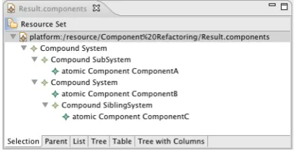
Figure 2: Example: Result of ClusteringComponentBandSiblingSystem
Classes and Elements For (de)construction of – non-abstract – classes/elements, class/ele-ment predicates of the form class/2 andclass/N+2 are used where N is the number of the attributes of the corresponding class, with templates class(?Class, ?Elements) andclass(?Element,?Entity,?Attr1,...,?AttrN)where class is the name of the class and element (de)constructed. Thus, e.g., the class namedCompound in the EMF Ecore model in Figure1 is represented by the compound constructor Compound. The class predi-cate is true if Class is the list ofObjects; it is used to deconstruct a class into its list of objects, and vice versa. Similarly, the element predicate is true if Element is an Entity with attributesAttr1,. . . ,AttrN; it can be used to deconstruct an element into its entity and attributes, to construct an element from an entity and attributes (e.g. to change the attributes of an element), or to construct a new element including its entity from the attributes. Thus, e.g., Compound(Compounds,[Sys,Sub,Sib])is used to construct a classCompoundsfrom a list of objectsSys,Sub, andSib. Similarly,Compound(Sub,Subsys,"SubSystem") is used to construct a new elementSubwith entitySubsys, and name"SubSystem".
1 cluster(Pre,Group,Post) :−
2 Architecture(Pre,Pack,PreClass,PreAssoc),
3 Compound(PreComp,PreComps),union(OtherClass,[PreComp],PreClass), 4 subComp(PreSub,PreSubs),union(OtherAssoc,[PreSub],PreAssoc), 5 link(PreSubs,Group,PreRoot,OutSubs),
6 Compound(PreRootComp,PreRoot,Name),union([PreRootComp],Comps,PreComps), 7 subComp(NewSub,PostRoot,PreRoot),union([NewSub],OutSubs,InSubs),
8 Compound(PostRootComp,PostRoot,Name),union([PreRootComp,PostRootComp],Comps,PostComps), 9 link(PostSubs,Group,PostRoot,InSubs),
10 subComp(PostSub,PostSubs),union(OtherAssoc,[PostSub],PostAssoc), 11 Compound(PostComp,PostComps),union(OtherClass,[PostComp],PostClass), 12 Architecture(Post,Pack,PostClass,PostAssoc).
Figure 3: Cluster-Transformation: Rule for (De-)Constructing the Model
3
Transformation Definition
The conceptual model and its structure defined in Section2was introduced to define transforma-tions of system models as shown in the left-hand side of Figure1. A typical transformation step is the clustering of a group of sibling components within a container component, making them subcomponents of that container. Figure2shows the result of such a transformation clustering subcomponentsComponentBandSiblingSystem of componentSystemin Figure 1into a new Systemcontainer. Besides introducing the new additional component Systemand making it a subcomponent of the originalSystemroot component, the transformation also requires changing the supercomponent ofComponentBandSiblingSystem.
In a relational approach to model transformations, such a transformation is described as a relation between the model prior to the transformation (e.g., as given in the left-hand side of Figure1) and the model after the transformation (e.g., as given in Figure2). In this section, the basic principles of describing transformations as relations are described.
3.1 Transformations as Relations
In case of the clustering operation, the relation describing the transformation has the interface cluster(Pre,Group,Post)with parameterPrefor the model before the transformation, parameterPostfor the model after the transformation, and parameterGroupfor the group of components of the model to be clustered. In the relational approach presented here, a transfor-mation is basically described by breaking down the pre-model into its constituents and build up the post-model from those constituents using the relations from Section2, potentially adding or removing elements and relations. WithPretaken from the conceptual domain described in Fig-ure1and packaged in a single packageArchitecturewith no sub-packages, it can be decomposed in contained classes (e.g.,Compound) and associations (e.g., subComp) as shown in Figure3, lines2to4.5 In the same fashion,Postcan be composed in lines12to10. Lines6to8obtain theName of the common super-component with entity PreRootof the group (line6), provide
5 For ease of reading, quotes required in Prolog for capital functor identifiers likeArchitectureorCompoundare
1 link(Subs,[],Root,Subs).
2 link(InSubs,Group,Root,OutSubs) :−
3 subComp(SubRel,Sub,Root),union([Sub],Rest,Group),union([SubRel],Subs,InSubs), 4 link(Subs,Rest,Root,OutSubs).
Figure 4: Cluster-Transformation: Rule for (Un-)Linking SubComponents
a newly created compound container componentPostRootCompthisNameand entityPostRoot
(line8), and make thisPreRootthe super-component ofPostRoot(line7). Note that the relation is bidirectional: Besides clustering a group of siblings into a common container, it can also be used to uncluster the group of subcomponents contained in a common container.
Besides using the basic relations to construct and deconstruct models (and add or remove elements and relations, as shown in the next subsection), new relations can be defined to support a modular description of transformation, decomposing rules into sub-rules. E.g., in thecluster relation, the transformation can be decomposed into the addition of the new container component and the reallocation of the components to be clustered; for the latter, then a sub-relationlink with corresponding rules is introduced, as shown in Figure4. Note thatlinkis effectively used in both directions in theclusterrelation: In line5, linkis used to unlink subcomponents by removing thesubComp-associations betweenGroup elements and the original component
PreRoot from PreSubsto obtain OutSubs; in line 9, link is used to link subcomponents by adding thesubComp-associations betweenGroupelements and the new componentPostRootto
InSubsto obtainPostSubs.
3.2 Transformations as Rules
To define the transformation steps for (un)linking components and subcomponents, relation link(InSubs,Group,Root,OutSubs) is used, by making the set OutSubs of associa-tions the reduction of setInSubswhen removing allsubComp-associations between elements fromGroup andRoot. The (un)linking of a group depends on whether the group is empty or not. Therefore, in a declarative approach, two different – recursive – (un)link rules for those two cases are needed, each with the interface described above.
To define these rules as shown in Figure4, the conceptual model and its structured represen-tation introduced in Section2are used. Line1simply states that in case of an empty group the sets of associations are the same since no elements can be (un)linked. This case also handles the termination of the inductive rule definition. In case of a non-empty group, line3(un)links aSub
4
Verification
The relational and declarative approach introduced in the previous sections supports an easy transition to formal reasoning. In this section, the formalization of an EMF Ecore meta-model in constructive type theory is presented, as well as the straight-forward formalization of transfor-mations. Based on these formalizations, the construction of formal correctness proof is demon-strated using the example of typical invariants. To support formal verification, the interactive theorem proverIsabelle/HOL[NPW02] is applied.
4.1 Meta-Model Formalization
Isabelle/HOLsupports the form of (typed) terms used to represent the EMF models in the rule-based transformation process. Thus, the transition from the specifications used in Section2to
Isabelle/HOLis straight-forward, as shown in the – syntactically slightly simplified – formaliza-tion of the meta-model of Figure1:6
1 typedeclids 2 typedeclstring
3 datatypecomp=Comp ids string,atom=Atom ids string 4 datatypesubComp=SubComp ids ids
5 datatypecls=Comp compset|Atom atomset 6 datatypeasc=SubComp subCompset
7 datatypearchitecture=Architecture clssetascset
After introducing – viatypedecl– uninterpretedidsandstringtypes for representing entities and string attributes in lines1and2, the corresponding element (line3), relation (line4), class (line5), association (line6), and package (line7) term types are introduced simply by providing – viadatatype– constructor functions, using the same scheme as introduced in Subsection
2.1.7 Based on these constructors and using the set operations provided byIsabelle/HOL, Prolog
model terms can be directly translated, thus enabling the translation of transformations.
4.2 Transformation Formalization
Besides type terms, Isabelle also supports the definition of predicates in a rule-based fashion analogue to the Prolog-based rules in the transformation approach. To define the transformation relations inIsabelle, inductivedefinitions of predicates are used to allow recursive definitions. The non-recursiveclusterrelation of Section3is – trivially inductively – defined via:8
1 inductive cluster ::architecture=>idsset =>model=>boolwhere 2 pre= (Architecture preclass preassoc) &
3 precomp= (Comp precomps) &otherclass Un{precomp}=preclass& 4 presub= (SubComp presubs) &otherassoc Un{presub}=preassoc& 5 (linkpresubs group preroot outsubs) &
6 prerootcomp= (Comp preroot name) &{prerootcomp}Un comps=precomps& 7 newsub= (SubComp postroot preroot) &{newsub}Un outsubs=insubs&
6setintroduces a set type,|a variant type,=>a function type.
7TheCompoundandAtomicComponentelement/class constructors are abbreviated toCompandAtom, resp. 8StandardIsabellenotation is used, including&,|, and-->for conjunction, disjunction, and implication;<=and:
8 postrootcomp= (Comp postroot name) &{prerootcomp,postrootcomp}Un comps=postcomps& 9 (linkpostsubs group postroot insubs) &
10 postsub= (SubComp postsubs) &otherassoc Un{postsub}=postassoc& 11 postcomp= (Comp postcomps) &otherclass Un{postcomp}=postclass& 12 post= (Model postclass postassoc)
13 −−>(clusterpre group post)
Obviously, again the transition from the specifications used in the previous sections to Is-abelle/HOLis straight-forward: Line2to12directly correspond to line2to line12in Figure3; in the former only a direct formalization with equality combined the constructors and set union is used, while the later uses (de)construction predicates. Line13of the former corresponds to line
1of the later. Line1additionally defines the type of the predicate inIsabelle/HOL designated by “::”. In a similar fashion, the specification oflinkcan be directly translated:
1 inductive link ::subCompset =>idsset =>ids=>subCompset =>boolwhere 2 (linksubs{}root subs)|
3 (linksubs rest root outsubs)−−>(link ({subComp.SubComp sub root}Un subs) ({sub}Un rest)root outsubs)
4.3 Proof Construction
Using the formalization of the transformations introduced above, now correctness properties of the clustering operation can be defined. In the following, two conditions – one concerning class and one concerning association properties – are considered:
1. EachCompoundelement contained in the pre-model is also contained in the post model.
2. EachsubComprelation between a component and some super-component in the pre-model has a counter-part in the post-model for the same component and some – potentially dif-ferent – super-component.
The first property is formalized astheoremkeep Comp cluster:
1 theoremkeep Comp cluster:
2 (clusterpre group post) &pre= (Architecture preclass preassoc) &post= (Architecture postclass postassoc) & 3 preComp= (Comp preComps) &preAtom= (Atom preAtoms) &{preComp,preAtom}=preclass&
4 postComp= (Comp postComps) &postAtom= (Atom postAtoms) &{postComp,postAtom}=postclass& 5 (somecomp:preComps)−−>(somecomp:postComps)
This theorem is straightforward to prove, requiring no induction but only case distinction. There-fore, the proof is mainly performed byapplyingIsabelle’s automatic proof tactics (e.g.,auto,
clarify,clarsimp), rendering the theorem (or lemma) applicable in further proof steps:
1 apply auto
2 apply (erulepushpull.cases) 3 apply clarify
4 apply (druleequalityD1) 5 apply (druleequalityD2) 6 apply (druleUn sub D) 7 apply (druleUn sub D)
Beside the case distinction (line2), the proof requires three standard simplifications (lines1,3,
8) and four simple interactions deadline with equality and sub-set relation properties, where the latter could also be further automized by providing suitable rules.
The second, more challenging property is formalized as theoremkeep subComp cluster:
1 theoremkeep subComp cluster:
2 (clusterpre group post) &pre= (Architecture preclass preassoc) &post= (Architecture postclass postassoc) & 3 preSubComp= (SubComp preSubComps) &{preSubComp}=preassoc&
4 postSubComp= (SubComp postSubComps) &{postSubComp}=postassoc&
5 (?root. (SubComp some root):preSubComps)−−>(?root.(SubComp some root):postSubComps)
The proof script for theoremkeep subComp clusteruses the same steps as before; however, since the corresponding super-component in asubComp-relation in the post-model is different whether the sub-component is in the group to be clustered or not, the proof requires one additional step – a lemma application – for distinction between these cases. To that end, corresponding lemmata are introduced and proved, e.g.,keep link group to deal with the case on non-group elements. Since this distinction essentially affectslink, these lemmata operate on thelinkrelation:
1 lemmakeep link group: (linkpre group old lsubs) & (linkpost group new rsubs)−−>(lsubs<=rsubs&some:group) 2 −−>(SubComp some root):pre−−>(SubComp some root):post
Since these lemmata make use of the inductively defined relationlink, induction must be used. However, besides suggesting the use of the induction principle on the definition oflink, again the proof can performed fully automatic. These lemmata can be combined in a single lemma
keep linkwith a trivial proof:
1 lemmakeep link: (linkpre group old lsubs) & (linkpost group new rsubs)−−>lsubs<=rsubs 2 −−>(?root. (SubComp some root):pre)−−>(?root. (SubComp some root):post)
In its proof, proven lemmata likekeep link groupcan be applied in the form
1 apply (insert keep link group[of pre group old lsubs post new rsubs some])
The complete proof of theoremkeep subComp clusterconsists of the proof of the lemmata with 23 steps and 10 steps for the proof of the theorem itself with the resultingkeep linklemma.
5
Conclusion and Outlook
The PETE transformation framework – provided as an Eclipse PlugIn [Sch09] – supports the transformation of EMF Ecore models using a declarative relational style and allows a simple, precise, and modular specification of transformation relations on the problem- rather than the implementation-level. By including operational aspects, the relational declarative form of speci-fication can be tuned to ensure an efficient execution. In the application to problem from the embedded software domain, the approach has demonstrated practical feasibility for medium real-world sized models (e.g, refactoring models consisting of more than 3000 elements and more than 5000 relations within a few seconds). Furthermore, debugging on the level of the specification supports the construction of transformations.
formalization. Since no indirections are introduced between the specifications on the execution and the verification level, the proof can be constructed following a natural argumentation. Using a verification tool likeIsabelle/HOL, the verification process can be automized to a large extent. While the previous sections have demonstrated the applicability of the approach, additional means of automation should be provided for a extensive application. This includes the mechanic translation of EMF Ecore models into the corresponding type definitions. Furthermore, the trans-lation should include the definition of the basic maniputrans-lation predicates in the (de)constructor format to allow the 1:1 use of the executable specification of transformations in the verifica-tion. Additionally, general lemmata, tailor-made tactics, or usingISARfor more readable proof scripts should be provided to simplify proofs. Also, other property languages like OCL and pre/post schemata should be included, to circumvent the specification of property conditions on the level of predicate logics. Finally, the practicability of the verification approach requires the analysis of larger case studies to understand in which cases a formal verification of a rule-based transformation can be favorable, e.g., over a testing-based verification of a programming-level transformation.
Since the declarative relational style can also be used to support a search-based design-space exploration involving backtracking – e.g., when computing correct deployments in embedded systems – making test-based verification even more complex, simple formal verifiability of the correctness of such explorative transformations is especially helpful.
Bibliography
[CR09] S. A. da Costa, L. Ribeiro. Formal Verification of Graph Grammars using Math-ematical Induction.Electronic Notes in Theoretical Computer Science240:43–60, 2009.
[GGL05] L. Grunske, L. Geiger, M. Lawley. A Graphical Specification of Model Transforma-tions with Triple Graph Grammars. In Hartman and Kreische (eds.),Model Driven Architecture. LNCS 3748. Springer, 2005.
[GGL+06] H. Giese, S. Glesner, J. Leitner, W. Schfer, R. Wagner. Towards Verified Model Transformations. In In Proceedings of MoDeVa workshop associated to MoD-ELS’06. Pp. 78–93. 2006.
[KKS07] F. Klar, A. K¨onigs, A. Sch¨urr. Model Transformation in the Large. InESEC/FSE’07. ACM Press, 2007.
[NPW02] T. Nipkow, L. C. Paulson, M. Wenzel.Isabelle/HOL - A Proof Assistant for Higher-Order Logic. Lecture Notes in Computer Science 2283. Springer, 2002.
[SBPM07] D. Steinberg, F. Budinsky, M. Paternostro, E. Merks. EMF: Eclipse Modeling Framework. Addison Wesley Professional, 2007. Second Edition.
[Sch09] B. Sch¨atz. Prolog EMF Transformation Eclipse-PlugIn. www4.in.tum.de/ ˜schaetz/PETE, 2009.
[Str08] M. Strecker. Modeling and Verifying Graph Transformations in Proof Assistants.
Electr. Notes Theor. Comput. Sci.203(1):135–148, 2008.