JEEECCS, Volume 2, Issue 4, pages 1-6, 2016
Solution for Water Wells and Tank Control
System
Cristian PÎRVU1
, Costin CEPIŞCĂ2 1
Polystart Craiova, Romania 2
POLITEHNICA University of Bucharest, Electrical Engineering Faculty, Romania [email protected], [email protected]
Abstract - This paper presents the design and implementation of a modern control system for a water wells network for capturing and collecting raw water. The main components are the programmable logic controllers and interface terminals, designated for small and medium applications. Components such as sensors, actuators or visualization features are connected via digital or analogue input or output modules or through communication
channels. An essential element of this application is the
communication system.
Keywords - water well, tank, pump, distributed system, remote control PLC, HMI, Modbus, Ethernet, RS485.
I. INTRODUCTION
The water intake stations are operated by automation systems and, today, remote control and remote operation play a significant role in automation. [1], [2], [3]. The paper presents a control system implemented for capturing and collecting raw water, an efficient and reliable method of information gathering and viewing. The PLC is suitable for complex solutions in the field of measurement and control [4], [5]. Programmable Logic Controller (PLC) devices have different benefits, such as computing performance or capacity to communicate using different interfaces: RS232, RS485, and Ethernet. Complex methods of control can also be treated by a compact PLC. Another characteristic is a combination of basic types of control systems, distributed and integrated systems. The advantages of both systems can be combined.
II. SYSTEM ARCHITECTURE AND FUNCTIONALITY
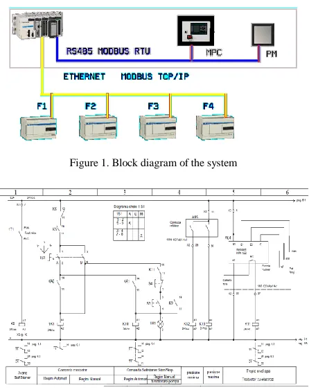
Four well pumps starters and corresponding water tank, located approximately 2 km from each other, were interconnected by a single-mode optical fiber line. Using Schneider Electric products, it was designed a flexible structure, easily reconfigurable, with monitoring and control facilities [6] – [9].
The hardware solution shown in Fig. 1 included: - Modicon M340 PLC – with I/O extension modules; - Magelis XBT GT – multifunction graphic terminal off XBT GT6330 touch screen type;
- Twido – programmable logic controllers of TWD LCDE40DRF type;
- Magelis XBT RT500 – Alphanumeric semi-graphical unit;
- PM710 – power monitoring unit;
- MPC – control panel of the Grundfos pumping group. Interfaces used: Ethernet & optical fiber, RS 485 and RS232.
Standards and communication protocols: Modbus RTU, Modbus TCP/IP, GSM/GPRS.
The presented system allows all the basic functions of the pumping station automation: surveillance, control and interlocking, sequential automatic management, change of adjustable parameters, alarms and event management, self diagnosis, communication with other systems.
Schematic and panel drawings presented in Fig.2 have been created in AutoCAD.
The simplified logic diagram shown in Fig. 3 was developed and drawn from initial information obtained from the operational description of a water well.
Figure 1. Block diagram of the system
Cristian PÎRVU, Costin CEPIŞCĂ
2
Figure 3. An example of logic diagrams
For each objective, it has considered the existence of operating modes such as manual mode or automatic mode with local control, useful at commissioning and maintenance, other than the normal working regime, the automatic-remote mode, depending on the water level and operating permission.
For electrical parameters monitoring and energy measurements has provided a Merlin Gerin PM700 power meter.
There are many sets of sensors: level switches and ultrasonic level transducers, with 4-20 mA analog output, to determine the presence of water in wells or degree of filling of the tank. In addition, there are flow meters, pressure gauges with contacts and a pressure transmitter, disposed on the discharge pipes at the each installation. The submersible pumps from the water wells line can operate independently of each other, by implementing the programmable controllers for command, control, protection and signaling.
The PLCs provided in electrical panel (Fig. 4) of the water wells ensure access to information via HMI while facilitating remote data transmission to higher-level control:
- discharged flow;
- circuit breaker / contactor / softstarter faults; - pump status (on / off);
- water level (minimum / maximum); - number of starts per day;
- pump operating time;
- monitoring supply voltage range in electrical panel; - lack of control voltage 24 Vdc;
- unauthorized door opening in well or electric panel;
System functions implemented al local level: - self diagnosis of the automatic system; - logics for start/stop commands; - emergency stop;
- display all process information on touch screen; - secure commands on desktop screens;
- alarming at exceeded periods, previously established intervals to stop pumping;
- Counting the number of pumping on the day; - Warning about the communication status between programmable controllers and HMI terminal;
- selecting manual/automatic mode,
- under local /remote control (software switch).
Figure 4. Automation and electrical panels
The central equipment, a data concentrator, was made with a Modicon M340 programmable controller that ensures the functioning of the whole system, depending on the water level in the reservoir and water consumption. Furthermore, it provides remote start/stop and setpoint commands for the pumping group equipped with inverter. It also acts as the communication master that polls all sites.
System functions implemented: - level measurement;
- upper and lower limit on the input or output signal (setpoint limits, according to operating mode) - software configurable level thresholds; - selecting manual/automatic mode;
- under local /remote control (software switch); - periodically rotate the switching order to equalize run hours;
- emergency stop;
- display all process information on touch screen; - secure commands on desktop screens;
- warning about communication status.
The whole functioning was first tested in the laboratory, under conditions simulating the real process (Fig. 5).
III. PLCSOFTWARE PACKAGE
Starting from automation graphs, the program for Twido PLCs has been implemented in Ladder language through the editor of the TwidoSuite programming environment from Telemecanique (Fig. 6). Previously were assigned input and output PLC variables and internal memory variables, of boolean, integer or real type, delay blocks, pulse counters.
Figure 6. TwidoSuite programming environment
Schneider-Electric Unity Pro is the software environment for designing and programming of the central programmable controller. It is an high performance multitask software, offered for the Modicon M340 and the Premium or Quantum PLC‘s.
An example of the Unity Pro application in design stage is presented in Fig. 7.
Figure 7. Unity Pro software package
Unity Pro makes the best use of the graphic and context-sensitive interfaces of Windows operating systems. It offers five IEC 61131-3 languages as standard. Each section of code can be programmed in the language of user’s choice, best adapted to each processing operation. All of the edit, debugging and operation tools are accessible whatever language is used. The main benefit is in a complete set of functions and tools enabling modeling of application structure on any machine or process structure. The program is split into organized function blocks by grouping: program sections, animation tables, operator screens and hyperlinks.
FBD (Function Block Diagram) editor is a program that allows viewing of the instructions through logical boxes, very similar with logic gates (AND OR NOT XOR, etc.) in digital electronics. There are no contacts or relays found in Ladder editor, but can be found equivalent
instructions that appear like boxes of instructions. The program logic is implemented through modes of connection between these boxes of instructions.
The FBD bistable function blocks (SR and RS) consist of two stable states controlled by one or more inputs. Starting from level 2 GRAPHCET of the application, the programs were made using bistable blocks of RS type, with reset dominant entry: Q n+1 = R . (S + Q n)
Variables are attached to graph stages, represented by the outputs of bistable blocks. The entries correspond to the activation functions of the stages, while the reset inputs are the steps to be activated when the current stage is disabled.
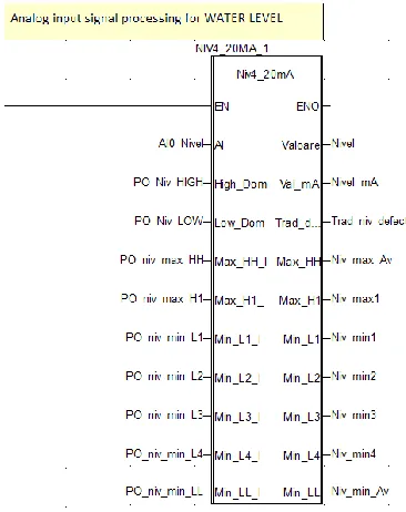
Repetitive used basic functions are encapsulated in user function blocks DFB (Derived Function Block) in IEC 61131-3 language. DFB types are function blocks that can be programmed by the user ST, IL, LD or FBD. The application uses a Level DFB (Fig.8), with level limits and thresholds, and a Flow/Pressure setpoint DFB.
Figure 8. Function block DFB
IV. COMMUNICATION PROTOCOL
Communicating via Modbus enables data exchange between all devices connected to the bus. The RS485 bus consists of one master station and several slave stations. Only the master station can initiate the exchange (direct communication between slave stations is not possible). The Modbus protocol is a communication protocol that creates a hierarchical structure. A master, in this case the PLC, addresses slave devices individually, the power monitoring unit and the control panel from the pumping group, then these devices return the reply to the requests.
Cristian PÎRVU, Costin CEPIŞCĂ
4
- RS 232 port 0: RS 232 8-wire, non-isolated - RS 485 port 0 and port 1: RS 485 2-wire, isolated Another serial link is between PLC and the operator panel. The BMX P34 2020 processors enable communication via a serial link. This processor has an integrated communication channel dedicated to serial communications. Master device is the Magelis console. Modbus protocol has been combined with Ethernet to form Modbus/TCP, a completely open Ethernet protocol. The main connection is the Ethernet network, with architecture consists of four Twido PLCs and the central PLC, via their integrated Ethernet ports, and is used to manage the exchange of remote I/O states on the Ethernet network after a configuration operation, with a special programming.
The application variables (tags) are available by Modbus TCP/IP protocol in Ethernet network, at fixed IP addresses. Modicon M340 station can exchange a maximum of 100 words for writing and 125 words for reading.
When is used as the master processor in a Modbus link, a BMX P34 2020 processor supports several services via the communication functions. Two specific functions are defined for sending and receiving data via a Modbus communication channel:
- READ_VAR: to read variables. - WRITE_VAR: to write variables.
The following Modbus requests are addressed to the slave device with which you wish to carry out reading or writing of variables:
Read bits 16#01 or 16#02 READ_VAR Read words 16#03 or 16#04 READ_VAR Write bits 16#0F WRITE_VAR
Write words 16#10 WRITE_VAR
These requests use the READ_VAR and WRITE_VAR communication functions.
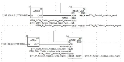
Figure 9. Communications functions in FBD
The diagram shown in Fig. 9 represents an example of programming of the communication functions in FBD for Modbus/TCP protocol.
The lines of code below represent an example of programming of the READ_VAR and WRITE_VAR communication functions in ST language for implementing the Modbus RTU:
READ_VAR(ADDM('0.4.1.2.MBS'), ’%MW’, 110, 20, Management_Table, Receiving_Table);
WRITE_VAR(ADDM('0.4.1.2.MBS'), ’%MW’, 150, 10, Data_to_write, Management_Table);
The syntax of the address of device on the bus is of the ‘r. m. c. node’ type. The address is made up of the following parameters:
r: Rack number of the module
m: Slot number of the module within the rack c: Channel number of the module
node: Number of slave to which the request is being sent.
The following table outlines the various parameters for the READ_VAR function [9]:
Table 1.Parameters description
Parameter Type Description
ADR ARRAY
[0..7] OF INT
Address of the destination entity given by the OUT parameter of the ADDM function.
OBJ STRING Type of object to be read. The available
types are as follows: %M: internal bit %MW: internal word %I: external input bit %IW: external input word
NUM DINT Address of first object to be read.
NB INT Number of consecutive objects to be read.
GEST ARRAY
[0..3] OF INT
Exchange management table consisting of the following words:
- Rank 1 word: A word managed by the system and consisting of two bytes: - Most significant byte: Exchange number, - Least significant byte: Activity bit (rank 0) and cancel bit (rank 1).
- Rank 2 word: a word managed by the system and consisting of two bytes: - Most significant byte: Operation report, - Least significant byte: Communication report.
- Rank 3 word: A word managed by the user which defines the maximum response time using a time base of 100 ms. - Rank 4 word: A word managed by the system which defines the length of the exchange.
RECP ARRAY
[n..m] OF INT
Word table containing the value of the objects reads.
The command system is provided with the possibility of connecting to a higher level of supervision of the plant, the SCADA system.
V. USER INTERFACE
Magelis operator dialogue terminals communicate with an automation system equipment.
Vijeo Designer HMI software [10] is a software tool that allows the creation of such HMI interface, the screens for touch panel TP. The setting for Magelis graphic terminal, XBT GT6330 type, with 12” screen, is processed offline. Use of TP requires the configuration of the controls by assigning of tags and functions that allow TP to interact with PLC programs.
Figure 10. Screen for pumping station
When is powered, TP has a default screen (Fig. 10). The main screen allows online monitoring of the pumping group and the reservoir.
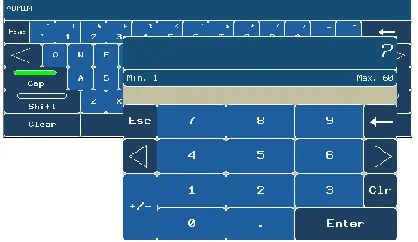
Each screen contains one or more controls, which are data indicators, numeric data entry, touch elements. The operator uses these elements to control or for parameterization (Fig. 11).
Figure 11. Numeric keypad (for parameterization) and alphanumeric keypad (login)
Images were placed on the screen to make a presentation or animation. We're also defined controls, navigation buttons, to load and display a separate screen when the button is pushed.
The operator monitors the real-time on/off status of the pumps, positions for switching elements or changes in operation (selector switches, contactors, circuit-breakers), being warned of the occurrence of events or alarms. The access to commands and settings are enabled only secured, through a password.
On the screen designated to control the water wells the interface elements are grouped into functional units (Fig. 12). The commands on/off can be transmitted in manual mode by the operator or in automatic mode depending on the water level in the tank.
Communication integrity is extremely important. All errors are reported.
Figure 12. Screen for remote control of the water wells
The list of alarms (Figure 13) displays alarm messages, but also additional information, date and time when an alarm activated, the time when the alarm was confirmed by the operator and is canceled when the condition of alarm generation. The messages change color depending on alarm status, active, confirmed or canceled alarm. Alarm display is done in the chronological order of the activation.
Figure 13. List of alarms and events
When analyzing the cause of process disturbances, the comparison of alarm and trend data (Fig. 14), an intuitive evolution, can be quite revealing.
There is a screen (Fig. 15) that allows monitoring of electrical parameters: line voltage, phase current, active and reactive power, energy consumption, frequency, power factor.
Cristian PÎRVU, Costin CEPIŞCĂ
6
Figure 14. Trends
Figure 15.Electrical parameters
Figure 16 . Windows for online management of user groups and for login procedure
Activation of Web Gate component allows the operator console to act as a Web Server, providing flexibility in accessing the system from remote sites as Web Client through a browser, either Internet Explorer or otherwise. Thus, data are displayed in real time; the operators can change the reference values and can give commands to the system. The access may be limited, based only on IP address, just a single PC, such as the control room. The access control is similar as for a console, based on an identical mechanism for identification and authentication, with username and password.
Vijeo Designer Lite configuration software allows creating operator dialog applications for Magelis XBT RT small panels for controlling local automation systems (Fig. 17).
Figure 17. Matrix display unit with keypad
VI. CONCLUSION
The article presents the design and programming stages and methods, both for the components and the entire system, focusing on the industrial communication system. The selected programmable controllers and operator terminals represent an optimal solution for automation of medium complexity applications. The compact design and a complex set of instructions make from this automation system a proper solution to control supplying water applications.
Presented system is an open system that allows further hardware and software development, both at operating and process stations and at communication system.
ACKNOLEDGEMENT
The work has been partially funded by Grant no.30_PCCA_2012 of the Romanian National Authority for Scientific Research CNDI– UEFISCDI.
REFERENCES
[1] Rafferty, K, Specification of Water Wells, ASHRAE Transactions, Vol. 107, Pt. 2., 2001
[2] Paradise:Water System Monitoring and Control, Campbell Scientific, See also: https://www.campbellsci.com/paradise-ut-water
[3] Water well drilling methods
See also: http://www.michigan.gov/documents
[4] Margineanu I., Automate programabile, Ed. Albastra, Cluj-Napoca, 2005
[5] Pirvu,C, Cepisca,C, Sisteme informatizate de măsurare, Ed.Electra, 2004, Bucuresti
[6] Twido programmable controllers, Software Reference Guide, Schneider-Electric
[7] Malvoisin,A.- Notice programmation d’automates Schneider Modicon, Premium, Quantum sous Unity Pro, See also: www.labase-malvoisin.net
[8] Unity Pro. Program Languages and Structure, Schneider Electric [9] Modicon M340. Using Unity Pro S. Architectures and