Guest Editors: Judy Bowen, Steve Reeves
Proceedings of the
5
thInternational Workshop on
Formal Methods for Interactive Systems
(FMIS 2013)
Analysis of WIMP and Post WIMP Interactive Systems based on
Formal Specification
J. L. Silva1, C. Fayollas1, A. Hamon1, P. Palanque1, C. Martinie1, E. Barboni1
Analysis of WIMP and Post WIMP Interactive Systems based on
Formal Specification
J. L. Silva
1, C. Fayollas
1, A. Hamon
1, P. Palanque
1, C. Martinie
1, E. Barboni
11IRIT, Université Paul Sabatier, 118, route de Narbonne
31062 Toulouse Cedex 9, France
{silva, fayollas, hamon, palanque, martinie, barboni}@irit.fr
Abstract: While designing interactive software, the use of a formal specification technique is of great help by providing non-ambiguous, complete and concise descriptions. The advantages of using such a formalism is widened if it is provided by formal analysis techniques that allow to prove properties about the design, thus giving an early verification to the designer before the application is actually implemented. This paper presents how models built using the Interactive Cooperative Objects formalism (ICOs) are amenable to formal verification. The emphasis is on the behavioral part of the description of the interactive systems and more precisely on the properties at the interaction technique level. However, the process and the associated tools can be generalized to the other parts of the interactive systems (including the non-interactive parts).
Keywords: Formal methods, interactive systems, object oriented Petri nets, colored Petri nets, Analysis.
1
Introduction
The paper makes two contributions:
It introduces an analysis technique for ICO-based interactive systems that is independent of the interaction technique;
It shows that this analysis based on property patterns is an adequate approach for the verification of properties of interactive systems.
The next section of the paper presents an overview of the state of the art of interactive systems engineering approaches providing analysis support. The paper then moves from the description of the proposed approach to the analysis results demonstrated through application examples.
2
Background
Currently the vast majority of approaches used to develop different interaction techniques are tackled by the use of usual programming languages. The use of programming languages poses some advantages when compared to the use of models but also disadvantages such as reduced analysis support. In fact the approaches addressing the analysis of source code (e.g. static and dynamic program analysis) are limited to the analysis of reduced subsets of the language. Additionally some techniques need the creation of models from the source code. The analysis of programming languages using static program analysis are commonly presented as fast and inaccurate [26]. Alternatively the use of dynamic program analysis must be executed with sufficient test inputs to produce interesting results [26]. The development of interaction techniques based on models provides by itself an advantage in terms of analysis support. Some approaches based on models providing analysis support are presented. The IVY tool [8] enables systematic analysis of properties of interactive behavior using Modal Action Logic (MAL) and the SMV model checker [17]. Marigold [27] addresses limited validation and verification analysis of interactive systems based on reachability graph analysis. The analysis addresses only properties concerning correctness (i.e. safety, liveness and mode confusion). However to reduce this limitation Marigold has the ability to export the specification to a file format loadable by the integrated net analyser tool [21] offering other analysis facilities. Proton++ [14] enables the modeling of post-WIMP interfaces but only provides static analysis support in terms of gesture conflict detection between models. The VEG (Visual Event Grammars) specification based on grammars [7] enable, with the model checker Spin [9], the verification of properties and the detection of deadlocks and unreachable states. ICO [19] provides support for validation and verification but only through invariant analysis (Place/Transition invariants) provided by the Petshop tool. Finally, colored Petri nets (CPN) is the more complete approach in terms of analysis enabling validation, verification and performance analysis accomplished by all the different types of analysis techniques except invariant. The analysis of CPN models is supported by the CPN Tools [12].
Recent advances identified the lack of a formal description technique that adequately provides executable models and expressive power to deal with the formal specification of different interactive systems (e.g. ICO) and providing adequate analysis supports (e.g. CPN Tools). Martinie et al. [16] introduced an approach to reduce this gap converting ICO models into CPN models. Based on this advance, this paper shows the CPN analysis benefits provided to the development of ICO-based interactive systems. This goes beyond previous work we did on property verification which were only based on basic Petri nets [20].
3
WIMP and Post-WIMP Examples
paradigms and their associated HMIs (Human-Machines Interfaces) are defined as GUIs composed of widgets, graphical components that allow the user to trigger systems commands while manipulating them. A complete description of this interaction paradigm can be found in [6]. From this definition, every interaction technique which enriches the WIMP paradigm is thus tagged as post-WIMP ([22]).
As this paper context lies with critical embedded systems, and interactive cockpits in particular, the following examples will illustrate the case studies supporting our research. On one hand, we intend to target actual CDS (Control and Display Systems) while on the other hand we evaluate our specification/analysis capabilities with regards to future HMI concepts for more integrated interactive cockpits.
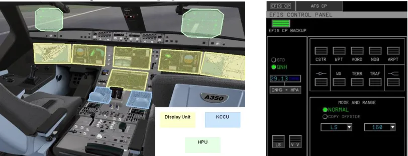
The actual CDS is the interactive system in the cockpit. It allows the display of aircraft parameters on output devices called Display Units but it also allows the pilots to interact with these parameters, using devices called KCCUs (Keyboard Cursor Control Units) gathering a keyboard and a mouse for each pilot. Pilots-CDS interactions are based on the WIMP paradigm and mostly rely on the KCCUs input modality. Figure 1 presents an aircraft cockpit together with a screen shot of an interactive application: a part of the Flight Control Unit Backup responsible for the back-up of the configuration of navigation displays and the settings of the autopilot state and parameters. For sake of safety, the WIMP paradigm has been studied and standardized to be used in aircraft cockpits [3].We also proposed a mechanism to secure these interactive components in order to extend their use in the cockpits towards more critical HMIs which extends previous work [25].
Figure 1 - Example of an aircraft cockpit and screen shot (left) of a WIMP aircraft application (right)
This paper aims at conciliate these new interaction paradigms with the usability and reliability they need to provide to enter newest cockpits. For this demonstration purpose, we consider a multi-touch display providing pilots with a navigation application. This application enables multi-touch interactions such as Pinch for zooming (presented in Figure 7), 2-Fingers rotations, etc.
4
Generic Process Analysis
The Petri net formalism enables the use of several analysis capabilities. This set of capabilities is divided into three groups addressed by different types of analysis techniques:
validation, accomplished by interactive simulation (step by step), invariant, structural and reachability graph analysis;
verification, accomplished by invariant, structural and reachability graph analysis;
performance analysis, accomplished by simulation and by computation of performance according to quantitative information such as time [15].
Model based analysis techniques concerned with the validation and verification are considered in this paper. In particular the focus is on invariant, structural and reachability graph analysis. This section describes the tool support and analysis process.
Tool support and Process
To achieve the analysis of the formal description of interactive systems based on ICO models the Petshop [4] and CPN tools [11] are used. Petshop, the tool supporting the ICO notation, is used to perform the invariant analysis while the CPN Tools is used to accomplish the structural analysis and reachability graph analysis. The expressive power of ICO notation is higher than the one of CPN meaning that tools supporting analysis of CPN models are not directly applicable. There is thus a need to convert ICO models to CPN to accomplish the analysis using the associated tools (i.e. CPN tools). The translation from ICO models to CPN models means that some information is lost. However, for analysis purpose those simplifications have no negative implications since the features used for the analysis (e.g. behavior) remains present in the translated model, i.e. bugs in ICO models are also bugs in CPN models and vice versa. The description of the translation process is not described here as it is out of the scope of this paper (see [16] for a description of this process). The focus here is to demonstrate that the various analysis that can be performed on CPN models are useful to assess interactive systems modeled in ICO. The analysis process accomplished is divided in two parts:
Synchronous - accomplished while creating the ICO models. It is achieved using the Petshop and enables invariant analysis;
Asynchronous - accomplished after the creation of the ICO models (previously converted into CPN models) using CPN Tools for performing structural analysis and reachability analysis based on the creation and analysis of the corresponding reachability graph.
from one state to a new one. Figure 2 illustrates part of one of these graphs. The whole graph represents all possible executions of a system showing which actions can be executed in each system state. Each node is numbered and labeled with its number of input/output arcs. Arc and node labels are hidden by default in the tool, but can be checked interactively. Figure 2 shows the arc caption 3 from state 1 to 4 (in the top) and part of the node 1 content (right hand side). Provided queries together with CPN ML code (an extension of the functional programming language Standard ML) are used to write specific queries about the CPN models, for example to demonstrate that the system always works as expected. The returned result is either that the query is true of all relevant states or that the query fails to be true, in which case the path to the failing state is deduced. This path can then be used to explore situations that may be of interest from the perspective of the design of the system. More details about these tools are contained in the CPN tools State Space manual [10]. Additionally, properties based on patterns can be of interest. Silva et al. [23] proposes a set of algorithms for the identification and verification of properties that are generic for different systems (e.g. consistency, reachability and precedence). The pattern defines an algorithm skeleton describing how the reachability graph is to be explored (which queries are needed) to perform the verification. These algorithms are instantiated in order to accomplish the analysis for a particular example. More details about how these algorithms are instantiated and verified are described in [23].
A description of each analysis technique for validation and verification are presented in the following sub-sections.
Figure 2 –Reachability graph
Invariant Analysis
The Invariant analysis is used to avoid state-explosion problem and poor diagnostics. The properties are independent of initial state and can be computed using linear algebraic techniques. The invariant analysis is divided into two types:
Place invariant (P-invariant) - provides support for verifying that some places will always contain a token (i.e. no token loss). This means that whatever states the model is in, and whatever events are produced, these places will never lose their resources i.e. the number of tokens set in these places at the initial state remains unchanged.
Transition invariant (T-invariant) - provides support for demonstrating liveness of transitions. For example, it provides support for ensuring that the user will always be able to perform a particular action or that at least one action will always be available for the user.
Structural Analysis
Using this analysis technique several properties can be verified such as:
Home properties - determines whether the marking of the specified node is a home marking, i.e., whether it can be reached from all reachable markings. This property is
3:1->4 transducer'rawtouchEventDown 1: {f={id=1,posX=0,posY=0,timeSt=0}}
4 1:5 3 1:5 7 2:7 12 1:3 11 2:7 6 2:7 14 1:4 15 1:3 16 1:5 13 1:5 10 1:4 2 1:5 1 0:3 1:
transducer'fingerPool 1: 1`{id=1,posX=0,posY=0,timeSt=0}++ 1`{id=2,posX=0,posY=0,timeSt=0}++
1`{id=3,posX=0,posY=0,timeSt=0} transducer'Pressing 1: empty transducer'EVTdown 1: empty transducer'EVTup 1: empty transducer'EVTmove 1: empty pinch'nbFingerInModel 1: empty pinch'p1 1: empty
pinch'p2 1: empty pinch'temp 1: empty pinch'EVTdown 1: empty pinch'EVTup 1: empty pinch'Pressing 1: empty pinch'EVTmove 1: empty 1:
transducer'fingerPool 1: 1`{id=1,posX=0,posY=0,timeSt=0}++ 1`{id=2,posX=0,posY=0,timeSt=0}++
1`{id=3,posX=0,posY=0,timeSt=0} transducer'Pressing 1: empty transducer'EVTdown 1: empty transducer'EVTup 1: empty transducer'EVTmove 1: empty pinch'nbFingerInModel 1: empty pinch'p1 1: empty
the basis for demonstrating that a model is reinitializable (an important feature of critical systems);
Liveness properties - a net is live, if all its transitions are live in the initial marking, i.e., no state is reachable in which a transition is dead (deadlock-freedom) [24];
Fairness properties - a transition t is fair if t occurs infinitely often in every Infinite Firing Sequences where t is enabled infinitely often [24]. This property is important to ensure that no transition is delayed indefinitely.
Reachability Graph Analysis
As stated, this analysis technique enables the verification of generic properties based on patterns (e.g. consistency) and specific properties only valid in a specific example.
5
Application to Interaction Techniques
This section describes the analysis accomplished following the stated approach on two interactive systems formally described in Petshop. ICO models and some of the corresponding CPN models obtained after the translation as well as analysis results are presented.
Examples focus on the description of two different interaction techniques (WIMP and post-WIMP) by describing how raw events coming from the input devices are transformed into higher-level events used by graphical components. For each interaction technique two models at different levels of abstraction (low-level and higher-level) are presented.
Figure 3 – ICO mouse transducer model
WIMP Interactive System
In precedent work [19], we show how to describe every part of the interactive system from the interaction technique to the application behavior. In this paper, we consider the example of mouse interaction on a PushButton. For the post-WIMP interaction, we introduce in this paper two levels of the interaction technique, (i) the low-level transducer model that describes how raw events coming from the input device are translated into higher-level events and (ii) the
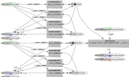
Figure 4 presents an excerpt of the behavior of a PushButton. It presents the inner state of the
PushButton as Visible (token in place Visible) and Enabled (token in place Enabled). This inner state allows the widget to produce the widget-level event A661_EVT_SELECTION upon a mouse click: when the widget receives a higher-level event click from the mouse transducer (token in place SIP_processMouseClicked), it raises the A661_EVT_SELECTION if its inner state is Visible and Enable. A synchronized transition of an hidden part of the PushButton
model is responsible to put a token in the SIP_processMouseClicked place when the click
event is received. This property is also an important one to verify, the event
A661_EVT_SELECTION cannot not be send if the widget is not visible and enabled. Places
Visible and NotVisible (resp. Enabled and NotEnabled) represent the visibility (resp. activation) state of the widget, they must be in mutual exclusion, indeed, the widget cannot be both Visible and NotVisible (resp. Enabled and NotEnabled).
Figure 4 – Extract of ICO PushButton model
Analysis Results
The invariant analysis results indicated the presence of P-invariants and T-invariants. For example the PushButton model contains two P-invariants, one with the places Visible and
NotVisible and the other with the places Enabled and NotEnabled. Whatever states the model is in, and whatever events are produced, the number of tokens set in these places at the initial state remains unchanged. As the initial number of tokens is one this means that the button states Visible and NotVisible are in mutual exclusion as desired. The same is verified for the states Enabled and NotEnabled.
Considering the structural analysis some dead markings were identified due to the use of a partial reachability graph. In respect to fairness, all transitions are impartial.
the PushButton model the verification of the non-existence of a state where a selection is accomplished (execution of the transition Selection – Figure 4) without the reception of a mouse click (token into the SIP_processMouseClicked place) and without the button being visible and enabled was verified. This property was verified instantiating the same precedence property algorithm. The resulting instantiation is presented in Figure 5 (instantiated values of the CPN model are underlined). This concrete algorithm identifies those nodes where the button is not visible and not enabled (originalNodes) and the nodes (targetNodes) when the event A661_EVT_SELECTION was triggered (state mouseClicked1 – Figure 5). After the identification of these nodes the algorithm identifies counter examples (i.e. nodes) hold in the variable PRECEDENCE where the event is sent and the button is not visible or not enabled. The resulting list of nodes is empty. This means that for the analyzed scenario there is no system execution containing a node where the event A661_EVT_SELECTION was triggered while the button being invisible or disabled.
Figure 5 - Instantiated precedence pattern algorithm
A more detailed description of the analysis made is presented using the post-WIMP example.
Post-WIMP Interactive System
The low level transducer model is the one linked to the hardware touch events. An excerpt of this model is presented Figure 6. It parses the features of the received event into a java finger object. The FingerPool place acts as a limiter on the allowed number of distinct fingers input. This transducer packages events, forwards them to models listeners (i.e. higher-level events handlers) such as the Pinch (Figure 7) or the TapAndHold… as defined in [1]. Indeed, a
toucheventf_move or toucheventf_up event will only be triggered if the event corresponds to a registered finger.
Figure 6 – ICO low level event transducer model
Figure 7 – ICO pinch interaction model
In this configuration, two low level events may be handled:
toucheventf_down: another toucheventf_down received event behaves the same way on the PetriNet. Then if two tokens are stored in the p1 place, the eagerFusion transition is automatically crossed, grouping both fingers into the same token in place p2.
toucheventf_up: as long at the transducer contains information about at least one finger, the event handler toucheventf_up_1 is fireable. Each time such an event is received, a token containing the corresponding finger information is added to temp
place, leading to two cases:
o The toucheventf_up event corresponds to a finger stored in place p1: the transition endInteraction1 is fired, removing the finger’s related token in p1
and temp as well as one token from nbFingerModel place.
o The toucheventf_up event corresponds to a finger stored in place p2: the transition endInteraction2 is fired, subtracting the finger’s related token in p2
and temp; and two tokens from nbFingerModel place since to fingers are composing tokens in place p2.
The corresponding CPN models obtained following the translation proposed by Martinie et al. [16] are presented in Figure 8 and Figure 9. Their main differences are the usage of fusion places (e.g. EVTmove or EVTdown places) to represent the trigger of events in the ICO models. Others differences are present, however, the behavior remains present enabling the analysis using CPN tools without losing relevant information.
Figure 8 - CPN translated low level event transducer model
Analysis Results
The analysis results for this example are divided into the stated three analysis techniques (i.e. invariant, structural and reachability graph analysis). Analyzing the low level event transducer
model (Figure 8) invariants were identified. The net is covered by P-invariants therefore there is no token loss. Additionally, the net is covered by T-invariant, therefore all transitions are live. For the designer/developer this means that there are no dead branches in the specification.
Figure 9 – CPN translated pinch interaction model
() () () f f f update(f) f f touchEventMove rawtouchEventUp rawtouchEventDown EVTmove move EVT EVTup up EVT EVTdown down EVT Pressing Pressing FINGER fingerPool 1`{id=1,posX=0,posY=0,timeSt=0}++ 1`{id=2,posX=0,posY=0,timeSt=0}++ 1`{id=3,posX=0,posY=0,timeSt=0} FINGER Pressing down up move () f () () f f f f f3 f f f (f1,f2) (f1,f2) (f1,f2) f1 f2 f toucheventf_down toucheventf_up endInteraction2 [(#id f = #id f3)]
Considering the pinch interaction transducer model (Figure 9) together with the low level event transducer model (Figure 8) the following structural analysis results were identified:
Home property - no home marking (see home property definition in section 4);
Liveness properties - Some dead marking were identified because the generated reachability graph was partial;
Fairness properties - no infinite occurrence sequences were identified meaning that all transitions are impartial.
This analysis was made considering both models together because if analyzed separately wrong conclusions can be obtained. For example, analyzing the pinch interaction transducer
model (Figure 7) separately we can conclude that it is possible to execute the
toucheventf_down_1 transition for a finger several times without triggering any finger up event for this finger. This is not true because models work together and this situation never occurs because it is restricted by the low level event transducer model.
To illustrate the reachability graph analysis technique the results of two properties based on the stated example are presented:
For each finger the UP and MOVE events cannot occur without being preceded by a DOWN event.
A pinch cannot be completed without the occurrence of an UP event.
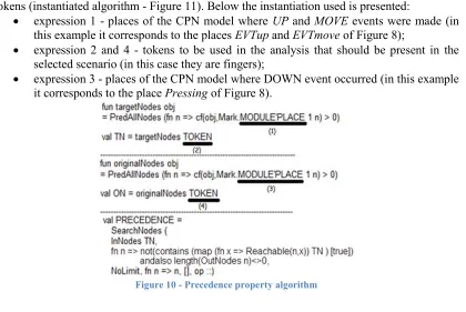
The first property is verified using one of the algorithms based on property patterns provided by Silva et al. [23] (precedence - see Figure 10). The verification is made by instantiating the algorithm with adequate values relative to this example. The instantiated algorithm consists in firstly identifying the nodes where events UP or MOVE were made and secondly analyzing their predecessors to check the absence of a node where the event DOWN occurred. Nodes correspond to states of the reachability graph. The return of zero nodes means that for the selected scenario the property is always true. The instantiation of the property is made by substituting the underlined expressions of the algorithm (see Figure 10) by relevant places and tokens (instantiated algorithm - Figure 11). Below the instantiation used is presented:
expression 1 - places of the CPN model where UP and MOVE events were made (in this example it corresponds to the places EVTup and EVTmove of Figure 8);
expression 2 and 4 - tokens to be used in the analysis that should be present in the selected scenario (in this case they are fingers);
expression 3 - places of the CPN model where DOWN event occurred (in this example it corresponds to the place Pressing of Figure 8).
After being instantiated the algorithm checks the predecessors of the target nodes to check the presence of counter examples, which means in this case, the identification of nodes that are not present in the set of original nodes (hold in the PRECEDENCE variable). This situation, if exists, means that there are situations where for a finger a DOWN event was not made before an UP or MOVE event. For the selected scenario (3 fingers and can be extended to n fingers) the result returned means that the property is always true (zero nodes in the variable
PRECEDENCE).
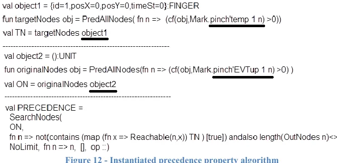
Figure 11 – Instantiated precedence property algorithm
The second property is verified following the same reasoning. The functions of the algorithm are used to identify, in the reachability graph, counter examples (i.e. a pinch being completed without the occurrence of a UP event) by the identification of relevant nodes. The algorithm (Figure 12) is applied to the selected scenario and the resulting list of nodes (hold in the PRECEDENCE variable - Figure 12) indicates if the property holds. In this example, for the selected scenario (i.e. 3 fingers), counter examples were not identified. More properties can be analyzed by instantiating this or other provided algorithms or alternatively developing new ones. Counter examples identified when properties are not verified provide an important aid to the redesign process.
It is important to emphasize the fact that the invariant analysis can be made to models separately, however, the structural analysis and reachability graph analysis must be done joining all models to avoid wrong analysis results.
6
Conclusion
This paper introduces a method for evaluating interactive systems formally described using ICO models through exhaustive analysis, applying an approach based on property patterns. Both WIMP and post-WIMP interactive techniques were analyzed demonstrating that the approach is independent of the interaction technique. Furthermore, it was demonstrated that the approach enables developers to validate and verify the interaction techniques they are developing (e.g. fault detection) playing an important role in the development process. The analysis support provided is complete and provides an improvement when compared with the isolated use of Petshop. Additionally, analysis results can be fruitfully re-injected in the design process improving the interactive system.
ICO models aims to be used for the formal description of interactive systems addressing usability, reliability and scalability while being able to describe various aspects of user interfaces namely different interaction techniques (e.g. multimodal, WIMP, post-WIMP), interactive components (e.g. widgets), the dialogue and the functional core [19]. This paper presented a generic approach to analysis ICO specifications that was missing. Results demonstrated that the approach enables the identification of several analysis results completing the currently limited analysis support provided by Petshop.
Even though the current analysis is mainly based on behavioral properties, current work on ICOs aims at integrating behavioral descriptions with graphical representation [4]. This will make it possible to verify properties on the graphical part of the interactive system such as objects’ overlapping, color’s matching, … and integration of behavioral and graphical aspects.
Acknowledgements
This work is partly funded by Airbus under the contract CIFRE PBO D08028747-788/2008 and R&T CNES (National Space Studies Center) Tortuga R-S08/BS-0003-029. Special thanks to Yannick Deleris for his support.
References
1. Accot J., Chatty S., Maury S. and Palanque P. Formal Transducers: Models of Devices and Building Bricks for Highly Interactive Systems DSVIS, Springer, pp. 234-259. 1997. 2. Apple Corp. iOS Human Interface Guidelines.
http://developer.apple.com/library/ios/#documentation/UserExperience/Conceptual/Mobile HIG. Date of Access: 04/03/2011.
3. ARINC 661 Cockpit Display System Interfaces to User Systems. ARINC Specification 661. Airlines Electronic Engineering Committee 2002.
4. Barboni E., Martinie C., Navarre D., Palanque P. & Winckler M. Bridging the Gap between a Behavioural Formal Description Technique and User Interface Description Language: Enhancing ICO with a Graphical User Interface Markup Language. Science of Computer Programming Journal, 2013.
5. Bastide, R., Navarre, D. & Palanque, P. A model-based tool for interactive. prototyping of highly interactive applications. CHI '02., demonstration, ACM, 516-517. 2002.
6. Beaudouin-Lafon M. Instrumental interaction: an interaction model for designing post-WIMP user interfaces. Proceedings of the CHI’00 conference. 2000.
8. Campos J. & Harrison M. Systematic analysis of control panel interfaces using formal tools. DSVIS’08. Springer LNCS 5136, pp. 72–85.Springer-Verlag, 2008.
9. Holzmann G. The SPIN Model Checker, Primer and Reference Manual. Addison Wesley, 2003.
10. Jensen K. & Christensen S. CPN Tools State Space Manual. Aarhus Univ., pp. 1-49. 2006. 11. Jensen K., Kristensen L. M., & Wells, L. Coloured Petri Nets and CPN Tools for
modelling and validation of concurrent systems. International Journal on Software Tools for Technology Transfer, 9(3-4), 213-254. 2007.
12. Jensen K., Kristensen L. M., & Wells, L. Coloured Petri Nets and CPN Tools for modelling and validation of concurrent systems. Intern. Journ. on Software Tools for Technology Transfer, 9(3-4), 213-254. 2007.
13. Katsurada, K., Nakamura Y., Yamada H., and Nitta T. XISL: A language for describing multimodal interaction scenarios. In Proc. of the 5th Int. Conf. on Multimodal Interfaces (ICMI’03). ACM, N-Y, 281–284. 2003.
14. Kin K., Hartmann B., DeRose T., and Agrawala M. Proton++: a customizable declarative multitouch framework. In Proc. of the 25th annual ACM Symp. on User Interface Software and Technology (UIST '12). ACM, 477-486. 2012.
15. Lacaze X., Palanque P., Navarre D., Bastide R.: Performance Evaluation as a Tool for Quantitative Assessment of Complexity of Interactive Systems. LNCS, 208-222. 2002 16. Martinie C., PalanqueP., Silva J.L., NavarreD. Properties verification of interactive
systems by tool-supported analysis of its formal specification. Diffusion scientifique. April 2013. Available at:
www.irit.fr/~Celia.Martinie-De-Almeida/Technical_report_on_properties_verification_April_2013.pdf
17. McMillan, K. L. Symbolic Model Checking, Kluwer Academic Publishers. 1993.
18. Microsoft Corporation. Microsoft Surface User Experience Guidelines. Available on MSDNAA. 2009.
19. Navarre D., Palanque P., Ladry J-F., & Barboni E. ICOs: A model-based user interface description technique dedicated to interactive systems addressing usability, reliability and scalability. ACM Trans. Comput.-Hum. Interact. 16, 4, Article 18 , 56 pages. 2009.
20. Palanque P. & Bastide R.: Verification of an interactive software by analysis of its formal specification. INTERACT 1995: 191-196
21. Roch, S. and P. H. Starke . INA Integrated Net Analyser. Humboldt-Univ. Berlin. 1999. 22. Shneiderman B. 1981. Direct manipulation: A step beyond programming languages
(abstract only). SIGSOC Bull. 13, 2-3 (May 1981), 143. 2000.
23. Silva J.L., Campos J.C. , & Harrison M. D., Formal Analysis of Ubiquitous Computing Environments through the APEX Framework. EICS’12: ACM DL, pp. 131-140. 2012. 24. Starke, Peter H.: Analyse von Petri-Netz-Modellen. Stuttgart : B. G. Teubner, (Leitfäden
und Monographien der Informatik).1990.
25. Tankeu-Choitat A., Fabre J-C., Palanque P., Navarre D. & Deleris Y. Self-Checking Components for Dependable Interactive Cockpits. 13th European Workshop on Dependable Computing EDCC, ACM DL. 2011.
26. Vorobyov, K. & Krishnan, P. Comparing model checking and static program analysis: A case study in error detection approaches. 5th int. workshop on Systems Software Verification. 2010.