© Science and Education Publishing DOI:10.12691/wmt-2-1-1
An Improved Compact & Multiband Fractal Antenna
Using the Koch Curve Geometry
Manas Ranjan Jena1,*, B.B. Mangaraj1, Rajiv Pathak2
1
Deparment of ELTCE, VSSUT, Burla, Odisha, India
2
BIT, Durg, Chhatisgadh, India
*Corresponding author: [email protected]
Received March 26, 2014; Revised May 30, 2014; Accepted June 02, 2014
Abstract
In this paper, we have achieved an compact & multiband fractal antenna using a Koch curve geometry. The simulation of the proposed antenna is done by CST Microwave Studio EM simulation software. The proposed Koch curve fractal antenna proves that it is capable to create multiband frequencies. The proposed fractal antenna is designed on FR-4 substrate with ℇr= 4.4. The antenna is fed with the probe feed method. We got two resonant frequencies like 32.84GHz & 34.28GHz which shows multiband characteristics. Simulated results shows that the return loss is better than 15 dB, the VSWR is less than 1.3, the directivity is greater than 6dBi & the gain is more than 6dB in each band. So this fractal antenna can be suitable for the radio astronomy & space research applications.Keywords
: fractal antenna, koch curve, CST, IFS, self similarity, self filling, multibandCite This Article:
Manas Ranjan Jena, B.B. Mangaraj, and Rajiv Pathak, “An Improved Compact & Multiband Fractal Antenna Using the Koch Curve Geometry.” Wireless and Mobile Technologies, vol. 2, no. 1 (2014): 1-6. doi: 10.12691/wmt-2-1-1.1. Introduction
Now-a-days there is a need for more compact and portable communication systems. We know that antenna is an integral part of all the communication systems. So there is a demand for small antennas for portable communication systems [1].
It is well known that the antenna dimension is a function of its operating wavelength (λ). i.e if the antenna size is less than the operating wavelength (λ), the antenna becomes inefficient as its characteristics like radiation resistance, directivity, gain & bandwidth are diminished
[2]. Fractal geometry is a very good solution for this problem due to its two major characteristics like self similarity & space filling. so fractal geometry has become
an
important approach for designing multiband antennas[3,4].
A fractal is a rough or fragmented that can be sub-divided into parts, each of which is a reduced copy of whole. Therefore the basic property of a fractal shape is self similarity and structure at all scales [5].
The goal of this paper is to design and characterize a fractal antenna with Koch curve geometry as it has the potential to provide multiband solution [6].
A koch curve is a famous fractal objects in mathematics
[7]. These are low profile antennas with better return loss, VSWR, directivity and gain. So Koch curve can be made operative at multiple frequency bands and hence are multi-functional [8,9].
2. Antenna Design
2 0 2 0 2 0 2 0 0 0 0 0 0 90 120
( 2 )
( 2 )
eff
slot
in slot
slot w
G for W
w
G for W
k l B
z
Y jY tan L l
Y Y Y
Y jY tan L l
(
)
01/2
( 2 )
2 2 1 not critical 2 2 g eff r r L l c W f λ λ ε ε − + ∆ = = + =
Here we have designed a 3 GHz antenna using the following parameters.
Substrate: FR4 (εr= 4.4, h=1.6 mm).
0 1/2 1/2 2 2 0 10 1 6 2 2
1 1 12 (1 ) 2 2
0.3 0.264 0.412 ( )( ) 0.04
0.258
0.8 – 2 6
2 1 1 2 45 288 .5 2 0 12 1 0 . 4 r r r r r eff eff eff eff in in in OT in c cm f c W mm f h W W h
l h cm
W h c
L l mm
W
Y G
R
R input impendance
Z R λ ε ε ε ε ε ε ε λ − − = = + = = + − = + + + + = = − + = ∆ = = = =
= Ω =
= Ω
=
=
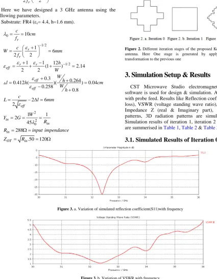
which the length of each side is 6 mm. Iteration 1 is produced by replacing each straight wire with the proposed generator shape as shown in figure 2b. Iteration 2 is produced from iteration 1 by using IFS (Iterated Function System) as shown in figure 2c [10,11].
Figure 2. Different iteration stages of the proposed Koch curve fractal antenna. Here One stage is generated by applying the affine transformation to the previous one
3. Simulation Setup & Results
CST Microwave Studio electromagnetic simulator software is used for design & simulation. Antenna is fed with probe feed. Results like Reflection coefficient (return loss), VSWR (voltage standing wave ratio), Variation of Impedance Z (real & Imaginary part), 2D radiation patterns, 3D radiation patterns are simulated [12,13]. Simulation results of iteration 1, iteration 2 & iteration 3 are summerised in Table 1, Table 2 & Table 3 respectively.
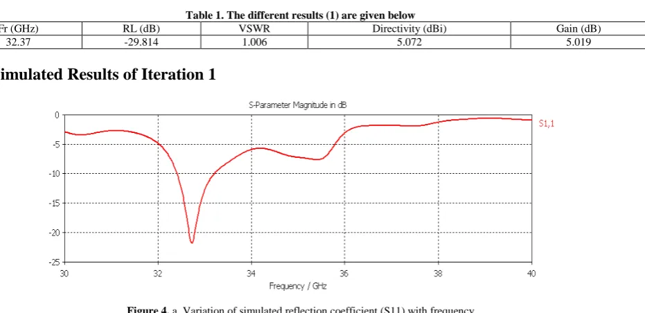
3.1. Simulated Results of Iteration 0
Figure 3. a. Variation of simulated reflection coefficient(S11)with frequency
Figure 3. c. 3D Radiation pattern (Directivity) at Fr=32.37 GHz
Figure 3. D. 3D Radiation pattern (Gain) at Fr=32.37 GHz
Table 1. The different results (1) are given below
Fr (GHz) RL (dB) VSWR Directivity (dBi) Gain (dB)
32.37 -29.814 1.006 5.072 5.019
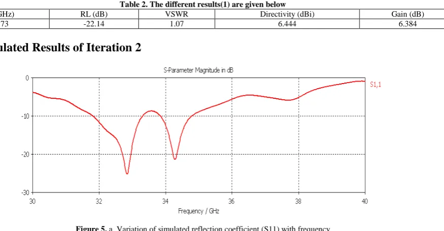
3.2. Simulated Results of Iteration 1
Figure 4. a. Variation of simulated reflection coefficient (S11) with frequency
Figure 4. c: 3D Radiation pattern (Directivity) at Fr=32.73 GHz
Figure 4. d. 3D Radiation pattern (Gain) at Fr=32.73 GHz
Table 2. The different results(1) are given below
Fr (GHz) RL (dB) VSWR Directivity (dBi) Gain (dB)
32.73 -22.14 1.07 6.444 6.384
3.3. Simulated Results of Iteration 2
Figure 5. a. Variation of simulated reflection coefficient (S11) with frequency
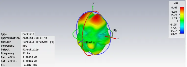
Figure 5. c. 3D Radiation pattern(Directivity) at Fr=32.84 GHz
Figure 5. d. 3D Radiation pattern(Gain) at Fr=32.84 GHz
Figure 5. e. 3D Radiation pattern(Directivity) at Fr=34.28 GHz
Figure 5. F. 3D Radiation pattern (Gain) at Fr=34.28 GHz
Table 3. The different results (9) are given below
Fr (GHz) RL (dB) VSWR Directivity (dBi) Gain (dB)
32.84 -25.1 1.1 6.087 6.115
34.28 -21.14 1.2 4.698 4.746
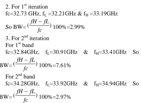
BW Calculation
1. For 0th iteration
fc=32.37 GHz, fL=31.67GHz & fH=33.83GHz
So BW=(fH fL)
fc
−
For 2 band
fc=34.28GHz, fL=33.92GHz & fH=34.94GHz So
BW=(fH fL)
fc
−
100%=2.97%
Table 4. Comparision of different major parameters for multiple iterations
Multiple Parameters 0th iteration 1st iteration 2nd iteration
Return loss -29.814 -22.14 -25.1
-21.14
VSWR 1.006 1.07 1.1
1.2
Directivity 5.072 6.444 6.087
4.698
Gain 5.019 6.384 6.115 4.746
Presence of multiband Nil Nil Yes (2)
BWenhancement 6.67% 2.99% 7.61%
2.97%
4. Conclusion
A fractal antenna with Koch curve geometry is designed & characterized. The simulated results show that return loss is more than -15 dB, VSWR is less than 1.3, directivity is more than 6dBi, gain is more than 6dB. This antenna not only improve return loss, VSWR, directivity & gain, but also can Provide a compact size of radiating patch. Gain is enhanced with multiple iterations. Bandwidth enhancements for multiple iterations is compared. Antenna size is reduced by using fractal shapes with multiple iterations. After these comparisons, it is clear that the proposed fractal antenna is superior than the conventional rectangular patch antenna. It follows the multiband characteristics which enables to use a single antenna instead of many. So the proposed antenna is
References
[1] Balanis, Constantine, “Antenna theory-Analysis and Design”, John Wiley & Sons Ltd, Reprinted 2008.
[2] B. B. Mandelbrot, “The Fractal Geometry of Nature” San Francisco, CA: Freeman, 1983.
[3] N. Cohen, “Fractal Antenna Application In Wireless Telecommunications” Proceedings of Electronics Industries Forum of New England, 1997, pp. 43-49.
[4] R.M. Crownover, “Introduction to Fractals and Chaos, Boston”, MA Jones & Bartlett, 1995.
[5] D. H. Werner, P. L. Werner, and K. H. Church, “Genetically engineered multi-band fractal antennas,” Electron. Lett., vol. 37, no. 19, pp. 1150-1151, Sep. 2001.
[6] B. Manimegalai, S. Raju, & V. Abhaikumar, “A multi fractal cantor antenna for multiband wireless applications,” IEEE Antennas Wireless Propag. Lett., vol. 8, pp. 359-362, 2009.
[7] D. H. Werner and S. Ganguly, “An overview of fractal antenna engineering research,” IEEE Antennas Propag. Mag., vol. 45, no. 1, pp. 38-57, Feb. 2003.
[8] K. J. Vinoy, “Fractal Shaped Antenna Elements for Wide and Multi-Band Wireless Applications” Thesis, Pennsylvania, Aug. 2002.
[9] Best S.R. “The Effectiveness of Space Filling Fractal Geometry in Lowering Resonant Frequency”, Antennas & Propagation Letters, Vol. 1, (2002), 112-115.
[10] X. Yang, J. Chiochetti, D. Papadopoulos, and L. Susman, “Fractal antenna elements and arrays,” Appl. Microw. Wireless, vol. 5, no. 11, pp. 34-46, May 1999.
[11] Puente, C., Romeu, J., and Cardama, A. (2000). “The Koch Monopo le: A Small Fractal Antenna”. IEEE Transactions On Antennas And Propagation 48 (11).
[12] Best, S.R. (2002). “On the resonant properties of the Koch fractal and other wire monopole antennas”. IEEE Antennas and Wireless Propagation Letters. 1 (1).