SPATIO-TEMPORAL REGISTRATION IN AUGMENTED REALITY
Feng Zheng
A dissertation submitted to the faculty of the University of North Carolina at Chapel Hill in partial fulfillment of the requirements for the degree of Doctor of Philosophy in the Department of
Computer Science.
Chapel Hill 2015
© 2015 Feng Zheng
ABSTRACT
Feng Zheng: Spatio-Temporal Registration in Augmented Reality (Under the direction of Gregory F. Welch)
The overarching goal of Augmented Reality (AR) is to provide users with the illusion that virtual and real objects coexist indistinguishably in the same space. An effective persistent illusion requires accurate registration between the real and the virtual objects, registration that is spatially and temporally coherent. However, visible misregistration can be caused by many inherent error sources, such as errors in calibration, tracking, and modeling, and system delay.
This dissertation focuses on new methods that could be considered part of “the last mile” of spatio-temporal registration in AR:closed-loop spatial registrationandlow-latency temporal registration:
1. Forspatial registration, the primary insight is that calibration, tracking and modeling are means to an end—the ultimate goal is registration. In this spirit I present a novel
pixel-wise closed-loop registration approach that can automatically minimize registration errors using a reference model comprised of the real scene model and the desired virtual augmentations. Registration errors are minimized in both global world space via camera pose refinement, and local screen space via pixel-wise adjustments. This approach is presented in the context of Video See-Through AR (VST-AR) and projector-based Spatial AR (SAR), where registration results are measurable using a commodity color camera. 2. Fortemporal registration, the primary insight is that the real-virtual relationships are
algorithm for minimizing latency in displays (DLP™ DMD projectors in particular). This approach is presented in the context of Optical See-Through AR (OST-AR), where system delay is the most detrimental source of error.
ACKNOWLEDGEMENTS
I would like to express my sincere gratitude to my advisor, Prof. Greg Welch, for
introducing me into the world of closed-loop registration and for keeping me motivated with his great enthusiasm for the subject. I have continuously benefited from his knowledge, his
encouragement and his personal guidance.
I would also like to thank the other members of my committee: Prof. Henry Fuchs, Prof. Marc Niethammer, Prof. Gary Bishop, and Dr. Zhengyou Zhang. This dissertation incorporates, and has been greatly improved by, all of the advice, insightful comments, and guidance that they have given me. I would especially like to thank Prof. Henry Fuchs for giving me the opportunity to work as a research assistant for the low latency project, which becomes the temporal registration chapter of this dissertation.
I also wish to thank collaborators that I have had the pleasure of working with throughout my time in graduate school: Prof. Dieter Schmalstieg, Dr. Turner Whitted, Prof. Anselmo Lastra, Peter Lincoln, Dr. Andrei State, Andrew Maimone, Ryan Schubert, Tao Li, and Lu Chen. I also thank my friends Tian Cao, Dr. Hua Yang, Mingsong Dou, Enliang Zheng, and Tianren Wang for various interesting discussions.
Most importantly, I am deeply indebted to Dr. Lei Peng and my family for all of the love, support and patience they have given me.
Lastly, I would like to thank the financial support for this work:
• U.S. Office of Naval Research grants N00014-09-1-0813 and N00014-12-1-0052, both titled “3D Display and Capture of Humans for Live-Virtual Training”.
• BeingThere Centre, a collaboration between Eidgen¨ossische Technische Hochschule (ETH) Z¨urich, Nanyang Technological University (NTU) Singapore, and University of North Carolina (UNC) at Chapel Hill, major funding by Singapore’s Media Development Authority-IDMPO.
PREFACE
This dissertation is based on the following publications (Zheng et al., 2013, 2014a,b), which have appeared in the indicated peer-reviewed conference proceedings:
Paper 1 Zheng, F., Schubert, R., and Welch, G. (2013) A General Approach for Closed-Loop Registration in AR. InProceedings of the 2013 IEEE Virtual Reality Conference (VR 2013), pages 47-50, Orlando, FL, March, 2013.
Paper 2 Zheng, F., Schmalstieg, D., and Welch, G. (2014) Pixel-Wise Closed-Loop Registration in Video-Based Augmented Reality. InProceedings of the 2014 IEEE International
Symposium on Mixed and Augmented Reality (ISMAR 2014), pages 135-143, Munich,
Germany, September, 2014.
TABLE OF CONTENTS
LIST OF TABLES . . . xiii
LIST OF FIGURES . . . xiv
LIST OF ABBREVIATIONS . . . xvi
1 INTRODUCTION . . . 1
1.1 Registration . . . 3
1.1.1 Registration Errors . . . 4
1.1.2 Open-Loop Registration . . . 5
1.1.3 Closed-Loop Registration . . . 5
1.2 Thesis Motivation—“The Last Mile” . . . 5
1.3 Thesis Statement and Contributions . . . 7
1.4 Thesis Outline. . . 8
2 RELATED WORK . . . 10
2.1 Registration Errors . . . 10
2.1.1 Direct Misregistration Minimization . . . 11
2.1.2 Indirect Misregistration Minimization . . . 11
2.1.3 Discussion. . . 12
2.2 Tracking—Static Error Source . . . 12
2.2.1 Sensor-Based Tracking . . . 12
2.2.2 Vision-Based Tracking . . . 13
2.2.2.1 Marker-Based Tracking . . . 13
2.2.3 Hybrid Tracking . . . 17
2.2.4 Discussion. . . 18
2.3 Latency—Dynamic Error Source . . . 18
2.3.1 Latency Perception . . . 20
2.3.2 Reducing Dynamic Errors . . . 22
2.3.2.1 Latency Minimization . . . 22
2.3.2.2 Just-In-Time Image Generation . . . 23
2.3.2.3 Predictive Tracking . . . 24
2.3.2.4 Video Feedback . . . 26
2.3.3 Discussion. . . 26
3 CLOSED-LOOP SPATIAL REGISTRATION . . . 27
3.1 Closed-Loop Projector-Based Spatial AR . . . 28
3.1.1 Real-Virtual Model-Based Registration . . . 28
3.1.2 Empirical Validation . . . 32
3.1.3 Extension to VST-AR . . . 35
3.1.3.1 Numerical Comparison with Open-Loop Approach . . . 37
3.1.4 Summary . . . 39
3.2 Closed-Loop Video See-Trough AR . . . 41
3.2.1 Global World-Space Misregistration Minimization . . . 43
3.2.1.1 3D Model-Based Tracking . . . 43
3.2.1.2 Registration-Enforcing Model-Based Tracking . . . 45
3.2.2 Local Screen-Space Misregistration Minimization . . . 48
3.2.2.1 Forward-Warping Augmented Reality . . . 49
3.2.2.2 Backward-Warping Augmented Virtuality . . . 51
3.2.3 Guidelines for Global-Local Misregistration Minimization . . . 51
3.2.3.1 General Guidelines . . . 51
3.2.3.3 Discussion . . . 54
3.2.4 Four-Pass Rendering . . . 56
3.2.4.1 Photometric Adjustments to Real Object Pixels . . . 56
3.2.4.2 Photometric Adjustments to Virtual Object Pixels . . . 58
3.2.5 Experimental Results . . . 58
3.2.5.1 Implementation . . . 58
3.2.5.2 Synthetic Sequences . . . 58
3.2.5.3 Real Sequences . . . 59
3.2.6 Limitations . . . 59
3.2.7 Conclusion . . . 62
3.2.8 Future Work . . . 63
4 LOW-LATENCY TEMPORAL REGISTRATION . . . 65
4.1 Latency in Optical See-Through AR . . . 65
4.2 General Approach . . . 67
4.3 The DMD as a Low-Latency Display . . . 69
4.3.1 DMD Chip Basics . . . 70
4.3.2 Standard DMD Projector Basics . . . 70
4.3.3 Low-Latency Custom DMD Projector . . . 71
4.4 Experimental Results . . . 73
4.4.1 Experiment 1: Latency . . . 74
4.4.2 Experiment 2: Low-Latency Grayscale Imagery Using Binary Image Generation . . . 74
4.4.3 Experiment 3: AR Imagery on Moving Object . . . 75
4.5 Conclusion . . . 78
4.6 Future Work . . . 78
5 FUTURE WORK . . . 80
5.2 Combing Closed-Loop and Low-Latency Registration . . . 82
5.3 Physical-Virtual Fiducials for Closed-Loop Projector-Based Spatial AR . . . 83
5.3.1 Error Signal Appearance . . . 85
5.3.2 Physical-Virtual Fiducial Design . . . 85
5.3.2.1 Parameter Space . . . 86
5.3.2.2 Design Constraints . . . 87
5.3.2.3 Optimization Setup . . . 88
6 CONCLUSION. . . 89
6.1 Closed-Loop Spatial Registration . . . 89
6.2 Low-Latency Temporal Registration . . . 90
6.3 Future Possibilities . . . 91
LIST OF TABLES
1.1 Summary of the three major AR paradigms. . . 3
3.1 Summary of mathematical notations for SAR and VST-AR. . . 35 3.2 Analysis of all four combinations of world-space (MBT or RE-MBT) and
LIST OF FIGURES
1.1 Reality–virtuality continuum . . . 1
1.2 Examples of different AR paradigms. . . 2
1.3 Illustration of registration errors . . . 4
1.4 Comparison between open-loop and closed-loop AR systems . . . 6
2.1 Sample markers . . . 13
2.2 End-to-end system latency . . . 20
3.1 Illustration of closed-loop registration in projector-based SAR . . . 29
3.2 An example showing that the augmented model imageTˆaand the virtual imageTˆv are warped using the same geometric transformation . . . 31
3.3 Qualitative evaluation of RV-MBR in SAR . . . 34
3.4 Illustration of augmented image formulation in VST-AR . . . 36
3.5 Qualitative evaluation of E-MBR in VST-AR and VST-DR . . . 37
3.6 Visual registration comparison between our closed-loop approach and the conventional open-loop approach . . . 38
3.7 Numerical comparison in the tracker error experiment . . . 39
3.8 Comparison of registration accuracy with different amounts of error in focal length calibration . . . 40
3.9 Comparison between conventional loop registration and our closed-loop registration . . . 42
3.10 Visualization of registration errors being iteratively minimized in VST-AR using E-MBR . . . 46
3.11 Comparison of MBT and RE-MBT in the presence of rigid modeling errors . . . 47
3.12 Comparison of FW-AR and BW-AV in the presence of non-rigid error sources . . . 50
3.13 Input images for the specific example . . . 53
3.15 Illustration of four-pass rendering . . . 57
3.16 Comparisons between conventional open-loop registration and our closed-loop registration using a synthetic sequence . . . 60
3.17 Comparisons between conventional open-loop registration and our closed-loop registration using a real sequence . . . 61
3.18 Full misregistration minimization loop . . . 63
4.1 Simulation of latency for surgery application with AR overlay (organs) . . . 66
4.2 End-to-end low-latency AR pipeline . . . 68
4.3 Experimental setup . . . 73
4.4 AR registration of a moving object (pyramid) . . . 74
4.5 A frame of the rotating pattern projected onto a flat surface . . . 75
4.6 Sample images used by our algorithm when displaying a rotating test pattern with the experimental low-latency projector . . . 76
4.7 Results of the rotating cube experiment . . . 77
4.8 The rotation motion path used . . . 77
5.1 Conceptual diagram showing using physical and virtual appearance to achieve closed-loop registration for 2D translational motion in SAR. . . 84
5.2 Target under different lighting directions . . . 85
5.3 Parameter space for designing physical-virtual fiducials . . . 86
LIST OF ABBREVIATIONS
AR Augmented Reality
AV Augmented Virtuality
BW-AV Backward-Warping Augmented Virtuality DLP Digital Micromirror Processing
DMD Digital Micromirror Device
DOF Degree of Freedom
DR Diminished Reality
EKF Extended Kalman Filter
E-MBR Extended Model-Based Registration FW-AR Forward-Warping Augmented Reality GPU Graphics Processing Unit
HWD Head-Worn Display
KF Kalman Filter
MR Mixed Reality
MBT Model-Based Tracking
OF Optical Flow
OST-AR Optical See-Through Augmented Reality ProCam Projector-Camera
RE-MBT Registration-Enforcing Model-Based Tracking RV-MBR Real-Virtual Model-Based Registration
SAR Spatial Augmented Reality V-Sync Vertical Synchronization
VE Virtual Environment
VR Virtual Reality
CHAPTER 1: INTRODUCTION
Augmented Reality (AR) combines computer-generated virtual imagery with the user’s live view of the real environment in real time, enhancing the user’s perception of and interaction with the real world. According to Azuma et al. (2001), an AR system comprises the following properties:
• combines real and virtual objects in a real environment; • runs interactively, and in real time; and
• registers (aligns) real and virtual objects with each other.
The reality–virtuality continuum (Milgram et al., 1995), as shown in Figure 1.1, is a notional scale that extends from the completely real (reality) to the completely virtual (virtuality). AR is one part of the general area of Mixed Reality (MR). Unlike Virtual Reality (VR) (also known as Virtual Environment or VE), where the user is completely immersed in a virtual environment, AR allows the user to see the real world and interact with virtual objects using real objects (e.g., user’s hand) in a seamless way.
Real Environment
Augmented Reality (AR)
Augmented Virtuality (AV)
Virtual Environment Mixed Reality (MR)
Figure 1.1: Reality–virtuality continuum.
A basic AR system consists of three components: (1) a tracking subsystem, which
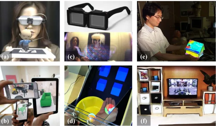
Figure 1.2: Examples of different AR paradigms. (a) VST-AR with closed-view head-worn display (Kato and Billinghurst, 1999). (b) VST-AR with hand-held devices (Ridden, 2013). (c) OST-AR with head-worn optical see-through glasses (Maimone et al., 2014). (d) OST-AR without head-worn glasses (Hilliges et al., 2012). (e) SAR with movable objects (Bandyopadhyay et al., 2001). (f) SAR within static environment (Jones et al., 2013).
how the computer-generated imagery is blended into the user’s real view, or the display type being used, there are three major paradigms of AR:
1. Video See-Through Augmented Reality (VST-AR)uses video cameras to provide the user’s view of the real world and merges the virtual imagery into the live video streams, resulting in augmented video streams. The user views the real-time augmented video stream on the screen, which can be monitors, closed-view head-worn displays (e.g., Figure 1.2 (a)), or hand-held devices (e.g., Figure 1.2 (b)).
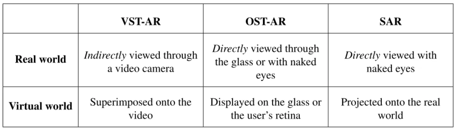
Table 1.1: Summary of the three major AR paradigms.
VST-AR OST-AR SAR
Real world Indirectlyviewed through a video camera
Directlyviewed through the glass or with naked
eyes
Directlyviewed with naked eyes
Virtual world Superimposed onto the video
Displayed on the glass or the user’s retina
Projected onto the real world
see the real world and a virtual environment simultaneously by applying a mirror (i.e., a beam splitter) that is partially transmissive and partially reflective. A different approach is the virtual retinal display (Pryor et al., 1998), which forms images directly on the retina; hence no glasses are required.
3. Spatial Augmented Reality (SAR)uses projectors to seamlessly project virtual imagery directly onto physical objects, offering hands-free and glasses-free immersive experience (e.g., Figure 1.2 (e) and (f)).
Table 1.1 summarizes the differences among these three AR paradigms. 1.1 Registration
Although the ways to combine the real and virtual are different, all types of AR share the same fundamental requirement: registration. The objects in the real and virtual worlds must be properly aligned with respect to each other, or the illusion that the two worlds coexist will be compromised (Azuma, 1997).
An effective persistent illusion requires accurate and stable registration that is bothspatially andtemporallycoherent (Azuma, 1997; Holloway, 1997a; Jacobs et al., 1997):
proper location in the real world with proper real-virtual occlusions, otherwise the user cannot correctly determine spatial relationships.
• Temporal registrationcorresponds to synchronized motion between the real and virtual over time. Virtual objects should be updated and redisplayed at the same time as
corresponding updates and changes in the physical-world scene. End-to-end system latency (also known as motion-to-photon latency) is directly related to temporal
misregistration. It is defined as the time difference between the moment that the object or the viewpoint moves to the moment that the updated virtual image corresponding to the motion appears in the display.
1.1.1 Registration Errors
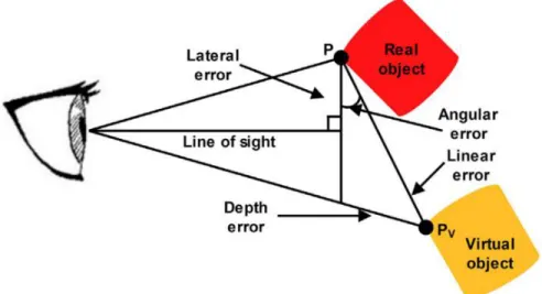
Visible registration errors are present in most AR systems. They are perceived by the user in the final augmented imagery as misalignment between the real and virtual objects. Registration errors can be divided into three categories (Holloway, 1997a): (1) linear registration error, (2) lateral registration error, and (3) depth registration error. An illustration is shown in Figure 1.3.
Figure 1.3: Illustration of registration errors. Source: Daponte et al. (2014).
Static errorsare constant errors arising from geometric processes (calibration, tracking, and modeling), that cause registration errors even when there is no relative motion between the
viewpoint and the object to be augmented. One can say that dynamic error sources cause temporal misregistration, while static error sources cause spatial misregistration. See Holloway (1997a) for a comprehensive analysis of error sources and magnitudes of misregistration.
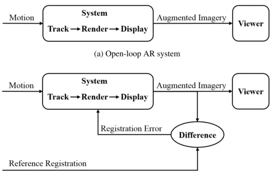
1.1.2 Open-Loop Registration
The conventional method for achieving registration is a four-step process in which
independent mechanisms are used first to do an one-time calibration of system parameters, then to dynamically track the object to be augmented, to render the appropriate virtual content to be overlaid on the real object using the tracking data, and finally to display the result. This is analogous to an open-loop system, shown in Figure 1.4 (a). Such an open-loop system has no mechanism for observing registration errors—it simply generates the virtual content that should be consistent with the geometric process, assuming there are no errors. The only way to improve such system is to make each system component more accurate. However, no matter how carefully we perform the geometric process, we cannot eliminate all errors.
1.1.3 Closed-Loop Registration
Conversely closed-loop AR systems sense their own output (i.e., augmented imagery to be observed by the user), and attempt to minimize any detected errors, as shown in Figure 1.4 (b). Such systems can automatically and continuously adjust system parameters in space and time to maintain the desired augmented appearance.
1.2 Thesis Motivation—“The Last Mile”
(a) Open-loop AR system
(b) Closed-loop AR system
Figure 1.4: Comparison between open-loop and closed-loop AR systems.
1998), manufacturing (Caudell and Mizell, 1992), maintenance (Feiner et al., 1993),
navigation (Feiner et al., 1997), and telepresence (Neumann and Fuchs, 1993). To date, however, AR has been primarily confined to the lab, mainly due to huge challenges involved in achieving “the last mile”1of registration. “The last mile” refers to the final delivery of accurately registered
augmented imagery to the end user, free of perceivable errors. However, registration errors are difficult to adequately control because of the high accuracy requirements and the numerous sources of error (Azuma, 1997).
Among all error sources, system latency is the largest single source of registration error in existing AR systems, outweighing all others combined (Holloway, 1997a). Latency results in temporal misregistration, manifested as virtual imagery lagging behind or “swimming” around the intended position. All AR systems suffer from the unavoidable delay between sampling a sensor and modifying the display. Every action pertaining to the registration, e.g., tracking, rendering, and display, requires some amount of time to occur. Unfortunately, todays hardware (GPUs) and 1The term “the last mile” has its origin in telecommunications and supply chain management. It describes the last
software (drivers and graphics APIs) are not designed for minimal latency but rather for highest possible throughput, which they achieve through a combination of parallelism and pipelining. Even as it increased frame rates, it has been a source of increased latency. Predictive tracking is a good workaround for short delays, but it does not allow us to relax the restraint that the system operates with quick turnaround (Azuma, 1995). Therefore, we must minimize latencies in all system components all the way from motion sensing to photon display, if possible.
Other most serious error sources are in the geometric processes, especially 6DOF pose tracking. An AR system needs to know the geometric relationship between the user’s eyes, the display(s) and the objects in the world. Inaccurate geometric processes result in spatial
misregistration, usually manifested as virtual imagery (1) offset constantly, due to calibration or modeling errors; (2) jittery, due to unstable tracking; or (3) drift-away, due to error accumulation. However, most AR systems are open-loop. The result is that inaccurate geometric processes lead to misregistration that is seen by the users but not the system. Careful measurement of these
geometric relationship will reduce some of these registration errors, but they can never be completely eliminated in any realistic system (MacIntyre and Julier, 2002). Therefore, we must “close the loop” by feeding the output registration back into the system and have the system
automatically minimize any visible errors. 1.3 Thesis Statement and Contributions
This thesis is motivated by “the last mile” of registration in AR—the final imagery observed by the user should be free of perceivable errors. “This last mile” demands AR systems to be low-latency and closed-loop.
Thesis Statement
Closed-loop real-virtual spatial adaptation and low-latency fine-grained render-display processing can be used to achieve optimal visual registration in Augmented Reality systems.
1. I presentreal-virtual model-based registration(RV-MBR) as an effective closed-loop registration method, which continuously adjusts geometric transformation parameters to maintain the desired augmented appearance in projector-based SAR. It does so without the explicit detection and use of features or points in the camera imagery, instead
optimizing the parameters directly using any misregistration manifested in the augmented imagery.
2. I introduceregistration-enforcing model-based tracking(RE-MBT) as a new paradigm for registration in VST-AR, offering a valuable extension to existing AR approaches relying on conventional model-based tracking (MBT). RE-MBT is capable of refining the camera poses towards better registration by selective weighting of important image regions, even in the presence of modeling errors.
3. I show how real-time optical flow can be used in a post-process in VST-AR to minimize residual registration errors in image space, even in the presence of non-rigid errors. I introduce two alternative ways of using (feeding back) the optical flow:forward warping Augmented Reality (FW-AR) andbackward warpingAugmentedVirtuality(BW-AV). The latter uses the camera image to re-texture the rendered real scene model.
4. I propose a low-latency image generation algorithm, reducing latency to the minimum in DLP™ DMD projectors, which are widely used in OST-AR. Grayscale display can be achieved via binary adjustments at the maximum binary rate. The resulting displayed binary image is “neither here nor there,” but always approaches the moving target that is constantly changing desired image, even when that image changes every50µs.
1.4 Thesis Outline
CHAPTER 2: RELATED WORK
This chapter describes previous work in spatio-temporal registration in AR, beginning with a review of misregistration minimization techniques in Section 2.1. This is followed by a discussion of tracking techniques in AR in Section 2.2, as tracking is the most serious source of static
misregistration. Finally, Section 2.3 introduces related work on latency, which is the dynamic error source.
2.1 Registration Errors
If computer-generated imagery is poorly aligned with the real world, it can be confusing, annoying, misleading, or even dangerous for applications such as AR-assisted surgery (Fuchs et al., 1998). The challenges of accurate registration are significant for Video See-Through AR (VST-AR) and projector-based Spatial AR (SAR) systems (e.g, Dedual et al. (2011); Kato and Billinghurst (1999); Bimber and Raskar (2005)) and even more so for Optical See-Through AR (OST-AR) systems (e.g, Menozzi et al. (2014); Sutherland (1968)). Holloway (1997a) conducted a
comprehensive analysis of registration errors and summarized a number of important error sources in OST-AR with head-worn displays, including calibration error, tracking error, system delay, and misalignment of the model. VST-AR and SAR systems suffer from the same major error sources. The principal difference of VST-AR in comparison with SAR and OST-AR is that in VST-AR, the video stream can be deliberately delayed or otherwise modified to match the virtual image in space and time (Bajura and Neumann, 1995).
2.1.1 Direct Misregistration Minimization
Some previous work has attempted to obtain pixel-wise registration adjustments for accurate occlusion between the real and virtual objects. Klein and Drummond (2004) identify boundaries and edges where the real world occludes the virtual imagery and then use the error to adapt polygonal phantom geometry for better real-virtual occlusion. Similarly, DiVerdi and H¨ollerer (2006) use edge searching in a pixel shader to obtain per-pixel occlusion correction, however, they adapt polygon boundaries in screen space rather than adjusting the pose estimate for the entire polygon.
2.1.2 Indirect Misregistration Minimization
Some research tries to work around the registration errors by using pre-registered
augmented images or by attempting to mitigate the consequences of misregistration. The former is exemplified by Indirect AR (Wither et al., 2011), which displays previously acquired panoramas of a scene with carefully registered augmentations, rather than capturing and displaying live images. Similarly, Quarles et al. (2010) allows the user to see a virtual version of the real world around them on their hand-held screen that is roughly registered to the world, but they show only a portion of the scene rather than a complete annotated panoramic image of the world around them. Such indirect methods avoid tracking errors with traditional AR registration and can enable perfect alignment of virtual content, but they only work for VST-AR.
theintentof the augmentation, which are demonstrated to be effective in a user study (Robertson et al., 2009).
2.1.3 Discussion
In contrast to previous work, our proposed closed-loop registration approach minimizes registration errors in both global world space via camera pose refinement and local screen space via pixel-wise corrections, to handle a larger variety of non-rigid registration errors. All of our global world-space misregistration minimization methods (RV-MBR, E-MBR, MBT, and RE-MBT) directly minimize errors in tracking. For local screen-space misregistration minimization methods, FW-AR directly minimizes registration errors in real camera space, while BW-AV can be
considered as an indirect method as it minimizes misregistration by warping the real camera image into the virtual camera space.
2.2 Tracking—Static Error Source
The real-time estimation of eye/camera position and orientation (6DOF pose), also known as “tracking,” has long been considered one of the most crucial aspects of AR (Azuma, 1997). It is so important because for most applications, the perceived quality of an AR display is a direct function of tracking accuracy. Unfortunately, tracking is the most serious source of static errors; even small tracking errors will result in visible registration errors.
In 1968, Ivan Sutherland stated the goal was a resolution of 1/100 of an inch and one part in 10,000 of rotation (Sutherland, 1968). Some of today’s systems claim to achieve position accuracy and resolution of tenths of millimeters, and orientation accuracy and resolution of hundredths of degrees, all with latencies on the order of milliseconds. They do so using a variety of modalities (e.g., magnetic fields, acoustic waves, inertia, and light) in a variety of configurations. In general, we can classify them into three categories: sensor-based, vision-based, and hybrid tracking. 2.2.1 Sensor-Based Tracking
(a) ARToolKit marker (b) ARTag marker (c) Multi-ring marker (d) Random dot marker
Figure 2.1: Sample markers. (a) ARToolKit marker (Kato and Billinghurst, 1999). (b) ARTag marker (Fiala, 2010). (c) Multi-ring marker (Y. Cho and Neumann, 1998). (d) Random dot marker (Uchiyama and Saito, 2011).
vision-based tracking. Sensor-based tracking has been well developed as part of Virtual Reality research. See (Meyer et al., 1992; Bhatnagar, 1993; Rolland et al., 2001; Allen et al., 2001; Welch, 2009) for relatively comprehensive overviews.
2.2.2 Vision-Based Tracking
Arguably the most prevalent approach for tracking in AR is to use computer vision. Vision-based methods offer the advantage that they typically estimate the pose by observing features in the environment near the desired location of the augmentation. The low cost of video cameras and the increasing availability of video capture capabilities in off-the-shelf PCs and mobile devices have inspired substantial research into the use of video cameras as sensors for tracking. 2.2.2.1 Marker-Based Tracking
Marker-based tracking uses fiducial markers (artificial landmarks), which are placed in the scene to facilitate locating point correspondences between images, or between an image and a known model. The most famous marker-based tracking approach is ARToolKit (Kato and
Billinghurst, 1999), which uses a heavy black square frame within which a unique pattern is printed. Rudimentary image processing can be used for marker detection: image thresholding, line finding, and extracting regions bounded by four straight lines. Each marker, having four corners, yields a full 3D pose. Numerous enhancements have been made over ARToolKit, including less
2007), less visual clutter (Wagner et al., 2008a), and robustness to noise (Owen et al., 2002), occlusion (Olson, 2011), and motion blur (Herout et al., 2013). Other researchers explore tracking using non-square markers, such as ring-shaped (Y. Cho and Neumann, 1998), circular 2D
bar-coded (Naimark and Foxlin, 2002), or even randomly scattered dots (Uchiyama and Saito, 2011). Several sample markers are shown in Figure 2.1.
Because of its reliability and efficiency as well as the availability of many open-source libraries, maker-based tracking is widely used for rapid AR application development. While using markers can simplify the 3D tracking task, its main drawback is the requirement of manual
engineering of the environment, which makes it limited to indoor use. 2.2.2.2 Markerless Tracking
Rather than using fiducial markers, markerless tracking relies on natural information present in the camera image, such as points, edges, or image intensities.
Feature-Based Tracking
Feature-based tracking methods track local features such as line segments, edges, or contours across a sequence of images. These techniques are generally robust to lighting change and occlusions, but sensitive to feature detection and they cannot be applied to complex images that do not naturally contain special sets of features to track. Feature-based tracking can be further
classified, according to the type of feature used, into edge-based and point-based.
Edge-based tracking. Edges correspond to discontinuities in image intensities. They are relatively robust to lighting changes and easy to extract from images. Historically, the early approaches to tracking were all edge-based, mostly because these methods are both
predicted and actual edge locations by small, one-dimensional edge searches performed from control points on the CAD model edges, and (3) update 6DOF pose to minimize the difference by linearizing about the current pose estimate, differentiating each edge distance with respect to the six pose parameters and solving for a least-squares solution. Increases in processing power and advances in technique have since given rise to many systems which take the basic ideas of RAPiD to the next level (Armstrong and Zisserman, 1995; Drummond and Cipolla, 2002; Seo et al., 2014). Edge-based tracking methods are generally accurate for estimating small pose changes, but they cannot cope with sudden large camera motions. Therefore, previous AR systems usually combine them with sensor-based tracking to handle a wide variety of motions. Such hybrid approaches are further discussed in Section 2.2.3.
Keypoint-based tracking. Keypoint features, or interest points, e.g., harris corner (Harris and Stephens, 1988), SIFT (Lowe, 2004), or Ferns (Ozuysal et al., 2007), are discriminative image points, usually described by the appearance of patches of pixels surrounding the point location. One of the first AR systems using keypoint-based tracking was done by Park et al. (1999), using natural image points to extend the range and robustness of marker-based tracking. Without the use of any fiducials for initialization, Simon et al. (2000) require the user to manually indicate the planar region in the first frame and then track the planar region continuously. Keypoints are detected in each frame and matched to those detected in the previous frame in order to compute the inter-frame homography, from which the 6DOF pose can be extracted. Wagner et al. (2008b) present the first real-time 6DOF keypoint-based tracking system for mobile phones, which heavily modifies SIFT to be less computationally expensive and Ferns to be less memory intensive.
Intensity-Based Tracking
transformations, such as affine, homography, and rigid-body 6DOF transformation. Baker and Matthews (2004) present a unifying framework to understand and categorize many variants of the Lucas-Kanade (LK) method. One of the notable variants is the Inverse Compositional (IC)
algorithm (Baker and Matthews, 2001), which is as accurate as the LK method but more efficient by making the Hessian matrix constant so that it can be precomputed. Benhimane and Malis (2004, 2007) further improve IC by using efficient second-order minimization (ESM), which achieves a better convergence rate without a loss of accuracy or efficiency.
With intensity-based tracking, the template can be 2D images or 3D textured models. In the case of 2D templates, these methods are also known as template-based tracking (Baker and Matthews, 2001; Benhimane and Malis, 2004, 2007; Lieberknecht et al., 2009). In the case of 3D templates, these methods are also known as 3D model-based tracking (MBT) or
tracking-by-synthesis (Li et al., 1993; Reitmayr and Drummond, 2006; Simon, 2011). Reitmayr and Drummond (2006) use tracking-by-synthesis in AR by rendering a textured model of the real environment for subsequent feature matching with the live video image. While this approach is sparse and intended for pose tracking, it could be used to implement closed-loop tracking in the context of this thesis as well (Section 3.2).
Simultaneous Tracking and Mapping
level, not only tracking a freely-moving color camera but also performing dense reconstruction of the static scene (producing a surface patchwork with millions of vertices) using powerful
commodity GPGPU hardware.
With the introduction of low-cost depth sensors, such as the Microsoft Kinect, RGB-D SLAM methods have become popular in AR (Newcombe et al., 2011b; Meilland et al., 2013; Salas-Moreno et al., 2013, 2014). The most representative work is KinectFusion (Newcombe et al., 2011b), which demonstrates a live dense tracking and reconstruction system with better accuracy and robustness than any previous solution using passive computer vision.
Visual Servoing
Visual servo control refers to the use of computer vision data to control the motion of a robot, relying on techniques from image processing, computer vision, and control
theory (Chaumette and Hutchinson, 2006, 2007). Our closed-loop approach has its roots in conventional control theory. It is related to virtual visual servoing (Comport et al., 2006), whose task is to control the virtual camera using estimated pose to match the real camera for AR registration. Benhimane and Malis (2007) have theoretically proved the existence of the
isomorphism between the task function and the camera pose and the local stability of the control law for homography-based 2D visual servoing.
2.2.3 Hybrid Tracking
tracker, RAPiD (Harris and Stennett, 1990), which is accurate for small motions, with rate
gyroscopes, which are robust to rapid rotations. Recent work by Oskiper et al. (2011) demonstrates a highly-accurate and stable hybrid tracking method for both indoor and outdoor AR over large areas. This approach uses an error-state Extended Kalman Filter (EKF) to fuse Inertial
Measurement Unit (IMU) output, visual odometry based relative pose measurements, and global pose measurements as a result of landmark matching through a pre-built visual landmark database. 2.2.4 Discussion
While we are fortunate to have access to such relatively robust and accurate approaches, as indicated earlier, even the best system/approach cannot ensure accurate real-virtual registration alone, as such systems do not observe or correct the registration in the final augmented image. Errors caused by (for example) manufacturing inaccuracies, signal delays, and dynamic variations in components and parameters conspire against registration. This is compounded by errors in the models for the objects/scenes we are trying to augment. These inevitable errors and perturbations are magnified by distance and other factors, and manifest themselves as misregistered and unstable imagery. This is the motivation for our closed-loop approach, which can be implemented using virtually any tracking system suited to a specific situation, combined with our global-local misregistration minimization.
2.3 Latency—Dynamic Error Source
Latency results in temporal misregistration, manifested as virtual imagery lagging behind or “swimming” around the intended position. It is the single largest source of registration error in
existing AR systems, outweighing all other error sources combined (Holloway, 1997a). End-to-end system latency is the sum of delays from tracking, application, rendering, scanout, display, and synchronization among components (Jerald, 2009):
computer from the computer that executes the application and rendering, tracking delay includes the network delay
• Application delayis time due to computation other than tracking or rendering, e.g., updating the world model, user interaction, and physics simulation. It can vary greatly depending on the complexity of the task and the virtual world.
• Rendering delayis the time from when new data enters the graphics pipeline to the time an image resulting from that data is completely drawn into a buffer (framebuffer). It depends on the complexity of the virtual world, the desired quality of the resulting image, and the performance of the graphics software/hardware.
• Scanout delayis the time from when a pixel is drawn into the framebuffer to the time that pixel is transferred to the display device. Common display interfaces (e.g., VGA, DVI, and HDMI) use raster scan method, which scanning pixels out from the GPU to the display left-to-right in a series of horizontal scanlines from top to bottom (Whitton, 1984). • Display delayis the time from when a pixel arrives at the display device to the time that
pixel’s light reaches users’ eyes. It depends on the technology of the display hardware (e.g., LCD, DLP, and OLED (Wikipedia, 2015a)).
• Synchronization delayis the delay that occurs due to integration of pipelined
components. It can be due to components waiting for a signal to start new computations and/or can be due to asynchrony among components. For example, V-Sync (Vertical Synchronization) is used to synchronize the GPU and display to the vertical blanking interval, where the GPU sends rendered frames to the display on a fixed cadence (60 times per second for a 60 Hz display).
Tracking Delay
Application Delay
Rendering Delay
Scanout Delay
Display Delay
Sy
nchr
oniz
at
ion
Dela
y
The System
The User
Figure 2.2: End-to-end system latency comes from the delay of the individual systems components and from the synchronization of those components [adapted from (Jerald, 2009)].
synchronization delays, and (Ohl et al., 2015) for detailed latency analysis in telepresence systems with distributed acquisition and rendering.
2.3.1 Latency Perception
discrimination is in the5to20ms range (Adelstein et al., 2003; Ellis et al., 2004; Mania et al., 2004), independent of scene complexity and real-world meaning (Mania et al., 2004). Even smaller total latencies are recommended when a VR experience conveying a high sensation of presence is needed: to avoid any perception of scene motion due to latency, values as low as3ms should not be exceeded (Jerald and Whitton, 2009; Jerald, 2009). A NASA study investigating the utility of head-worn displays for flight deck “Synthetic/Enhanced Vision Systems” concludes that
commonplace “head movements of more than100°/s would require less than2.5ms system latency to remain within the allowable [Heads-Up Display] error levels” (Bailey et al., 2004).
Touch-based interaction with displays also represents a form of AR, in that the user should ideally perceive display elements as being affected by touch as if they were tangible objects (e.g. when dragging). Previous work in this related area covers both user perception and task
performance; the conclusions include that “there is a perceptual floor somewhere between2−11ms, below which users do not notice lag” and that “latencies down to2.38ms are required to alleviate user perception when dragging” (Jota et al., 2013; Ng et al., 2012).
2.3.2 Reducing Dynamic Errors
There are four approaches to reducing dynamic registration errors caused by latency: latency minimization, just-in-time image generation, predictive tracking, and video
feedback (Holloway, 1997b; Azuma, 1997). 2.3.2.1 Latency Minimization
This is the most straightforward approach, which aims at directly reducing latencies in system components and making them more responsive. Olano et al. (1995) minimize latency in rendering by reconfiguring the conventional pipeline at the cost of throughput. Their low-latency rendering system reduces image generation time from 50-75 ms to 17 ms. Regan et al. (1999) build a low-latency hardware system for VR consisting of a low-latency mechanical-arm tracker and a low-latency light-field renderer by deliberately over engineering for latency minimization. SCAAT (Single-Constraint-At-A-Time) reduces tracking latency by producing pose estimates as each new low-level sensor measurement is made rather than waiting to form a complete collection of observations (Welch and Bishop, 1997). Stichling et al. (2006) extend synchronous dataflow graphs with linear processing and fine-grained pipelining for vision-based feature tracking to reduce latency and minimize storage for mobile devices.
the overall latency due to dynamic asynchrony, but introduce image tearing. Recently, NVIDIA (2013) introduces G-Sync™ to address the stuttering issue of V-Sync and maximize input responses by making the display accept frames as soon as the GPU has rendered them, while keeping the screen tearing avoidance feature of the V-Sync. AMD introduces a similar but free solution called FreeSync™ (AMD, 2014), which is built upon DisplayPort 1.2a standard (Wikipedia, 2015b), while G-Sync™ requires a costly NVIDIA-made module to be added to the display.
2.3.2.2 Just-In-Time Image Generation
As there is no way of completely eliminating latencies, this approach aims to reduce apparent system delay by feeding tracking data into the rendering pipeline at the latest possible moment. Regan and Pose (1994) present a approach that feeds the head orientation data into the pipeline after rendering a larger view of the scene; the orientation data is then used to select which portion of the extra-large frame buffer to scan out. Kijima and Ojika (2002) propose a similar approach, called reflex HMD, that has hardware latency compensation ability. Jerald et al. (2007) select a portion of each scanline based on the yaw-angle offset (the difference of the rendered orientation and the current orientation just before scanout). Instead of rendering a single 2D image for a specific viewpoint, PixelView (Stewart et al., 2004) constructs a 4D viewpoint-independent buffer, from which a specific view can be extracted according to a predicted viewpoint. Just-in-time pixels (Mine and Bishop, 1993) use the most current estimate of head position in order to compute the value for each pixel (or scanline). In frameless rendering (Bishop et al., 1994), the system draws a randomly distributed subset of the pixels in the image at each frame, allowing each pixel to be computed with the most recent head-motion data. As a follow-up of frameless rendering, Dayal et al. (2005) adapt sampling and reconstruction with very fine granularity to spatio-temporal color change in order to improve temporal coherence in dynamic scenes.
current viewpoint and a predicted one. The WarpEngine (Popescu et al., 2000) realizes a hardware architecture to accelerate 3D warping operations.
Recent work by Smit et al. (2007, 2008, 2009, 2010a,b) introduce a series of methods to achieve image generation and display at the refresh rate of the display using an effective
client-server multi-GPU depth-image warping architecture. The client on one GPU generates new application frames at its own frame rate depending on the scene complexity, while the server on the other GPU performs constant-frame-rate image warping of the most recent application frames based on the latest tracking data. (Smit et al., 2010a) enhances (Smit et al., 2009) with
asynchronous data transfer between the client and the server instead of synchronous data transfer, which significantly reduces the data transfer time. In a similar vein, (Smit et al., 2010a) transmits per-pixel object IDs and the corresponding object transformation matrices instead of directly transmitting the 3D per-pixel motion field as done in (Smit et al., 2010b), leading to reduced data transfer size and increased runtime performance. On the other hand, (Smit et al., 2010b) employs a better client-side camera placement strategy—two client-side cameras are placed adaptively using prediction based on the optic flow of the scene, which dramatically reduces errors caused by occlusion in image warping.
2.3.2.3 Predictive Tracking
These approaches predict future viewpoint and object locations and render the virtual objects with these future locations, rather than currently measured locations. The representative work by Azuma (1995) shows that head-motion prediction with inertial systems gives a 5 to 10-fold increase in accuracy in an AR system. A recent study concludes that predictive tracking can be effectively implemented to reduce apparent latency, resulting in a lower magnitude of simulator sickness while using an optical see-through helmet-mount display (Buker et al., 2012). However, as noted by Azuma (1995), predictive tracking does not allow us to relax the constraint that the system operates with a quick turnaround.
head velocity, which is then used to predict future head orientation. As an alternative to KF based motion prediction, LaViola (2003b) proposes a latency compensation method based on double exponential smoothing, which is shown to produce similar results to the KF while being
“approximately 135 times faster”. Split covariance addition algorithm has also been used for head orientation tracking (Julier and La Viola, 2004), which is shown to be slightly more robust and have slightly more accurate angular velocity estimates than the KF, while the absolute orientation estimate is slightly worse than the EKF. The EKF is found to provide the same performance in typical VR/AR applications as other predictive filtering methods including particle filters and the unscented KF (Van Rhijn et al., 2005). Buker et al. (2012) combine neural network and
extrapolated frame correction (EFC) for predictive tracking in order to reduce apparent latency at a greater percentage at higher head movement frequencies. The authors infer that the neural network algorithms always work with the long prediction in concert with the single frame prediction and adjust to the perspective of the single frame prediction with EFC. To compare different predictors, Azuma and Bishop (1995) introduce a theoretical framework for head motion predictor analysis, while LaViola (2003a) present a testbed for the empirical evaluation of general predictive tracking algorithms, offering both head and hand motion datasets.
2.3.2.4 Video Feedback
In VST-AR systems, the video camera and digitization hardware impose inherent delays on the user’s view of the real world. However, with the digitization of the real world, we have the option of deliberately delaying the real world (i.e., the video stream) to match the virtual world (Bajura and Neumann, 1995).
2.3.3 Discussion
It is important to note that until now, all approaches striving to reduce rendering latency—even unusual ones such as frameless rendering (Bishop et al., 1994; Dayal et al.,
CHAPTER 3: CLOSED-LOOP SPATIAL REGISTRATION
In Augmented Reality (AR), visible misregistration can result from many error sources, including spatial errors in tracking, calibration, and modeling, and temporal errors, i.e., system delays. However, the typical real-virtual registration is “open loop”—inaccurate geometric measuring or latency leads to misregistration in the final imagery that is seen by the users but not the system.
In this chapter, I advocate prioritizing visual registration over geometric accuracy, as real-virtual registration is the overarching goal in AR. This is realized by “closing the loop” in the final user imagery—feed back and minimize registration errors. Section 3.1 introduces closed-loop projector-based Spatial AR (SAR), which employs real-virtual model-based registration (RV-MBR) to continuously adjust geometric transformation parameters to maintain the desired augmented appearance. Section 3.2 introduces closed-loop Video See-Through AR (VST-AR), which employs a novel global-local closed-loop registration framework to minimize misregistration in both global world space via camera pose refinement and local screen space via pixel-wise adjustments.
Section 3.1 and Section 3.2 substantially replicate peer-reviewed papers “A General Approach for Closed-Loop Registration in AR” published at IEEE Virtual Reality (VR) in 2013 (Paper 1, co-authored with Ryan Schubert and Greg Welch) and “Pixel-Wise Closed-Loop Registration in Video-Based Augmented Reality” published at IEEE International Symposium on Mixed and Augmented Reality (ISMAR) in 2014 (Paper 2, co-authored with Dieter Schmalstieg and Greg Welch), respectively. Changes incorporated here include the use of a consistent
3.1 Closed-Loop Projector-Based Spatial AR
The goal of the closed-loop registration concept described in Section 1.1.3 is to minimize the difference between anobservedregistration and areferenceregistration. Different from VST-AR and Optical See-Through AR (OST-AR), SAR has the unique real-virtual relationship that the real and virtual objects coexist in the same physical space. Therefore, we can use a commodity color camera to “observe” the resulting registration, which is the basis for “closing the loop” in the fashion of Figure 1.4 (b).
Specifically, in Section 3.1.1, I introduce RV-MBR which naturally couples tracking, rendering, and display for the purpose of registration. This approach is validated with a real SAR application in Section 3.1.2. Section 3.1.3 shows that RV-MBR can be applied to VST-AR by digitally simulating the “projection”.
3.1.1 Real-Virtual Model-Based Registration
In this section, I explain how to mathematically formulate the closed-loop SAR registration process as illustrated in Figure 3.1 using a single cost function in a projector-camera (ProCam) system. As human observers, we expect to see the correct combined appearance of the real and virtual, i.e., the appearance we observe should match an expected appearance or reference. This suggests a natural formulation of the cost function:
arg min p
X
u
kIˆa(u)−Tˆa(W(u;p))k2 (3.1)
whereIˆais the image we observe, i.e., the combined appearance of the real and virtual, called the
augmented image, whileTˆarepresents the expected combined appearance, called theaugmented
model imageorreference image. The augmented model imageTˆais the 2D appearance of the 3D
augmented modelMa, which is the registered combination of the real object to be tracked, i.e.,real
modelMr, and the virtual object to be overlaid/projected, i.e.,virtual modelMv. For example,
Step 3: Compare with reference image ��(d) and minimize difference
�� � − �� � 2
Real object with real image (reflectance) �� (b) being augmented by projected image Step 1: Project
virtual image
��(a)
Step 2: Capture augmented image
��(c)
(a) Virtual image ��
(d) Reference image �� (b) Real image ��
(c) Augmented image ��
Figure 3.1: Illustration of closed-loop registration in projector-based SAR. This process minimizes the difference between observed registration (c) and reference registration (d) by continuously adjusting the projected imagery (a), closely matching the closed-loop concept described in Sec-tion 1.1.3.
To minimize the 2D image difference, the augmented model imageTˆais synthesized by
transforming the augmented modelMausing the warping functionW(u;p), whereu= (u, v)T is
a 2D column vector containing the pixel coordinates, andp= (p1,· · · , pn)T is a vector of
parameters for arbitrary spatial transformation, e.g., a 2D homography or a 3D pose. For the general case, whereMais not necessarily planar, we use 3D pose parameterization. IfMais planar,
function becomes
W(u;p) = 1 1 +p7u+p8v
(1 +p1)u+p3v +p5
p2u+ (1 +p4)v +p6
(3.2)
And its Jacobian can be computed as (Baker and Matthews, 2004)
∂W ∂p =
1 1 +p7u+p8v
u 0 v 0 1 0 −u[(1+p1)u+p3v+p5]
1+p7u+p8v
−v[(1+p1)u+p3v+p5]
1+p7u+p8v
0 u 0 v 0 1 −u[p2u+(1+p4)v+p6]
1+p7u+p8v
−v[p2u+(1+p4)v+p6]
1+p7u+p8v
(3.3)
For projector-based SAR, the augmented image is a function of light and surface
reflectance. Assuming no environmental light and that the real object is planar and diffuse, then the observed augmented imageIˆacan be approximated as a multiplicative modulation of the projected
lightTˆv, called thevirtual image, the surface reflectanceIˆr, called thereal image, and the cosine
angle between the surface normal and projector light:
ˆ
Ia(u) = ˆTv(W(u;p))·Iˆr(u)·cosθ (3.4)
where the virtual imageTˆv is warped onto the coordinate frame of the real imageIˆr. The coordinate
frames ofIˆaandIˆrare the same. Plugging Equation (3.4) into Equation (3.1), we obtain
X
u
kTˆv(W(u;p))·Iˆr(u)·cosθ−Tˆa(W(u;p))k2 (3.5)
Note that bothTˆv andTˆaare warped using the same warping parameters since they essentially have
the same behavior. That is, wesimultaneouslytrack the real objectIˆr and minimize misregistration
Augmented model image
�� � �; �
Virtual image
�� � �; �
Augmented Image
�� �
R
30 degrees (misregistered)R
V R
V
R
V
15 degrees(misregistered)
0 degree (registered)
Frame N Frame N+1 Frame N+2
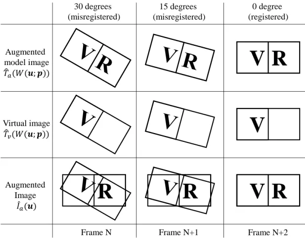
Figure 3.2: An example showing that the augmented model imageTˆaand the virtual imageTˆv are
warped using the same geometric transformation. Assume the real object (with the letter ‘R’) is moved in frame N-1 and static from frame N to N+2. To track the unknown motion of the real object, we iteratively warp both the augmented model image and the virtual image in frame N and N+1 using the incrementally updated parameterpin each frame until the augmented image matches the augmented model image in frame N+2. Note that the virtual image is projected onto the real object in each frame, forming the augmented image.
To simplify the first term in Equation (3.5), we apply a logarithmic transformation to linearize it:
X
u
kTv(W(u;p)) +Ir(u) + log cosθ−Ta(W(u;p))k2 (3.6)
whereTv,Ir, andTaare referred as thelog virtual image,log real imageandlog augmented model
image, respectively. Likewise, the augmented imageIˆaalso has a log formIa:
Equation (3.6) can be effectively solved using conventional gradient descent techniques. In our implementation, we use the Gauss-Newton method to solve the problem, and apply an additive rule to update the motion parameters (Lucas and Kanade, 1981; Baker and Matthews, 2004). The solution of Equation (3.6) is:
∆p=−H−1X
u
(▽Tv −▽Ta)∂W ∂p
T
E(u) (3.8)
p←p+ ∆p (3.9)
where∆pis the incremental motion vector,▽Tv and▽Taare gradients ofTv andTabefore warping,E(u)denotes the error image, i.e.,
E(u) =Ia(u)−Ta(W(u;p)) (3.10)
andH is (Gauss-Newton approximation to the)Hessianmatrix:
H =X
u
(▽Tv−▽Ta)∂W ∂p
T
(▽Tv −▽Ta)∂W ∂p
(3.11)
A summary of the algorithm is shown in Algorithm 1. The ProCam system is assumed to be geometrically calibrated. Note that in the solution Equation (3.8), it is not necessary to compute the angle between the surface normal and the projector light for computing the log augmented image Ia(u)as in Equation (3.7). The reason is that in SAR, the augmented images are “computed”
(combined) optically. To get the augmented image, we project the virtual image onto the scene then capture the resulting appearance using a camera. Hence, in Algorithm 1,Ia(u)is implicitly
“computed” by capturing the scene and then performing a logarithmic transformation. 3.1.2 Empirical Validation
Algorithm 1: Real-virtual model-based registration for planar augmented model Pre-computeGradients▽Tv and▽Taof imagesTv andTa
repeat
WarpTaandTv withW(u;p)to computeTa(W(u;p))andTv(W(u;p))
Compute the error imageE(u) =Ia(u)−Ta(W(u;p))
Warp the gradient▽Tv and▽TawithW(u;p) Evaluate the Jacobian ∂W∂p at(u;p)
Compute the steepest descent image(▽Tv−▽Ta)∂W
∂p Compute the Hessian matrix using Equation (3.11) ComputeP
u h
(▽Tv−▽Ta)∂W
∂p iT
E(u)
Compute∆pusing Equation (3.8) Update the parameters: p←p+ ∆p untilk∆pk ≤ǫ
projected, i.e., Figure 3.1a, while others are printed on the board, i.e., Figure 3.1b. The software for the experiment was implemented on CPU using OpenCV for image processing and the
multithreading API OpenMP for parallelization and speed-ups. The test hardware consisted of a Flea-HICOL (1024x768) camera and an InFoucus 1503D (1280x800) projector, both connected to a computer with an Intel Xeon 2.27 GHz CPU.
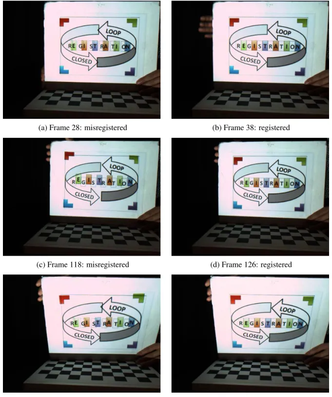
The ProCam system was geometrically calibrated using (Audet and Okutomi, 2009) without color calibration. No extra device was used to synchronize the projector and the camera. We chose to optimize for a 2D homography as both the real and virtual objects in this experiment are planar. The system runs at 10 fps with the current implementation. The algorithm successfully converged for the test sequence, which contains large inter-frame motion and noise. Results are shown in Figure 3.3.
(a) Frame 28: misregistered (b) Frame 38: registered
(c) Frame 118: misregistered (d) Frame 126: registered
(e) Frame 176: misregistered (f) Frame 205: registered
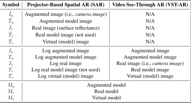
Table 3.1: Summary of mathematical notations for SAR and VST-AR.
Symbol Projector-Based Spatial AR (SAR) Video See-Through AR (VST-AR) ˆ
Ia Augmented image (i.e.,camera image) N/A
ˆ
Ta Augmented model image N/A
ˆ
Ir Real image (surface reflectance) N/A
ˆ
Tr Real model image (not used) N/A
ˆ
Tv Virtual (model) image N/A
Ia Log augmented image Augmented image
Ta Log augmented model image Augmented model image
Ir Log real image Real image (i.e.,camera image)
Tr Log real model image (not used) Real model image
Tv Log virtual (model) image Virtual (model) image
Ma Augmented model
Mr Real model
Mv Virtual model
evaluated the Jacobians numerically. Moreover, even without color calibration or synchronization between the projector and the camera, the method worked well and was robust in handling the test sequences.
3.1.3 Extension to VST-AR
To extend the approach to VST-AR, where the real and virtual do not coexist in the same space, the augmented imageIaneeds to be generated via simulation rather than being combined
optically and captured with a camera, as in SAR. To simplify the notation we useIa,Ta,IrandTv
to represent augmented image, augmented model image, real image and virtual image in VST-AR, instead of using them as log images. The reason is that in VST-AR we can simplify the real-virtual relationship to linear math thus the logarithmic transformation is no longer needed. A simple way to do this, similar to differential rendering (Debevec, 1998), is to consider the relationship as addition, i.e.,
Ia =Tv+Ir (3.12)
That is, we compute the augmented imageIaas the addition of the real image (i.e., the camera
(a) Real model Mr (b) Virtual model Mv (c) Augmented model Ma
(d) Real/camera image Ir (e) Virtual image Tv (f) Augmented image Ia
Figure 3.4: Illustration of augmented image formulation in VST-AR. The augmented modelMa
(c) is the combination/composition (◦) of the real modelMr(a) and the virtual modelMv (b) with
correct relative 3D pose. In this example, the augmented model (c) is composited by placing the virtual 3D model (“bunny”) onto the real textured plane (a) using a graphics engine (e.g., OpenGL). WhenMa and Mr are transformed using the warping functionW(u;p) and projected onto the
virtual camera’s image plane, we obtain the augmented model imageTaand the real model image
Tr, respectively. By subtractingTrfromTa, we obtain the virtual imageTv (e), which captures the
texture of the real modelMr(note the difference in the bunny region between (b) and (e)). Finally,
the augmented imageIa(f) is the addition of the real image (i.e., the camera image)Ir(d) andTv
(e). It is later shown in Section 3.2.1.1 that the texture of the real model captured in the virtual image it is useful for misregistration visualization. Note that this is a synthetic example where the real model (a) with known ideal pose and the camera image (d) with unknown pose (to be estimated) are synthetic. If (a) and (d) were captured/synthesized at the same camera pose, the augmented image (f) and the augmented model view (c) would be the same, i.e., no real-virtual misregistration.
Then to compute the virtual imageTv, we can simply subtract the real model imageTrfrom
the augmented model imageTa, i.e.,
Tv =Ta−Tr (3.13)
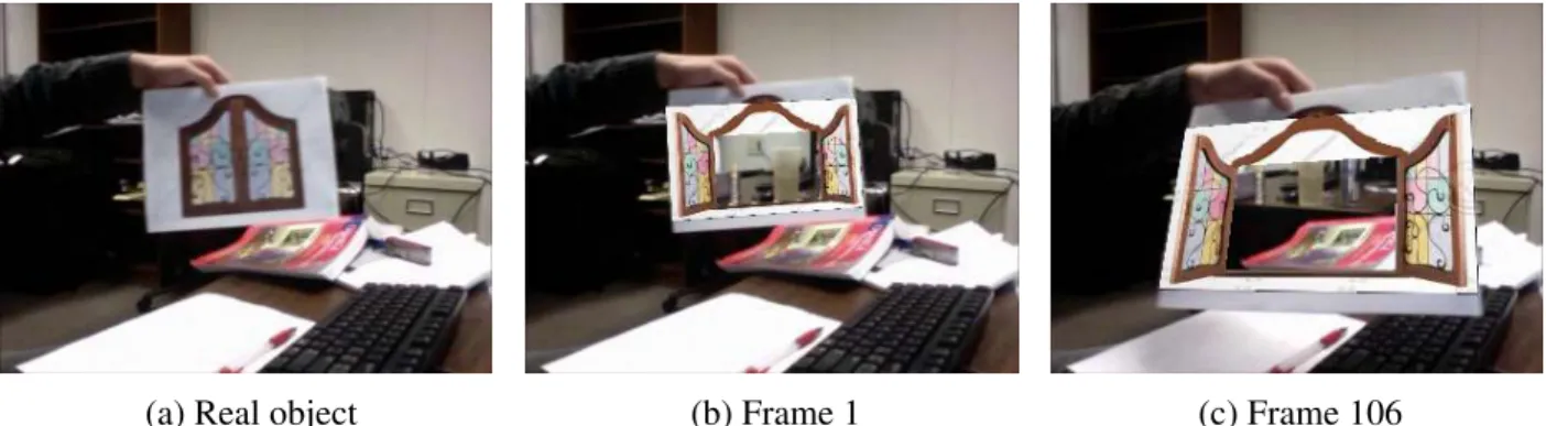
(a) Real object (b) Frame 1 (c) Frame 106
Figure 3.5: Qualitative evaluation of E-MBR in VST-AR and VST-DR. For a single static camera view with a known static background, we tracked the real planar object (a), while “camouflaging” its “closed” window and augmenting it with an “opened” window. Results of two frames are shown in (b) and (c).
The mathematical notations for SAR and VST-AR are summarized in Table 3.1. Note that the real imageIrin VST-AR is the camera image, while in SAR it represents the surface reflectance
of the real object with logarithmic transformation. The reason is that the camera image in SAR captures the appearance of the real object modulated by the projected light (i.e, virtual imageTˆr),
so it represents the augmented imageIˆa.
A qualitative evaluation was performed to show the feasibility of E-MBR in VST-AR as well as Video See-Through Diminished Reality (VST-DR). Diminished Reality (DR) is a special form of AR, which removes an object or collection of objects and replaces it with an appropriate background image (Zokai et al., 2003). It can be considered a real-virtual registration process where the objects are tracked and augmented with virtual content that hides them. DR can also be realized using video see-through, optical see-through and projection-based displays. The result is shown in Figure 3.5.
3.1.3.1 Numerical Comparison with Open-Loop Approach
Two quantitative experiments were conducted, the results of which show that the closed-loop approach outperforms the conventional open-loop approach in terms of registration accuracy. ARToolKit (Kato and Billinghurst, 1999) was chosen as the conventional open-loop approach, as it is widely used in current AR systems. Both of the test sequences used were
perfect knowledge and control of the calibration. The parameters being optimized for were the 3D pose. The error metric being used was the mean absolute error in image intensity
E = 1 N
X
u
|A(u)−B(u)| (3.14)
whereA(u)andB(u)represent the ground-truth image and result image respectively, andN denotes the number of pixels in an image. Both images are grayscale with pixel intensity values in the range [0,255].
Tracker Error
In this experiment, both our approach and ARToolKit were provided with correct
calibration parameters, meaning the registration inaccuracy can be attributed purely to erroneous pose estimates from the tracking system. The test sequence contains a marker, which is initially almost perpendicular to the viewing camera, undergoing a small amount of movement. Visual registration results are shown in Figure 3.6. Figure 3.7 shows numerical results of registration error for each frame. Our results are more stable and accurate while there is a significant amount of jitter in the ARToolKit result. This is because ARToolKit tends to produce unreliable jittery pose estimates with sequences captured from a frontal direction (Mohan et al., 2009).
(a) Our result (b) ARToolKit result (c) Ground truth
Figure 3.7: Numerical comparison in the tracker error experiment. Our results (red curve) are more accurate and stable than ARToolKit (green curve) in terms of mean absolute error in pixel intensity [0, 255].
Calibration Error
In this experiment, I tested the same two approaches with inaccurate calibration data, to simulate another common source of misregistration in AR systems. Specifically, the focal length parameter of the camera calibration data is increasingly degraded. Figure 3.8 shows the registration error for different focal lengths, where focal length f = 500mm is the correct value. For both of the approaches, the registration error increases with the error in focal length. However, our approach still outperformed ARToolKit for all calibration focal lengths.
3.1.4 Summary
(a) Our result (b) ARToolKit result
Figure 3.8: Comparison of registration accuracy with different amounts of error in focal length calibration. Our result (a) is better and contains less registration error than ARToolKit (b). The error metric is mean absolute error in pixel intensity [0,255].
points in the camera imagery, instead optimizing the parameters directly using any misregistration manifested in the augmented imagery. In addition to simplifying the closed-loop registration, this approach can use information implicit in the augmented imagery, such as misregistration
3.2 Closed-Loop Video See-Trough AR
In this section, I present closed-loop VST-AR, which employs a novel global-local closed-loop registration framework to minimize misregistration in both global world space via camera pose refinement and local screen space via pixel-wise adjustments.
Due to the fundamental difference in combining the real and virtual in SAR (light
projection) and VST-AR (digital synthesis), registration error detection in VST-AR can be achieved with a model of the real scene, instead of an augmented model combining both the real scene model and the virtual augmentations. Misregistration can be measured as the image difference between thereal model image—an image rendered from the real scene model using the same projection and viewing parameters as the augmentations, and the current camera image. When any misregistration is detected, it should be minimized in three-dimensional (3D) space. If the real model image matches the camera image, augmentations that are registered to the real scene model will be registered to the camera image.
The above render-compare process suggests that conventional model-based tracking (MBT) or tracking-by-synthesis approaches (Li et al., 1993; Reitmayr and Drummond, 2006; Simon, 2011) are already performing closed-loop registration. As shown in Figure 3.9, our proposed approach differs from such conventional methods in two aspects: (1) we perform both global pose refinement and local pixel-wise adjustments to deal with both rigid and non-rigid registration errors, and (2) we enhance conventional MBT with importance weighting that weights important image regions that have registered virtual objects, which can guide pose refinement towards better registration, even in the presence of modeling errors. For example, when there are errors in the real scene model, conventional methods may compute pose estimates that agree with some parts of the model, but not other parts where augmentations are overlaid, resulting in misregistration as shown in Figure 3.11.
![Figure 2.2: End-to-end system latency comes from the delay of the individual systems components and from the synchronization of those components [adapted from (Jerald, 2009)].](https://thumb-us.123doks.com/thumbv2/123dok_us/8247950.2185556/36.918.178.734.106.501/figure-latency-individual-systems-components-synchronization-components-adapted.webp)