Sharif University of Technology
Scientia IranicaTransactions D: Computer Science & Engineering and Electrical Engineering www.scientiairanica.com
A new algorithm for three-phase power transformer
dierential protection considering eect of
ultra-saturation phenomenon
B. Noshad
, M. Razaz, S.Gh. Seifossadat
Department of Electrical Engineering, Shahid Chamran University of Ahvaz, Ahvaz, Iran. Received 27 February 2013; received in revised form 27 May 2013; accepted 18 June 2013
KEYWORDS Three-phase power transformer dierential protection; Ultra-saturation phenomenon; Magnetic inrush current;
Internal faults; External faults; False trip; Harmonic components; Dierential current.
Abstract.A transient phenomenon that leads to the false trip of the power transformer dierential protection during the energization of a loaded power transformer is the ultra-saturation phenomenon. In this paper, at rst, a new algorithm for three-phase power transformer dierential protection, considering the eect of the ultra-saturation phenomenon, is presented. To model the ultra-saturation phenomenon, the nonlinear characteristic of the transformer core and the eect of saturation of the current transformers are taken into account. It is assumed that the load of the transformer is resistive and inductive. In this algorithm, the ultra-saturation phenomenon, external and internal faults of the power transformer and magnetic inrush current are simulated, and appropriate criteria using the signal harmonic components of the dierential current will be presented for the Discrete Fourier Transform (DFT) algorithm to distinguish between. In this paper, simulation is done by PSCAD and MATLAB programs.
c
2014 Sharif University of Technology. All rights reserved.
1. Introduction
The dierential relay of power transformers is the most important part of power systems [1]. Magnetizing inrush current in the power transformer is a transient phenomenon that can cause the false trip of the transformer dierential protection, as when a power transformer is switched on, it can be much higher than its nominal value and, hence, may cause the false trip of the dierential protections [1-2]. Normally, in order to distinguish between external faults, internal faults and magnetizing inrush current, an algorithm
*. Corresponding author. Tel: +98 611 3330015; Fax: +98 611 3330016
E-mail addresses: [email protected] (B. Noshad); razaz [email protected] (M. Razaz); [email protected] (S.Gh. Seifossadat)
is used in which the dierential protection operates when the amplitude of the basic component of the dierential current is xed higher than 0.25 p.u and the level of the second harmonic to the basic harmonic of the dierential current xes lower than 15% [3-7]. However, it has been shown that under certain conditions, the false trip of dierential protection under magnetizing inrush current has lead to the tripping of healthy transformers [3-5]. When a loaded power transformer is switched on, it may cause a status called the nominated ultra-saturation phenomenon. In this case, the DC ux in the magnetic core of the power transformer at the primary stage of the process in-creases rather than dein-creases [3]. Hence, the amplitude of the basic component of the dierential current gets higher and the level of the second harmonic decreases lower than the level of the relay restrain [3-5]. For analytical study of the ultra-saturation phenomenon,
an initial loaded power transformer energization model was suggested and the false trip of the dierential protection has been described using this model, [3-5]. In [3], many simplications during the simulations are carried out, which take the magnetizing reactance of the time-variant characteristic as an equivalent inductance, neglecting the core model of the power transformer, without considering the transferring eect of the current transformer to the primary inrush, and only considering the resistive load, which does not coincide with real situations. Weng et al. revised their previous model in 2007. According to them, the previous model cannot be used to study the ultra-saturation phenomenon. So, a new model for studying the ultra-saturation phenomenon during loaded power transformer energization is proposed with the current transformer model, including the eect of the magnetic hysteresis and the nonlinear magnetizing reactance, not only the resistive load [4]. But in [4], the core losses of the power transformer are neglected and a dicult model for the current transformer in the primary side is considered whose main diculty in current transformer modeling is the hysteresis loop sim-ulation. Wiszniewski et al. illustrated the conditions which must be discovered to make ultra-saturation and excessive ultra-saturation possible in 2008 [5]. The ATP-EMTP program is used for simulation. For determining the conditions that discovered the ultra-saturation and excessive ultra-ultra-saturation phenomenon in [5], the core model of the power transformer and the magnetizing reactance are ignored, which does not correspond with the real status. In all previous studies of ultra-saturation phenomenon, the model of a loaded power transformer was considered as single-phase and an appropriate protection algorithm had not been described for preventing the false trip of dierential protection due to the ultra-saturation phe-nomenon [3-5]. Several studies have been done to distinguish internal faults from external faults and magnetic inrush current using various algorithms, such as wavelet transform [8,9], the fuzzy technique [10,11], the neural network [12,13], combined wavelet trans-form and neural network [14], harmonic restraint [15] and park transform [16]. Also, some work has used special algorithms, such as short-time correction trans-form [17], the support vector machine-based protection scheme [18], self adaptive transformer dierential pro-tection [19], time-domain analysis of the dierential power signal [20], an inner bridge connection [21], standard 87T dierential protection for a power trans-former and a special power transtrans-former [22,23] and intelligent hybrid systems [24] to distinguish between the transient phenomena. But, in all these studies, the ultra-saturation phenomenon was not taken into account.
In this paper, at rst, a new model for
investigat-ing the ultra-saturation phenomenon durinvestigat-ing the ener-gization of a loaded three-phase power transformer is presented. To model the ultra-saturation phenomenon, the nonlinear characteristic of the transformer core and the saturation eect of current transformers are taken into account. It is assumed that the load of the transformer is a resistive and inductive load. Also, a new model is presented for the current transformer which is very simple and eective. In addition to a new model for the power transformer and the current transformer, in this paper, a new algorithm for three-phase power transformer dierential protection, con-sidering the eect of the ultra-saturation phenomenon, is presented. In this algorithm, the ultra-saturation phenomenon, power transformer external faults (in-cluding three-phase fault, three-phase-to-ground fault, to-ground fault, to-phase fault, and phase-to-phase-to-ground fault), power transformer internal faults (including turn-to-ground fault, turn-to-turn fault, and phase-to-phase fault), and magnetic inrush current are simulated, and appropriate criteria using signal harmonic components of the dierential current to distinguish between these phenomenon using the DFT algorithm will be presented. The dierential protection of the power transformer must be fast and accurate, so the description and control of the ultra-saturation phenomenon are necessary for preventing the false trip of the dierential protection. In this paper, simulation is done by PSCAD and MATLAB programs.
2. Ultra-saturation modeling
2.1. Modeling of loaded three-phase transformer energization
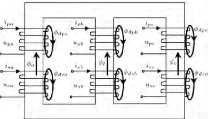
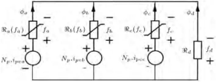
The modeling of power transformers is always done using both magnetic and electrical circuits. The basic structure of a phase, two-winding, three-legged power transformer is shown in Figure 1(a); Figure 1(b) shows the magnetic equivalent circuit of the transformer shown in Figure 1(a). According to
Figure 1a. The basic structure of a three-phase, two-winding, three-legged power transformer.
Figure 1b. The magnetic equivalent circuit of three-phase transformer.
Figure 1(b):
Npipea+ fa <dd= 0; (1)
Npipeb+ fb <dd= 0; (2)
Npipec+ fc <dd= 0; (3)
a+ b+ c+ d = 0: (4)
By considering the saturation curve, reluctances a, b, and c in Figure 1(b) are nonlinear and dened as follows [25]:
<a(fa) 1= k1a
1 +jfaj
f0a
pa1
pa + k2a; (5)
<b(fb) 1= k1b
1 +jfbj
f0b
pb1
pb + k2b; (6)
<c(fc) 1= k1c
1 +jfcj
f0c
pcpc1 + k2c: (7)
According to Figure 1(b):
fa= <a(fa):a; (8)
fb= <b(fb):b; (9)
fc= <c(fc):c: (10)
Due to Eqs. (5)-(10):
a=
0 B B
@ k1a 1 +jfaj
f0a
pa1 pa + k2a
1 C C
A :fa; (11)
b=
0 B B
@ k1b 1 +jfbj
f0b
pbpb1 + k2b
1 C C
A :fb; (12)
c=
0 B B
@ k1c 1 +jfcj
f0c
pcpc1 + k2c
1 C C
A :fc: (13)
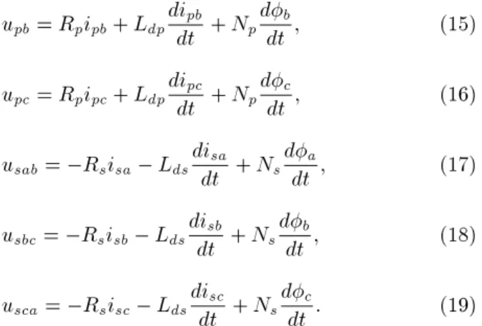
According to the fact that most three-phase power transformers are connected as a YN/d connection, the electric equivalent circuit can be shown in Figure 2. According to Figure 2, the following equations are presented:
upa= Rpipa+ Ldpdidtpa+ Npddta; (14)
upb = Rpipb+ Ldpdidtpb + Npddtb; (15)
upc = Rpipc+ Ldpdidtpc + Npddtc; (16)
usab = Rsisa Ldsdidtsa + Nsddta; (17)
usbc = Rsisb Ldsdidtsb + Nsddtb; (18)
usca = Rsisc Ldsdidtsc+ Nsddtc: (19)
For simulating the ultra-saturation phenomenon, the three-phase power transformer is loaded and it is as-sumed that the balanced three-phase load of the power transformer is resistive and inductive. By connecting the complex load (Rb Lb) in Wye form to the
equivalent circuit of the three-phase power transformer in Figure 2, and based on Kirchho voltage and current laws in the secondary side, the following equations can be written:
usab = Rbia+ Lbdidta Rbib Lbdidtb; (20)
usbc = Rbib+ Lbdidtb Rbic Lbdidtc; (21)
usca = Rbic+ Lbdidtc Rbia Lbdidta; (22)
ia= isa isc; (23)
ib= isb isa; (24)
ic= isc isb: (25)
Due to Eqs. (17)-(25):
Rsisa Ldsdidtsa + Nsddta = Rb(isa isc)
+ Lbd(isadt isc) Rb(isb isa)
Lbd(isbdt isa); (26)
Rsisb Ldsdidtsb + Nsddtb = Rb(isb isa)
+ Lbd(isbdt isa) Rb(isc isb)
Lbd(iscdt isb); (27)
Rsisc Ldsdidtsc + Nsddtc = Rb(isc isb)
+ Lbd(iscdt isb) Rb(isa isc)
Lbd(isadt isc): (28)
Also, according to Figure 2: ipa= ipea+ (Ns=Np)isa;
ipb= ipeb+ (Ns=Np)isb;
ipc = ipec+ (Ns=Np)isc: (29)
In Eqs. (1)-(29) and Figures 1-3, upa, upb, upc, usab,
usbc, usca, ipa, ipb, ipc, ia, iband icare the voltages and
currents of the primary and secondary windings. Rp,
Rs, Ldp and Lds are the resistance and inductance of
the primary and secondary windings. a, b, cand d
are the ux of the core magnetic through the winding legs and air branch. Np and Ns are the primary and
secondary windings turn. epa, epb, epc, esa, esb and
Figure 3a. The current transformer model.
Figure 3b. The current transformer model referred to as secondary side.
Figure 3c. The magnetizing characteristic of transformer core.
esc are the inducted primary and secondary voltages
of winding legs. fa, fb, fc and fd are the magnetic
potential through the three-legged and air branch. pa,
pb, pc, k1a, k1b, k1c, k2a, k2b, k2c, f0a, f0b and f0c are
related to the transformer saturation curve, and Rb
and Lb are resistive and inductive load of the power
transformer.
2.2. Current transformer modeling
In this paper, a new simple and eective model is presented for the current transformer. The current transformer equivalent circuit and the current trans-former equivalent circuit referred to in the secondary side are shown in Figures 3(a) and 3(b). In these circuits, R1 and L1 are the resistive and inductive
components of the equivalent impedance, comprised of the system impedance and leakage impedance of the transformer primary winding; R2 and L2 are the
resistive and inductive winding of the secondary side of the current transformer; and Rb and Lb are the
resistive and inductive burden of the current trans-former. To explain the current transformer model in this paper, an appropriate model is developed to predict the transient behavior of a current transformer with a burden consisting of inductance and resistance, taking saturation into account. To model the current transformer, Figures 3(a) and 3(b) are considered. Since the core loss does not aect the behavior of the current transformer saturation, it is neglected [26]. Although the hysteresis eect is not taken into account in this proposed model, but is considered by the IEEE Power System Relaying Committee (IPSR), both results are in good agreement. The main advantages of this proposed model are as follows:
1. Information concerning the B-H curve for the mag-netic branch is not required.
2. The hysteresis eect is not taken into account and the results of the proposed model can be compared with the IEEE model considering the hysteresis eect.
3. It involves proper computing speed and accuracy. If fault occurs in the primary winding of the current transformer and the fault current passes through the primary winding, the core ux increases due to the asymmetrical component. So, the current transformer core approaches the saturation region and this leads to a secondary current distortion. Therefore, an eective current transformer model for protection systems is required, and, in this paper, a very simple and eective model for a current transformer is presented. The ac-curate curve of the magnetizing curve should be shown as multi-valued if taking hysteresis into account. For the convenience of solving the dierential equations, the magnetization curve can be simplied, as shown in
Figure 3(c). We suppose that the saturation point is (i0; s). The inductance inside and outside the
satu-ration regions are Ls and L, respectively. It should
be emphasized that the inductance of the magnetizing branch of the transformer is still nonlinear, even if the above-mentioned simplication is used. In most papers, in the linear region of the approximate curve, the magnetization current is considered zero, but, in this model, the magnetization curve is considered accurately. Thus, the magnetization curve illustrated in Figure 3(c) is used for the current transformer core. This single-valued magnetization curve is used for the current transformer. Since the hysteresis characteristic does not considerably aect the current transformer transient behavior [27], the single-valued curve is an appropriate curve for transient analysis of the current transformer and can be used instead of a multi-valued curve. According to Figure 3(c):
i=
8 > > > > > > < > > > > > > : s
Ls + i0 > s + s
Ls i0 < s
i0 s j j s
(30)
In this equation, represents the ux linkages, s
represents the ux linkages at the saturation knee point of the magnetization curve, i0 represents the
magnetization current at the saturation knee point of the magnetization curve, and Ls represents the
slope of the saturation zone. To model the current transformer, the equivalent circuit shown in Figure 3(b) is considered. In this circuit, we dened:
R = R2+ Rb; L = L2+ Lb: (31)
According to the equivalent circuit shown in Fig-ure 3(b):
ips= i+ is; (32)
es= Ris+ Ldidts; (33)
ips=NNp
sip: (34)
In these equations, ips represents the primary current
that refers to the secondary side, i is the magnetizing
current, is is the secondary current, Np is the number
of primary turns, Nsis the number of secondary turns,
and esrepresents the induced voltage in the secondary
winding. According to Eq. (32):
is= ips i: (35)
the current transformer has three regions. For region 1, > s:
i= ( L s)
s + i0: (36)
According to Eqs. (35) and (36): is= ips L1
s( s) i0: (37)
Dierentiate from Eq. (37): dis dt = dips dt 1 Ls d
dt : (38)
Due to d
dt = es, from Eqs. (33), (37) and (38):
d
dt = RLs
Ls+ L
ips ( L s)
s i0
+LLLs
s+ L
dips
dt
: (39)
For region 2, < S:
i= L1
s( + s) i0: (40)
According to Eqs. (35) and (40): is= ips L1
s( + s) + i0: (41)
Dierentiate from Eq. (41): dis dt = dips dt 1 Ls d
dt : (42)
Due to d
dt = es, from Eqs. (33), (41) and (42):
d
dt = RLs
Ls+ L
ips ( L+ s) s + i0
+LLLs
s+ L
dips
dt
: (43)
For region 3, j j s:
i= i0
s: (44)
According to Eqs. (35) and (44): is= ips i0
s: (45)
Dierentiate from Eq. (45): dis
dt = dips
dt i0
s
d
dt : (46)
Due to d
dt = es, from Eqs. (33), (45) and (46):
d
dt = R s s+Li0
ips i0
s
+ L s
s+Li0
dips dt : (47)
3. Proposed algorithm for the dierential protection
The dierential protection should be able to distinguish between internal and external faults, the magnetizing inrush current and the ultra-saturation phenomenon, and it should only operate under internal faults. Several studies have been done to distinguish inter-nal faults from exterinter-nal faults and magnetic inrush current by various algorithms, but, in all studies, the ultra-saturation phenomenon was not taken into account. In this paper, at rst, a new model for investigating the ultra-saturation phenomenon during the energization of a loaded three-phase power trans-former is presented. For modeling the ultra-saturation phenomenon, modeling of the power transformer and the current transformer on the primary and secondary sides of the power transformer is required. So, by using Eqs. (1)-(29), the power transformer is modeled, as described in Section 2.1. By using Eqs. (1)-(29), the magnetic linkage of the transformer core and the primary and secondary currents of the three-phase power transformer are calculated. The primary currents of the power transformer are the primary currents of the current transformers on the primary side of the power transformer, and the secondary currents of the power transformer are the primary currents of the current transformers on the secondary side of the power transformer. The dierential currents are calculated by subtraction between secondary currents of the current transformers on the primary and secondary sides of the power transformer, and they will reach the dierential relay. Therefore, to calculate the dierential currents, modeling of the current transformer is required using Eqs. (30)-(47) in Section 2.2. On the other hand, using Eqs. (1)-(47) for the power transformer and the cur-rent transformers, the ultra-saturation phenomenon is modeled and the unusually false trip of the dierential protection due to the ultra-saturation phenomenon is presented using the DFT algorithm of the dierential currents. In this algorithm, the PSACAD program is also used for simulating the inrush current, and internal and external faults. Normally, in order to distinguish between external faults, internal faults and magnetizing inrush current, an algorithm is used in which the dierential protection operates when the amplitude of the basic component of the dierential current xes higher than 0.25 p.u, and the level of the second harmonic to the basic harmonic of the dierential current xes lower than 15%. However, it has been shown that under certain conditions, the false trip of the dierential protection under the ultra-saturation phenomenon has lead to the tripping of healthy transformers. In this algorithm, to distinguish internal from external faults, the magnetizing inrush current and the ultra-saturation phenomenon, rst
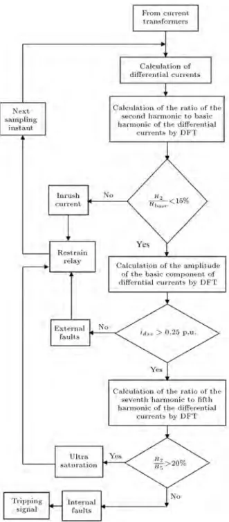
the dierential currents of phases are obtained from subtraction of the secondary currents of the current transformers from the primary and secondary sides of the power transformers. Then, to distinguish between transient phenomena, appropriate criteria using signal harmonic components of dierential currents will be presented by the DFT algorithm. Finally, the following steps are performed to distinguish transient phenom-ena:
a) At rst, the ratio of the second harmonic to the basic harmonic ( H2
Hbase) of the dierential currents is
calculated by the use of the DFT algorithm. If the ratio xes higher than 15%, the inrush current will occur. Otherwise, the other transient phenomena may occur.
b) In the next step, the steady state amplitudes of the basic component of the dierential currents (idss)
are calculated using the DFT algorithm. If the steady state amplitudes x lower than 0.25 p.u., external faults will occur. Otherwise, the ultra-saturation phenomenon or internal faults may oc-cur.
c) In the last step, to distinguish between the ultra-saturation phenomenon and the internal faults, the ratio of the seventh harmonic to the fth harmonic (H7
H5) of the dierential currents is calculated using
the DFT algorithm. If this ratio stabilizes below 20%, an internal fault occurs and the dierential protection must operate.
On the other hand, if the amplitudes of the dierential currents stabilize higher than 0.25 p.u., the ratio change of the second harmonic to the basic harmonic stabilizes lower than 15% and the seventh harmonic to the fth harmonic stabilizes lower than 20%, an internal fault occurs and a dierential relay should be operated. Otherwise, the other transient phenomena may occur and the dierential relay will not operate. To prove the results in the next section, the proposed algorithm is investigated for various cases of transient phenomena. The owchart of the proposed algorithm is shown in Figure 4.
4. Simulation results
4.1. Simulation of the ultra-saturation phenomenon
It is supposed that the three-phase power transformer is load connected and is switched on from the high-voltage side at t = 0. The source and three-phase power transformer parameters are:
upa= Umsin(!t + );
upb = Umsin(!t + 120);
Figure 4. The owchart of the proposed algorithm.
upc = Umsin(!t + 240);
Um= 400 kV; ! = 100 rad; = 80;
k = 400=230 kV; Rp= 0:9 ;
Ldp= 0:1019 H; Rs= 0:5 ;
Lds= 0:0337 H; Np= 610;
S = 500 MVA; <d= 2500 A.t/Wb;
f0a = 10:05 A.t; pa = 5;
k1a= 28 Wb/A.t; k2a = 0:995 Wb/A.t;
f0b= 10:03 A.t; pb= 5;
k1b= 45 Wb/A.t; k2a= 0:9152 Wb/A.t;
f0c= 10:05 A.t; pc= 5;
k1c= 28 Wb/A.t; k2c= 0:9134 Wb/A.t:
a(0) = 1:5878 e 3wb; b(0) = 4:7619 e 3 wb;
a(0) = 6:3518 e 3wb:
Parameters for the current transformer on the high-voltage side of the power transformer are:
k = 600=5; Bs= 1:8 T; Ls= 0:7 mH;
A = 3:472 e 3m2;
s= 0:75 (wb*turns);
i0 = 0:05 mA; R = 0:05 :
Parameters for the current transformer on the low-voltage side of the power transformer are:
k = 1000=5; Bs= 1:9 T; Ls= 0:7 mH;
A = 3:53 e 3m2;
s= 1:34 (wb*turns);
i0= 0:03 mA; R = 0:15 :
For modeling of the ultra-saturation phenomenon, ipa,
ipb, ipc, ia, ib, ic, a, b and c can be solved from
Eqs. (1)-(4), (11), (16) and (23)-(29). ipa, ipb, ipc,
ia, ib and ic are the primary and secondary currents
of the three-phase power transformer. ipa, ipb and
ipc are the primary currents of current transformers
on the primary side of the power transformer, and ia, ib and ic are the primary currents of current
transformers on the secondary side of the power trans-former. Now, the secondary currents of the current transformers on the primary and secondary sides of the power transformer should be calculated. is
related to the current transformers on the primary and secondary sides of the power transformer, and can be solved from Eqs. (39), (43) and (47) using the fourth-order Runge-Kutta method with a 10s time step. The magnetic current, i, according to
Eq. (30), and the secondary current of the current transformers, according to given Eqs. (37), (41) and (45), have been calculated using the computed . In
these relations, ipsis the primary current of the power
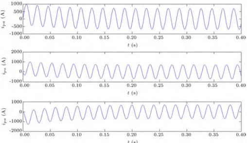
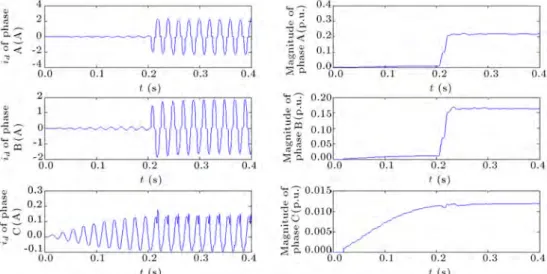
transformer. The wave forms of the magnetic linkage of the transformer core, and the primary and secondary currents of the three-phase power transformer due to ultra-saturation are shown in Figures 5(a), 5(b) and 5(c), respectively. The dierential currents (id) due to
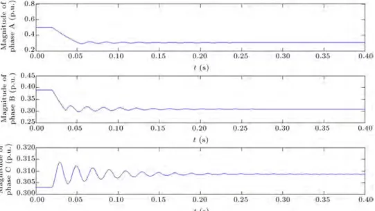
the ultra-saturation phenomenon that are calculated by subtraction between the secondary currents of the current transformers on the primary and secondary sides of the power transformer is shown in Figure 5(d). Figure 6(a) displays the changes of the amplitudes of the basic component of the dierential currents in Figure 5(d), obtained with the DFT algorithm. In this gure, the amplitudes of the basic component of
Figure 5b. Wave shapes of the primary currents of transformer due to the ultra-saturation phenomenon.
Figure 5c. Wave shapes of the secondary currents of transformer due to the ultra-saturation phenomenon.
Figure 6a. The normalized amplitudes of the basic component of the dierential currents with DFT algorithm due to the ultra-saturation phenomenon.
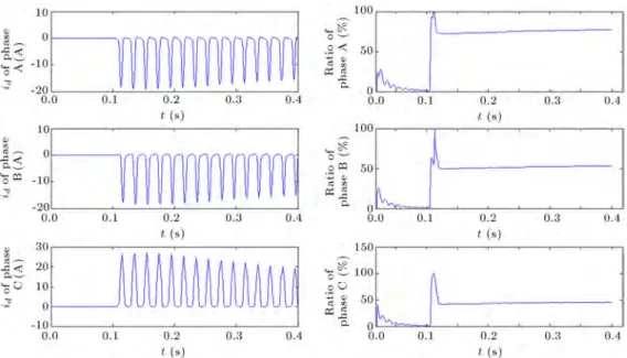
Figure 6b. The ratio of the second harmonic to basic harmonic of the dierential currents with DFT algorithm due to the ultra-saturation phenomenon.
the dierential current are normalized according to the secondary current of the current transformers (5A). Figure 6(b) displays the ratio change of the second harmonic to the basic harmonic of the dierential currents, which is obtained with the DFT algorithm. As illustrated in Figure 6(a), the basic component of the dierential currents is above 0.25 p.u. From the beginning of energization and after, approximately, 6 cycles, it is stabilized above 0.25 p.u. Also, according to Figure 6(b), as the energization time exceeds 0.1344 s, 0.1463 s and 0.1537 s for A, B, and C phases, respec-tively, the ratio of the second harmonic to the basic harmonic stabilizes lower than 15%. So, according to Figures 6(a) and 6(b), if the dierential protection uses 0.25 p.u. as the operating threshold for the amplitudes
of the basic component of dierential currents, and 15% as the second harmonic restraint ratio, the false trip occurs at 0.1344s.
4.2. Simulation of the inrush current
If the amplitude and polarity of the residual ux are not in agreement with the amplitude and polarity of the instantaneous value of the steady state ux, inrush current happens. So, when a transformer is switched on, inrush currents are caused by saturation eects in the magnetic core. One of the important characteristics of inrush current in the dierential relay is the second harmonic. The level of the second harmonic in inrush current is high, and the value of the second harmonic is a function of the degree of saturation. Hence, to
Figure 7a. The dierential currents and the ratio of the second harmonic to basic harmonic of the dierential currents due to inrush current by the change of the residual ux.
Figure 7b. The dierential currents and the ratio of the second harmonic to basic harmonic of the dierential currents due to inrush current by the change of the switching time.
determine the degree of saturation caused by transient inrush currents from steady state currents, the content of the second harmonic is used. So, in the proposed algorithm, the second harmonic is used for distinguish-ing inrush current from steady state currents and other transient phenomena. For simulation of the inrush cur-rent, the unloading transformer is switched on at 0.1 s. Showing the accuracy of the proposed algorithm under all conditions, various test signals by changing some parameters are simulated. Some important parameters such as residual ux, switching time and inception angle have a direct impact on magnetic inrush currents. So, to prove the results of the proposed algorithm, some
dierent signals due to inrush current are generated by the change of residual ux, switching time and inception angle. At various transient inrush currents in the power transformer, 60 test signals for dierent condition of the inrush current are simulated. Due to limitation of paper length, some cases of inrush current are shown in Figures 7(a), 7(b) and 7(c). In these gures, the dierential currents and the ratio of the second harmonic to the basic harmonic of the dierential currents due to inrush current, by changes in residual ux, switching time and inception angle, are shown. According to these gures, the ratio change of the second harmonic to the basic harmonic of the
Figure 7c. The dierential currents and the ratio of the second harmonic to basic harmonic of the dierential currents due to inrush current by the change of the inception angle.
Figure 8a. The dierential currents and the normalized amplitudes of the basic component of the dierential currents due to the three-phase external fault by the change of the residual ux.
dierential currents due to the inrush current always stabilizes higher than 15%. Therefore, the dierential protection under the inrush current condition will not operate. The obtained results for inrush current show the accuracy of the proposed algorithm.
4.3. Simulation of the external faults
For simulation of the external faults, PSCAD and MATLAB programs are used. Fault is occurred on the outside of the protective zone of the dierential relay on the load side. The simulated fault types are the three-phase fault, the three-phase-to-ground fault, the phase-to-ground fault, the phase-to-phase
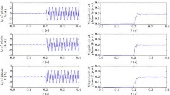
fault and the phase-to-phase-to-ground fault. In the external faults, dierent signals are generated by the change of the residual ux, load level, fault resistance, inception angle and fault occurrence time. At various transient external faults in the power transformer, 500 test signals for dierent conditions of external faults are simulated. Due to the limitation of paper length, some cases of external faults by changes in residual ux, load level, fault resistance, inception angle and fault occurrence time are shown in Figures 8(a) to 8(e). For simulation of the external faults, the time of fault occurrence is considered 0.2 s. In these gures, the dierential currents and the steady state
ampli-Figure 8b. The dierential currents and the normalized amplitudes of the basic component of the dierential currents due to the three-phase-to-ground external fault by the change of the load level.
Figure 8c. The dierential currents and the normalized amplitudes of the basic component of the dierential currents due to the phase-to-phase external fault by the change of the occurrence time.
Figure 8d. The dierential currents and the normalized amplitudes of the basic component of the dierential currents due to the phase-to-phase-to-ground external fault by the change of the inception angle.
Figure 8e. The dierential currents and the normalized amplitudes of the basic component of the dierential currents due to the phase-to-ground external fault by the change of the fault resistance.
Figure 9a. The dierential currents, the normalized amplitudes of the basic component of the dierential currents and the ratio of the second harmonic to basic harmonic of the dierential currents due to the turn-to-ground internal fault by the change of the residual ux.
tudes of the dierential currents due to the external faults by changes in residual ux, load level, fault resistance, inception angle and fault occurrence time are shown. According to these gures, the amplitudes of the dierential currents due to the external faults stabilize lower than 0.25 p.u. Therefore, the dierential protection under the external faults condition will not operate.
4.4. Simulation of the internal faults
For simulating the internal faults of the power trans-former which involve turn-to-ground, turn-to-turn and phase-to-phase, PSCAD and MATLAB programs are also used. In the turn-to-ground fault, the fault is
occurred on the secondary winding of phase A at the 25% position of winding, and in the turn-to-turn fault, the fault is occurred on the secondary winding of phase A in which 10 percent of the turns are short circuited. In the phase-to-phase fault, the fault is occurred on the secondary windings of phases A and B at the 25% position of windings. In the internal faults, dierent signals are generated by the changes in residual ux, load level, fault resistance, inception angle and fault occurrence time. At various transient internal faults in the power transformer, 300 test signals for dierent conditions of internal faults are simulated. Due to the limitation of paper length, some cases of internal faults are shown in Figures 9(a), 9(b) and 9(c). For
simu-Figure 9b. The dierential currents, the normalized amplitudes of the basic component of the dierential currents and the ratio of the second harmonic to basic harmonic of the dierential currents due to the turn-to-turn internal fault by the change of the load level.
Figure 9c. The dierential currents, the normalized amplitudes of the basic component of the dierential currents and the ratio of the second harmonic to basic harmonic of the dierential currents due to the phase-to-phase internal fault by the change of the inception angle.
lation of internal faults, the time of fault occurrence is considered 0.2 s. In these gures, the dierential currents, the steady state amplitudes of the dierential currents and the ratio of the second harmonic to basic harmonic of the dierential currents, due to internal faults, by changes in residual ux, load level and inception angle, are shown. According to these gures, the amplitudes of the basic component and the ratio change of the second harmonic to the basic harmonic of the dierential currents, due to internal faults, exceed threshold values and the dierential protection will operate.
4.5. Distinguish between the ultra-saturation phenomenon and the internal faults According to simulations, if the dierential protec-tion uses 0.25 p.u. as the operating threshold for amplitudes of dierential currents, and 15% as the second harmonic restraint ratio, the dierential re-lay, due to the ultra-saturation phenomenon and the internal faults, will operate. The dierential relay is used for protecting transformers against internal faults, but it should not operate under the ultra-saturation phenomenon. Therefore, to distinguish the internal faults from the ultra-saturation phenomenon,
Figure 10a. The ratio of the seventh harmonic to the fth harmonic of the dierential currents due to the turn-to-ground internal fault by the change of the residual ux.
Figure 10b. The ratio of the seventh harmonic to the fth harmonic of the dierential currents due to the turn-to-turn internal fault by the change of the load level.
the ratio of the seventh harmonic to the fth harmonic is another criterion that is necessary for preventing the false trip of the dierential protection due to the ultra-saturation phenomenon. At various transient phenomena in the power transformer, 380 test sig-nals involving internal faults and the ultra-saturation phenomenon are simulated. In the ultra-saturation phenomenon, dierent signals are generated by the changes in residual ux, load level, inception angle and dierent state of current transformer saturation. In the internal faults, as mentioned, dierent signals are generated by the changes in residual ux, load level, fault resistance, inception angle and fault occurrence time. Figures 10(a), 10(b) and 10(c) show the ratio change of the seventh harmonic to the fth harmonic of the dierential currents, due to internal faults, and
Figures 11(a) to 11(d) show the dierential currents and the ratio change of the seventh harmonic to the fth harmonic of the dierential currents, due to the ultra-saturation phenomenon, which are obtained with the DFT algorithm. According to these gures, if the ratio change of the seventh harmonic to the fth harmonic of the dierential currents stabilizes lower than 20%, an internal fault occurs and the dierential protection should operate. On the other hand, if the amplitudes of the dierential currents stabilize higher than 0.25 p.u., the ratio change of the second harmonic to the basic harmonic stabilizes lower than 15% and the seventh harmonic to the fth harmonic stabilizes higher than 20%, the ultra-saturation phenomenon occurs and the dierential relay, due to the ultra-saturation phenomenon, will not operate. As mentioned, this
Figure 10c. The ratio of the seventh harmonic to the fth harmonic of the dierential currents due to the phase-to-phase internal fault by the change of the inception angle.
Figure 11a. The dierential currents and the ratio of the seventh harmonic to the fth harmonic of the dierential currents due to the ultra-saturation phenomenon by the change of the residual ux.
Figure 11b. The dierential currents and the ratio of the seventh harmonic to the fth harmonic of the dierential currents due to the ultra-saturation phenomenon by the change of the load level.
Figure 11c. The dierential currents and the ratio of the seventh harmonic to the fth harmonic of the dierential currents due to the ultra-saturation phenomenon by the change of the inception angle.
Figure 11d. The dierential currents and the ratio of the seventh harmonic to the fth harmonic of the dierential currents due to the ultra-saturation phenomenon under very heavy current transformer saturation.
proposed algorithm, under dierent conditions, such as dierent loads (various percentages of nominal load), various inception angles, fault resistance, var-ious residual ux and current transformer saturation (if the resistance component increases in the burden impedance of the current transformer, the distortion will increase in the secondary current of the current transformer and the current transformer is subjected to a high saturation) has been investigated, and un-der all conditions, the ratio of the seventh harmonic to the fth harmonic of the dierential currents is always higher than 20%, due to the ultra-saturation phenomenon. Furthermore, in the current transformer saturation conditions under inrush current and external
faults, the seventh harmonic to the fth harmonic is higher than threshold value (20%). So, using the proposed algorithm, internal from external faults, the inrush current and the ultra-saturation phenomenon are distinguished and, hence, will prevent the false trip of the dierential protection of power transformers.
5. Conclusion
In this paper, at rst, a new model for investigating the ultra-saturation phenomenon during the energization of a loaded three-phase power transformer was pre-sented. To model the ultra-saturation phenomenon, the nonlinear characteristics of the transformer core
and the saturation eect of the current transformers were taken into account. It was assumed that the load of the transformer is a resistive and inductive load. Also, a new simple and eective model was presented for the current transformer. In this paper, in addition to a new model for the power transformer and the current transformer, a new algorithm for three-phase power transformer dierential protection, considering the eect of the ultra-saturation phenomenon, was presented. In this algorithm, the ultra-saturation phenomenon, and the external and internal faults of the power transformer and inrush current were sim-ulated and appropriate criteria using signal harmonic components of the dierential current were presented to distinguish between these phenomena using the DFT algorithm. The dierential protection of the power transformer must be fast and accurate, so, the descrip-tion and control of the ultra-saturadescrip-tion phenomenon is necessary for preventing the false trip of the dierential protection.
References
1. Mathews, C. \An improved transformer dierential relay", AIEE Trans., pt. III, 73, pp. 645-650 (1954). 2. Specht, T. \Transformer magnetizing inrush current",
AIEE Trans., pt. I, 70, pp. 323-328 (1951).
3. Xiangning, L. and Liu, P. \The ultra-saturation phe-nomenon of loaded transformer energization and its impacts on dierential protection", IEEE Transactions on Power Delivery, 20(2), pp. 1265-1272 (2005). 4. Weng, H., Xiangning, L. and Liu, P. \Studies on the
operation behavior of dierential protection during a loaded transformer energization", IEEE Transactions on Power Delivery, 22(3), pp. 1386-1391 (2007). 5. Wiszniewski, A., Rebizant, W., Bejmert, W. and
Schiel, L. \Ultra saturation phenomenon in power transformers myths and reality", IEEE Transactions on Power Delivery, 23(3), pp. 1327-1334 (2008). 6. Wiszniewski, A., Ungrad, H. and Winkler, W.,
Pro-tection Techniques in Electrical Energy Systems, New York: Marcel Dekker (1995).
7. \Numerical dierential protection relay for transform-ers, generators, motors and mini bus bars", SIEMENS AG, 7UT613/63x V.4.06 Instruction Manual, Order. C53000-G1176-C160-2 (2006).
8. Hossam, A. and Refaey, M. \A novel algorithm for dis-crimination between inrush current and internal faults in power transformer dierential protection based on discrete wavelet transform", Electric Power Systems Research, 81, pp. 19-24 (2011).
9. Gaouda, A. and Salama, A. \DSP wavelet-based tool for monitoring transformer inrush currents andinternal faults", IEEE Transactions on Power Delivery, 25(3), pp. 1258-1267 (2010).
10. Chen, A. and Lin, C., Fuzzy Approaches for Fault Diagnosis of Transformers, Fuzzy Sets and Systems, 118, pp. 139-151 (2001).
11. Naresh, R., Sharma, V. and Vashisth, M. \An in-tegrated neural fuzzy approach for fault diagnosis of transformers", IEEE Transactions on Power Delivery, 23(4), pp. 2017-2024 (2008).
12. Tripathy, M., Maheshwari, R. and Verma, H. \Power transformer dierential protection based on optimal probabilistic neural network", IEEE Transactions on Power Delivery, 25(1), pp. 102-112 (2010).
13. Namdari, F., Sei, H. and Shartash, H. \Digital dier-ential protection of power transformers using articial neural network", Iranian Conference on Electrical Engineering (2001).
14. Mao, P. and Aggarwal, R. \A novel approach to the classication of the transient phenomena in power transformers using combined wavelet transform and neural network", IEEE Transactions on Power Deliv-ery, 16(4), pp. 654-660 (2001).
15. Hamilton, R. \Analysis of transformer inrush current & comparison of harmonic restraint methods in trans-former protection", IEEE Transactions on Industry Applications, 14(1), pp. 1876-1884 (2013).
16. Oliveira, L.M.R. and Cardoso, A.J.M. \Extended Park's vector approach-based dierential protection of three-phase power transformer", IET Electric Power Applications, 6(8), pp. 463-472 (2012).
17. Zhang, H., Ven, J., Liu, P., Malik, O.P. \Discrimina-tion between fault and magnetiza\Discrimina-tion inrush current in transformer using short-time correction transform", Electrical Power and Energy System, 24, pp. 557-562 (2002).
18. Shah, A.M. and Bhalja, B.R. \Discrimination be-tween internal faults and other disturbances in trans-former using the support vector machine-based protec-tion scheme", IEEE Transacprotec-tions on Power Delivery, 28(3), pp. 1508-1515 (2013).
19. Zhang, W., Tan, O., Miao, S., Zhou, L. and Liu, P. \Self-adaptive transformer dierential protection", IET Generation, Transmission & Distribution, 7(1), pp. 61-68 (2013).
20. Hoshyar, A., Sanaye-Pasand, M., Afsharnia, S., Davarpanah, M. and Ebrahimi, B.M. \Time-domain analysis of dierential power signal to detect magne-tizing inrush in power transformer", IEEE Transaction on Power Delivery, 27(3), pp. 1394-1404 (2012). 21. Zheng, T., Gu, J., Huang, S.F., Guo, F. and Terzija,
V. \A new algorithm to avoid maloperation of trans-former dierential protection in substations with an inner bridge connection", IEEE Transaction on Power Delivery, 27(3), pp. 1178-1185 (2012).
22. Gajic, Z. \Use of standard 87T dierential protection for special three-phase power transformers - Part II: Application and testing", IEEE Transaction on Power Delivery, 27(3), pp. 1041-1046 (2012).
23. Mozina, C.J. \Protection and commissioning of digital transformer relays: Improvements in medium-voltage industrial transformer protection", IEEE Industry Ap-plications Magazine, 18(6), pp. 63-73 (2012).
24. Barbosa, D., Coury, D.V. and Oleskovicz, M. \New approach for power transformer protection based on intelligent hybrid systems", IET Generation, Trans-mission & Distribution,, 6(10), pp. 1009-1018 (2012). 25. Pedra, J., Saniz, L., Corcoles, F., Lopez, R. and
Salichs, M. \PSPICE computer model of a nonlinear three-phase three-legged transformer", IEEE Transac-tions on Power Delivery, 19(1), pp. 200-207 (2004). 26. Naidu, M. and Swift, G. \Dynamic analysis of a
current transformer during faults", Electric Power System Research, pp. 225-231 (1986).
27. Rezaei, A., Iravani, R., Sanaye-Pasand, M., Mohseni, H. and Farhangi, S. \An accurate current transformer model based on Preisach theory for the analysis of electromagnetic transients", IEEE Transactions on Power Delivery, 23(1), pp. 233-242 (2008).
Biographies
Bahram Noshad was born, in 1980, in Marvdasht, Iran. He received a BS degree in Electrical Engineering from Shiraz, Iran, in 2002, an MS degree from the
University of Tarbiat Modares, Tehran, Iran, in 2004, and is currently pursuing a PhD degree at Shahid Chamran University (SCU), Tehran, Iran. His areas of interest include operations, power electronics and power system protection.
Morteza Razaz was born in Dezful, Iran, in 1948. He received BS and MS degrees in Electrical Engineering and Applied Mathematics from Texas University, USA, in 1977 and 1979, respectively, and a PhD degree from Sharob University, UK, in 1993. Currently, he is with the Department of Electrical Engineering at Shahid Chamran University, Ahvaz, Iran. His research interests include power electronics, protection relay, and electric machinery.
Seyed Ghodratollah Seifossadat was born in Ah-vaz, Iran, in 1963. He received a BS degree in Electrical Engineering from Iran University of Science and Technology (IUST), Tehran, Iran, in 1989, an MS degree in Electrical Engineering from Ferdowsi University of Mashhad, Iran, in 1992, and a PhD degree from IUST, Tehran, Iran, in 2006. Currently, he is in the Department of Electrical Engineering at Shahid Chamran University, Ahvaz, Iran. His research interests are power electronics, protection relay, and electric machinery.