Setting Up Quality of Service
Contents
Overview . . . 8-4 Evaluating Traffic on Your Network . . . 8-4 QoS Mechanisms on the ProCurve Secure Router . . . 8-5 ToS Field . . . 8-6 First In, First Out . . . 8-10 WFQ . . . 8-11 CBWFQ . . . 8-11 LLQ . . . 8-11 FRF.12 . . . 8-12 QoS Maps . . . 8-12 Configuring WFQ . . . 8-14 Overview . . . 8-14 Conversations . . . 8-14 Weight . . . 8-15 Shortcomings . . . 8-15 Packet Marking . . . 8-16 Enabling WFQ . . . 8-17 Setting the Queue Size . . . 8-18 Configuring CBWFQ . . . 8-19 Overview . . . 8-19 Configuring Classes for CBWFQ . . . 8-19 Creating a QoS Map Entry . . . 8-20 Defining a Class . . . 8-21 Allocating Bandwidth to a Class . . . 8-26 Assigning the QoS Map to an Interface . . . 8-28 Special Considerations for CBWFQ with Multilinks . . . 8-29 CBWFQ Example Configuration . . . 8-30
Configuring LLQ . . . 8-32 Overview . . . 8-32 Determining Bandwidth for the Queue . . . 8-32 Determining Bandwidth for VoIP . . . 8-33 Determining Bandwidth for Video Streaming . . . 8-36 Placing Traffic in a Low-Latency Queue . . . 8-37 Creating a QoS Map Entry . . . 8-37 Selecting the Traffic to Be Placed in the Low-Latency
Queue . . . 8-37 Setting the Bandwidth Guaranteed the Queue . . . 8-42 Marking Low Latency Packets with a ToS Value . . . 8-44 Assigning the QoS Map to an Interface . . . 8-44 Marking Packets with a ToS value . . . 8-45 Creating a QoS Map Entry . . . 8-45 Selecting the Traffic to Be Marked . . . 8-46 Setting the ToS Value . . . 8-50 Assigning the QoS Map to an Interface . . . 8-51 Example Packet Marking Configuration . . . 8-51 Configuring Rate Limiting for Frame Relay . . . 8-53 Overview . . . 8-53 Rate Limiting . . . 8-53 FRF.12 . . . 8-53 Configuring Rate Limiting . . . 8-54 Setting the Committed Burst Rate . . . 8-55 Setting the Excessive Burst Rate . . . 8-55 Configuring Frame Relay Fragmentation . . . 8-56 Example Frame Relay QoS Configuration . . . 8-57 Configuring QoS for Ethernet . . . 8-58 Overview . . . 8-58 Rate Limiting . . . 8-58 Configuring Rate Limiting on an Ethernet Interface . . . 8-58 Configuring QoS Policies on an Ethernet Interface . . . 8-59
Example: Configuring QoS for VoIP . . . 8-61 Enabling Application-Level Gateways for Applications
with Special Needs . . . 8-62 Enabling SIP Services . . . 8-62 Defining VoIP Traffic . . . 8-64 Determining the Required Bandwidth . . . 8-65 Marking Signaling Traffic for Special Treatment . . . 8-66 Configuring Frame Relay Rate Limiting . . . 8-67 Monitoring QoS . . . 8-68 Viewing QoS Maps . . . 8-69 Managing Queues . . . 8-70 Troubleshooting Common Configuration Problems . . . 8-71 A Map Becoming Inactive . . . 8-71 An Ethernet Interface Refusing to Take
a QoS-Policy . . . 8-72 Quick Start . . . 8-72 Configuring WFQ . . . 8-72 Configuring CBWFQ . . . 8-73 Configuring a Low-Latency Queue . . . 8-75 Marking Packets . . . 8-76 Configuring Frame Relay Fragmentation . . . 8-77 Configuring QoS on an Ethernet Interface . . . 8-78
Overview
Quality of service (QoS) protocols allow a router to distinguish different classes of traffic and serve each class according to its priority and needs.
Evaluating Traffic on Your Network
Several factors define the QoS that traffic receives, including: ■ bandwidth
■ delay
■ number of dropped packets
Clearly, high bandwidth is better than low bandwidth, and low delay and low numbers of dropped packets are better than long delay and high numbers of dropped packets.
However, sometimes you must balance these factors. A link may have low bandwidth, but also low delay. You should understand which factors are most important for managing QoS for different kinds of traffic.
A router must handle several kinds of traffic, including:
■ Data—Data packets tend to be relatively large. They can be fragmented and reconstructed without damage to their integrity. Data traffic can tolerate high latency and is bursty: packets can be queued and sent at various speeds without excessively degrading QoS. For data, bandwidth is usually more important than delay in determining the QoS. For example, more bandwidth helps FTP applications download files more quickly. However, less delay at any given moment does not perceptibly increase the QoS because the entire file must be downloaded before it can be used. ■ Real-time traffic—Real-time traffic requires low latency; it cannot tolerate
delays. Real-time traffic includes Voice over IP (VoIP) and interactive traffic such as Telnet. Such packets are typically small, and they cannot be fragmented. As well as requiring low latency, voice and other real-time traffic must have low jitter: that is, the delay for each packet transmitted should be similar so that the receiver does not hear a difference in conversation.
■ High-priority traffic—Mission-critical traffic should be guaranteed a cer-tain amount of bandwidth and should not be dropped when congestion occurs.
■ Control plane traffic—The router always reserves bandwidth for control traffic. This traffic, such as Open Shortest Path First (OSPF) hellos and routing updates, must run on the interface and will always be transmitted no matter what queuing method the interface implements.
You should configure different QoS mechanisms depending on the type of traffic the router is serving. For example, you should configure low latency queues for VoIP and other low-latency or high-priority traffic.
QoS Mechanisms on the ProCurve Secure Router
The ProCurve Secure Router supports:
■ packet marking in the Type of Service (ToS) field of the IP header ■ weighted fair queuing (WFQ)
■ class-based WFQ (CBWFQ)
■ low-latency queuing (LLQ) (also called high-priority queuing) ■ Frame Relay Fragmentation 12 (FRF.12)
QoS mechanisms on a router regulate the window of time between when a packet arrives on an interface and when the router forwards it. The router must decide:
■ the queue in which to place the packet ■ the queue to service first
■ the bandwidth to allocate each queue
■ the packets to drop when the link is congested
The router makes these decisions by mapping certain traffic classifications to a certain type of service. One of the ways to classify traffic is to mark packets’ ToS fields. It is important for you to understand how packet marking interacts with QoS mechanisms. You should consider two issues during the following discussion:
■ the ToS values assigned to packets
■ how devices actually handle packets marked with a specific ToS value The first issue is addressed by the IP precedence and Differentiated Service (DiffServ) standards, which associate settings in the ToS field with certain types of service. IP precedence simply defines a packet’s relative priority. DiffServ values can also define standards of treatment for certain classes.
However, neither IP precedence nor DiffServ addresses the second issue: how a router actually provides differentiated service. You must configure other protocols to provide the service requested by the ToS value. You can configure the ProCurve Secure Router to:
■ grant traffic with a higher IP precedence value relatively more bandwidth using WFQ
■ grant a class of traffic (which can be defined by ToS value or other criteria) a certain amount of an interface’s bandwidth
■ place traffic into a first-served queue that is guaranteed a certain trans-mission rate (LLQ)
ToS Field
The IPv4 header includes an 8-bit ToS field, which allows you to mark traffic for special handling. Two standards define how the ToS field defines traffic: IP precedence, the original standard for using this field, and DiffServ, which was introduced in 1998 with the Request for Comments (RFC) 2474. (See http:/ /www.ietf.org/rfc/rfc2474.txt for more information.)
IP Precedence. IP precedence includes two subfields—a three-bit prece-dence field used for prioritization and a four-bit subfield for the specific type of service. The remaining bit is unused.
You can mark seven priority traffic classes in the three-bit precedence field. Packets for which this field is unmarked (IP precedence 0) receive routine handling. Traffic with an IP precedence value of 1 takes simple priority over routine traffic. Traffic with an IP precedence value of 2 has an immediate priority, a value of 3 has a flash priority, and a value of 4 has a flash override priority. The highest user-defined value is 5, which has critical priority. Values 6 and 7 are reserved for Internet and network use, ensuring that routing updates and other network traffic receive a higher priority than user-generated traffic. Because routes must be accurate to ensure delivery of other traffic, routing traffic must receive priority treatment. Value 6 is designed for use between networks, and it should only be implemented by gateway devices. Value 7 is for private network use; organizations should determine themselves what type of service IP precedence 7 implies and for what types of traffic it should be assigned.
The four ToS bits within the ToS field each request a different type of service from forwarding nodes:
■ a one in the first bit requests low delay
■ a one in the second bit requests high throughput ■ a one in the third bit requests high reliability ■ a one in the fourth bit requests low cost
N o t e
As you see above, a one in two of the ToS bits refers to a high setting, but in the other two to a low setting. You will not be confused if you remember that a one ToS bit always requests faster, better service.In practice, networks rarely use the ToS bits. However, several protocols have emerged to grant packets differentiated service according to the IP prece-dence setting alone. These protocols include WFQ and LLQ.
The ProCurve Secure Router can both mark packets with an IP precedence value and grant packets a differentiated service depending on a previously marked value. It can:
■ mark packets with an IP precedence value so that the network to which they are forwarded will grant them a specific type of service
■ read packets’ IP precedence value for WFQ
■ read packets’ IP precedence value and assign them to a class for CBWFQ ■ read packets’ IP precedence and assign packets with a certain priority to
a low-latency queue
DiffServ. The DiffServ protocol redefines the ToS field as the Differentiated Services (DS) field. It combines the three IP precedence bits and three of the four under-used ToS bits into a six-bit Differentiated Service Code
Point (DSCP).
The DSCP supports 63 values to IP precedence’s seven. (In both, a zero value refers to routine traffic for which a priority has not been set.)
The last two bits of the DS field are reserved for flow control; these are the congestion experienced bits.
The DSCP marks packets for a specific per-hop behavior (PHB). PHBs describe forwarding behavior. That is, standards for PHBs determine such issues as which packets should be forwarded first and which packets should be dropped during network congestion. DiffServ defines four types of PHBs: ■ Default PHB—The Default PHB is for traffic with DSCP 0 (not set) or any undefined DSCP. If a packet is configured for the Default PHB, the router uses best-effort service to process and forward that packet.
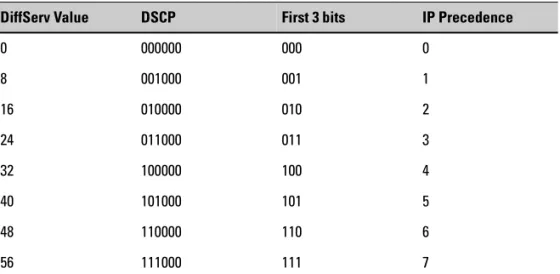
■ Class-Selector PHB—The Class-Selector PHBs provide backward com-patibility with IP precedence. In these PHBs, the last three bits in the DSCP are always set to zero, so only the first three bits (those that match the IP precedence bits) are significant for differentiating the eight classes. Network devices must grant each class the type of service given to the corresponding IP precedence value. Table 8-1 shows the DSCP for the Class-Selector PHB.
Table 8-1. Class-selector PHBs
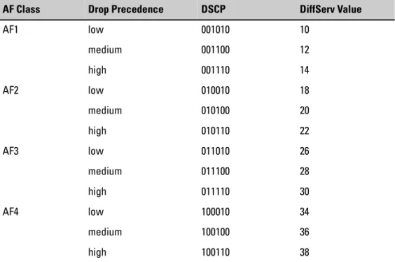
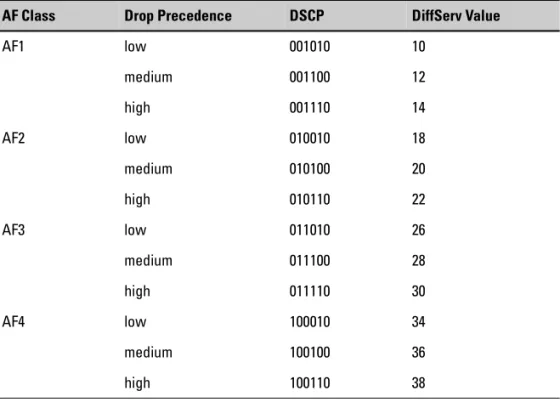
■ Assured Forwarding PHB—The Assured Forwarding PHBs allow you to create four traffic classes (AF1, AF2, AF3, and AF4) and assign different forwarding priorities to each. Values in the first three bits of the DSCP determine the AF class. Several DSCPs match each of the AF PHBs. Within each set of AF PHBs, different DSCPs can define different:
• buffer space • bandwidth • drop precedence
Table 8-2 shows the DSCP for Assured Forwarding PHBs.
DiffServ Value DSCP First 3 bits IP Precedence
0 000000 000 0
8 001000 001 1
16 010000 010 2
24 011000 011 3
32 100000 100 4
40 101000 101 5
48 110000 110 6
Table 8-2. Assured Forwarding PHB
For example, you can define three subclasses with AF1. The third subclass would have a higher drop precedence that the first two. If the AF13 traffic exceeded its limits, the router would drop packets that matched this traffic class, rather than packets from AF12 or AF11. (Note that this means the AF1 class with DSCP 10 receives better service than AF13 with DSCP 14.)
You cannot configure drop precedence or buffer space on the ProCurve Secure Router (although you can mark packets for networks that do consider such specifications). You can configure bandwidth indirectly by assigning certain AF classes a specific proportion of an interface’s band-width with CBWFQ.
■ Expedited Forwarding PHB—The Expedited Forwarding PHB ensures that the packet receives guaranteed bandwidth and the best level of service. This PHB ensures that the traffic has low latency, low jitter, and low loss.
A standard DSCP for the Expedited Forwarding PHB is 46.
On the ProCurve Secure Router, you can configure a low-latency queue for packets marked with the DSCP for the Expedited Forwarding PHB. You should reserve the Expedited Forwarding PHB for mission-critical applications. Using this PHB for a majority or all of the traffic defeats the AF Class Drop Precedence DSCP DiffServ Value
AF1 low 001010 10
medium 001100 12
high 001110 14
AF2 low 010010 18
medium 010100 20
high 010110 22
AF3 low 011010 26
medium 011100 28
high 011110 30
AF4 low 100010 34
medium 100100 36
Only 13 DSCP values have actually been standardized. Individual network administrators define in more detail which set of DSCP values match to a specific PHB. This allows them to use DiffServ with the QoS policies already implemented in a network.
Remember, a PHB simply defines the standard of service that a node should provide for traffic marked for that PHB. DiffServ does not dictate how the node will actually grant such service. Such specifications are left to individual programmers and network administrators.
On the ProCurve Secure Router, you can mark packets with a DSCP, but you cannot define PHB. You can configure the ProCurve Secure Router to: ■ mark a packet with a DSCP for use in the network to which it will be
forwarded
■ read a packet’s DSCP and map it to an IP precedence value to use for WFQ ■ read a packet’s DSCP value and assign it to a class for CBWFQ
■ read a packet’s DSCP value and assign it to a low-latency queue
First In, First Out
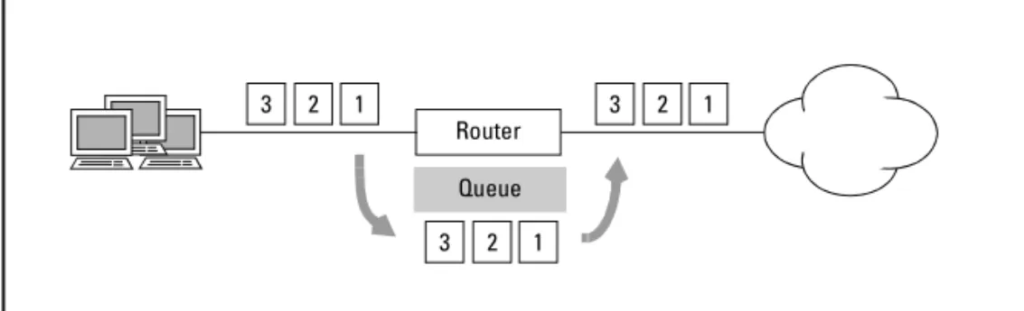
The most basic type of service for packets is First In, First Out (FIFO). A router gives all packets the same best-effort service, forwarding the first packet that arrives on an interface first. (See Figure 8-1.)
When a router uses switched processing to route packets, it forces a packet to wait in the queue until it has completed other CPU processes.
Routers can use fast caching to speed processing for packets that travel often-used routes. When a packet arrives on a fast-cache interface, the router interrupts its other processes to look up a route for the packet in the fast-cache table. This table contains the forwarding interfaces for the destinations of the most recently served packets. If the router does not find a match, it queues the packet as usual. If it does find a match, however, it forwards the packet immediately. Fast caching reduces delay and improves QoS. (Fast caching is enabled by default on the ProCurve Secure Router. For more information about configuring fast caching, see “Fast Caching” on page 11-12 in the Basic Management and Configuration Guide.)
Figure 8-1. First In, First Out
FIFO treats all packets in the same way. If you want the router to take packets’ ToS settings, or other criteria, into account when deciding how to treat them, you must implement a different queuing method.
WFQ
WFQ is one method for granting differentiated service to packets with various ToS values. When an interface uses WFQ, it classifies traffic flow into several conversations, or subqueues, according to source and destination IP addresses and protocol ports. The router then assigns each subqueue a weight according to its IP precedence value and a bandwidth relative to its weight.
CBWFQ
CBWFQ is an extension of WFQ that allows network administrators to define classes of conversation subqueues according to their own criteria. They can also allocate bandwidth to these classes manually. Instead of the router automatically assigning bandwidth to each subqueue based on relative IP precedence, administrators assign each class of subqueue an absolute or a relative amount of bandwidth.
LLQ
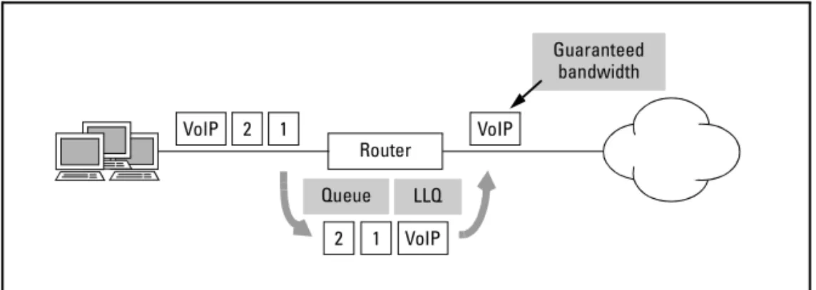
LLQ guarantees a set amount or a set percentage of bandwidth to certain types of traffic. LLQ also ensures that a router serves traffic in the low-latency queue first. (See Figure 8-2.) It is a better solution than WFQ for real-time traffic, such as VoIP, that cannot tolerate jitter or delays.
Router 1
2 3
1 2 3
1 2 3
Figure 8-2. Low Latency Queuing
FRF.12
FRF.12 fragments large data frames so that a Frame Relay interface can forward each frame with less delay. This allows low latency frames, such as VoIP, more opportunities to be forwarded and minimizes delay.
For a more detailed discussion of each of these QoS protocols, see the sections in this chapter on configuring the protocols.
QoS Maps
A QoS map defines QoS policy for an interface on the ProCurve Secure Router. You use it for three functions:
■ define a class for CBWFQ
■ create and define the criteria for a low-latency queue ■ mark packets with an IP precedence or DiffServ value
A QoS map is a list of sequenced entries. Each entry is defined by a name and a sequence number. The name of the map is the name of the map as a whole. The sequence number has two functions:
■ It differentiates entries in the same QoS map—Maps with multiple entries allow you to implement a comprehensive QoS policy on an interface. For example, a single QoS map can establish several low-latency queues. It can also define multiple classes for the traffic sharing the remaining bandwidth using CBWFQ. Each entry defines one low-latency queue or one class.
Guaranteed bandwidth
Router 1
2 VoIP
1 2
LLQ VoIP
VoIP Queue
■ It designates the order in which the ProCurve Secure Router matches traffic to these entries—The ProCurve Secure Router searches QoS entries with the lowest number first. Sequence numbers are only signifi-cant within the named map; QoS maps with different names can have entries with the same sequence number.
Each entry contains match commands and one or more actions. The match command determines the criteria for the class, low-latency queue, or marked packets.
This criteria can be based on: ■ IP precedence or DiffServ value
■ source and/or destination IP address and port (using an extended ACL) ■ destination UTP protocol port
■ bridged traffic
If you specify more than one match command for the QoS map, then traffic must match at least one of the criteria.
The action determines whether the router places matching traffic in a CBWFQ class or low-latency queue. The action can also mark the traffic with a ToS value.
After you create a QoS map, you must assign it to an interface to enable the class, low-latency queue, or packet marking.
Configuring WFQ
Overview
WFQ is one method for granting differentiated service to various types of traffic. It classifies traffic according to the source and destination IP addresses and protocol port, and allocates traffic bandwidth relative to IP precedence value. WFQ is best suited for granting high-priority traffic greater bandwidth. Because WFQ still queues all traffic, it is not best for VoIP and other real-time traffic that cannot tolerate delays.
Conversations
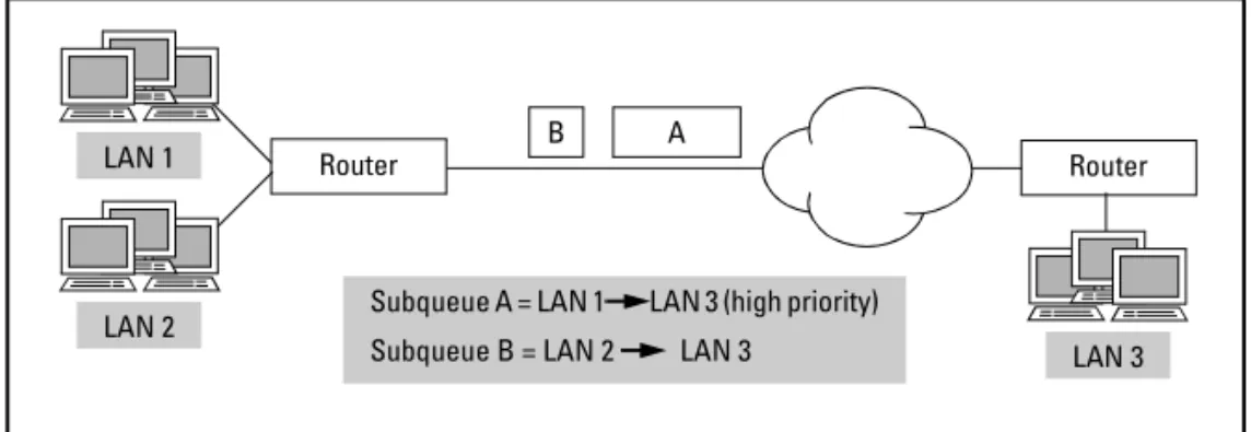
The outbound traffic on a point-to-point connection is the traffic flow. It consists of a queue of packets waiting for service. A router implementing WFQ classifies the traffic flow into several conversations. The router defines each conversation by creating a hash of the source or destination IP address, port number, and protocol type in packets’ IP headers; all packets with the same hash value are in the same conversation.
Figure 8-3. Weighted Fair Queuing
Using WFQ, the router then creates a number of individual subqueues, one for each flow or conversation (see Figure 8-3). The ProCurve Secure Router supports up to 256 conversation subqueues.
Subqueue A = LAN 1 LAN 3 (high priority) Subqueue B = LAN 2 LAN 3
Router LAN 1
LAN 2
B A
LAN 3 Router
Weight
The router also assigns each conversation a weight based on the IP prece-dence value of its packets (see Figure 8-3). The rate at which that conversation gets serviced is proportional to the conversation's assigned weight, preventing weighted interactive traffic such as Telnet from being starved out by high-volume, lower-weighted traffic.
To determine how much bandwidth is allocated to a conversation, the ProCurve Secure Router compares its IP precedence value to the sum of all IP precedence values for conversations on the interface (adding one to these values so that routine traffic is not entirely starved out). WFQ uses the following formula:
(IP precedence value +1)/sum of all (IP precedence values +1)
On the ProCurve Secure Router, WFQ is enabled by default on all WAN interfaces with E1 bandwidth or less. You must set the threshold, or number of packets, allowed in a queue. (By default, the threshold is 64 packets.)
Shortcomings
A closer examination of the formula WFQ uses to allocate bandwidth reveals how WFQ becomes less useful as an interface supports more conversations. First, examine a situation in which WFQ functions well. Most traffic is routine and the interface supports few subqueues. Network control traffic is given IP precedence 7 and traffic to a server is given IP precedence 4. The PPP 1 interface supports 5 queues, three with a precedence of 0, one with 4, and one with 7. When needed, traffic to the server is guaranteed over one-fourth of the bandwidth and network control traffic is guaranteed half. Traffic with a higher precedence receives relatively more bandwidth. (See Table 8-3.)
Table 8-3. WFQ Example 1
Subqueue Precedence Precedence + 1 Weight
1 0 1 .0625
2 0 1 .0625
3 0 1 .0625
4 4 5 .312
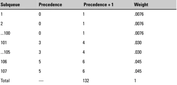
Now, consider an interface that handles more conversations at once—for example, 100 routine subqueues, 5 subqueues with a precedence of 3, and 2 queues for VoIP traffic with a precedence of 5. Even though VoIP traffic receives relatively more bandwidth than any individual routine subqueue, routine traffic altogether consumes 75 percent of the bandwidth. Neither VoIP queue is guaranteed even 5 percent of the total bandwidth. (See Table 8-4.) In addition, even though some subqueues receive relatively more bandwidth, all traffic must wait in queues. This level of service is inadequate for real-time traffic such as VoIP, which requires low latency and jitter.
Table 8-4. WFQ Example 2
Packet Marking
WFQ allocates bandwidth to conversation subqueues according to the IP precedence value in the IP headers of packets in the subqueue. The higher the value, the greater the bandwidth the queue is given. In order for WFQ to function, therefore, packets must somehow be marked with this value. Packets can be marked:
■ by an application or other device outside the router (typically, packet marking is most effective when it is implemented near the edge) ■ by the ProCurve Secure Router
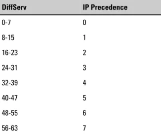
The router can also recognize DiffServ values, but it does not grant differen-tiated service for each DiffServ value. Instead, it maps several DiffServ values to a single IP precedence value and then treats the traffic as if it were marked with that value. (See Table 8-5.)
Subqueue Precedence Precedence + 1 Weight
1 0 1 .0076
2 0 1 .0076
...100 0 1 .0076
101 3 4 .030
...105 3 4 .030
106 5 6 .045
107 5 6 .045
Table 8-5. Mapping DiffServ to IP Precedence
If applications and devices outside the router will handle all packet marking, you only need to enable WFQ and set a threshold level for subqueues. If you want the router itself to mark packets with an IP precedence or DiffServ value, you must configure a QoS map to do so. You would then apply this map to a WAN interface. The router will mark matching outgoing packets with the value you set. To learn how to configure the ProCurve Secure Router to mark packets, see “Marking Packets with a ToS value” on page 8-45.
Enabling WFQ
WFQ is automatically enabled on all interfaces with E1 bandwidth or less. You enable WFQ on the logical, rather than the physical, interface. For Frame Relay, the interface, rather than the subinterface, handles queuing; however, you enable WFQ on Asynchronous Transfer Mode (ATM) subinterfaces. To enable or disable WFQ, move to the configuration mode context for that interface and enter:
Syntax:[no] fair-queue [<threshold value>]
If you disable WFQ, the ProCurve Secure Router will use FIFO queuing for that interface.
DiffServ IP Precedence
0-7 0
8-15 1
16-23 2
24-31 3
32-39 4
40-47 5
48-55 6
Specifying the threshold when you enable WFQ is optional. The threshold determines the maximum number of packets the interface can hold in each conversation subqueue. When the queue reaches this limit, the ProCurve Secure Router discards any subsequent packets it receives. You can specify a threshold from 16 to 512 packets. For example:
ProCurve(config-fr 1)# fair-queue 256
The default threshold is 64.
Setting the Queue Size
You can also specify how many packets an interface can hold in all conversa-tion subqueues together. Enter:
Syntax:hold-queue <packets> out
You can set the limit between 16 and 1000. The default number of packets that WFQ interfaces can hold is 400.
The ProCurve Secure Router also uses this setting with interfaces that imple-ment FIFO queuing. The hold queue size is the maximum number of packets in the interface’s single queue and, so, the limit for the interface. The default number of packets that FIFO can hold is 200.
Configuring CBWFQ
Overview
CBWFQ is an extension of WFQ that allows you to tailor a QoS policy to your organization’s needs. With CBWFQ, you control:
■ how traffic is divided into conversation subqueues ■ how much bandwidth is allocated to each subqueue
You exercise this control by defining classes. For each class, you specify the traffic matching criterion and set a minimum guaranteed bandwidth. Each interface implementing CBWFQ supports up to four classes.
WFQ automatically classifies traffic into conversations according to source and destination IP address, port number, and protocol type. With CBWFQ, you manually configure how traffic is classified. You define a class according to IP header fields, and the interface places all traffic that fits that definition into the same subqueue.
WFQ only looks at IP precedence to determine the bandwidth to allocate each subqueue. With CBWFQ, you can specify the bandwidth for a class’s subqueue as an absolute value or as a percentage. The bandwidth is the minimum guaranteed to the class; it may burst above this value. You can reserve up to 75 percent of the interface’s bandwidth for all CBWFQ classes together. Traffic that does not fall within a defined class is divided into subqueues using typical WFQ, and is allocated its share of whatever remains of the connection’s bandwidth. Because classes may burst above their guaranteed bandwidth, other traffic may be starved out of the connection.
Configuring Classes for CBWFQ
When you configure CBWFQ on the ProCurve Secure Router, you must configure:
■ the criterion for a class
■ the absolute or relative bandwidth allocated to each class
On the ProCurve Secure Router, you define classes for CBWFQ in a QoS map entry.
To configure CBWFQ, you must complete these steps: 1. Create a QoS map entry.
2. Define a class. You can define classes according to: • ToS value
• IP header fields—source and destination IP address, port, and protocol
• destination UDP protocol port • bridged protocol
3. Allocate bandwidth to the class.
4. Create QoS map entries with the same name and different sequence numbers to configure multiple classes. Repeat steps 2 and 3.
5. Apply the QoS map to a WAN interface.
Creating a QoS Map Entry
To create a QoS map, enter the following command from the global configu-ration mode context:
Syntax:qos map <mapname> <sequence number>
The mapname is alphanumeric and case-sensitive. Valid sequence numbers range from 0 to 65,535.
If you are using LLQ and CBWFQ on the same interface, the map entries for the low-latency queues and the CBWFQ classes should use the same name. For example, you could use map entries 0 and 1 for low-latency queues and configure map entry 2 to define a CBWFQ class:
ProCurve(config)# qos map QoSMap 2
N o t e
The router matches packets to lower-numbered entries first. If you configure classes that might match the same traffic, you should assign the entry for the more specific definition a lower sequence number.Using different kinds of criteria to define classes on the same interface can also complicate matters. For example, a packet might fall into a class of traffic from subnet 192.168.3.0 and into a class of traffic with IP precedence 4. You should either use the same kind of criteria for all the classes or take care to assign a lower sequence number to the entry you want to take precedence in defining traffic.
Defining a Class
You define a class by matching the QoS map entry to packets that meet certain criteria.
Table 8-6. QoS Map Criteria
Each QoS map entry can use only one set of criteria to match traffic. To match another group of traffic, you must configure another entry.
Enter one of the match commands shown in Table 8-6 to select traffic. Different options for the match command will be discussed separately in the following sections.
Classifying Traffic According to a ToS Value. WFQ allocates relatively more bandwidth to traffic with higher IP precedence (or DiffServ values). Simple WFQ must use this formula:
(IP precedence value +1)/sum of all (IP precedence values +1)
With CBWFQ, you can control how much bandwidth the router assigns to a class defined by a ToS value.
You would create an entry for each ToS value your system uses and then enter this command:
Syntax:match [dscp <value> | precedence <value>]
Valid DiffServ (DSCP) values are from 0 to 63; valid IP precedence values are from 0 to 7. For example:
ProCurve(config-qos-map)# match precedence 5
Criteria Match Command
ToS value—IP precedence match precedence <0-7> ToS value—DiffServ match dscp <0-63> IP header—source or destination IP
address and protocol port
match list <ACL listname>
destination UDP protocol port match ip rtp <first port number> [<last port number>] [all]
N o t e
This ToS value is set by an application or device before the packet arrives on the interface. Although the router can mark traffic with ToS values, these values are generally used in the network to which the router forwards the packet.DiffServ defines four classes of AF PHB, each class receiving successively better service. (The first subclass in an AF class receives better treatment because it has a lower drop precedence.) You could configure four classes to match four AF PHB and allocate each successive class relatively more band-width. (See Table 8-7 for the DSCP for AF PHB.)
Table 8-7. Example of Assured Forwarding PHB
AF Class Drop Precedence DSCP DiffServ Value
AF1 low 001010 10
medium 001100 12
high 001110 14
AF2 low 010010 18
medium 010100 20
high 010110 22
AF3 low 011010 26
medium 011100 28
high 011110 30
AF4 low 100010 34
medium 100100 36
You would enter these commands to match classes to the four simple AF PHBs:
ProCurve(config)# qos map Class 11 ProCurve(config-qos-map)# match dscp 10 ProCurve(config)# qos map Class 12 ProCurve(config-qos-map)# match dscp 18 ProCurve(config)# qos map Class 13 ProCurve(config-qos-map)# match dscp 26 ProCurve(config)# qos map Class 14 ProCurve(config-qos-map)# match dscp 34
This example only shows how to define what traffic is placed in the class. When actually configuring CBWFQ, you would set the bandwidth for the class at the same time. See “Allocating Bandwidth to a Class” on page 8-26. Classifying Traffic According to IP Header Fields. You can classify packets according to the fields in their IP headers—that is, according to their source and destination IP addresses, port number, and protocol. This method of classifying traffic mimics simple WFQ. However, you can place traffic to and from an entire range of addresses in the same class. One of the
shortcomings of WFQ is that the more subqueues an interface supports, the less that interface can grant higher priority subqueues significantly greater bandwidth. Dividing traffic into a small number of classes alleviates this problem.
You classify traffic in this way by matching the QoS map entry to an extended access control list (ACL). The ACL actually selects the traffic. An extended ACL can define traffic according to its source and destination IP address, as well as a variety of fields in the IP, TCP, or UDP headers.
To classify traffic: 1. Configure an ACL.
a. Create an extended ACL—QoS maps can only use extended ACLs. b. Add any necessary deny entries to the ACL.
c. Add permit entries for the source and/or destination addresses of traffic in the class.
2. Match the QoS map entry to the ACL.
Configuring an ACL. Create an ACL by entering this command from the global configuration mode context:
For example:
ProCurve(config)# ip access-list extended ClassSelector
ACLs exclude all traffic that you do not explicitly permit, so you may not need to enter any deny statements. However, you will often permit an entire range of addresses. If you want to deny a host or hosts within this range, you must explicitly deny those hosts. You must enter the deny statements first because the router processes ACL entries in order and stops processing them as soon as it finds a match.
You use this command to select traffic in the ACL:
Syntax:[deny | permit] ip [any | host <source A.B.C.D> | <source A.B.C.D> <wildcard bits>] [any | host <destination A.B.C.D> | <destination A.B.C.D> <wildcard bits>]
Very often, you will want an ACL to select an entire range of addresses or subnets. ACLs on the ProCurve Secure Router use wildcard bits (which operate on reverse logic from subnet masks) to select a range of addresses. You can also select certain types of traffic (for example, HTTP or Telnet) by specifying a protocol such as TCP or UDP and then indicating the source or destination port after the address:
Syntax:[deny | permit] <protocol> [any | host <A.B.C.D> | <A.B.C.D> <wildcard bits>] [any | eq <port> | gt <port> | lt <port> | range <first port> <last port> | neq <port> | host <port>] [any | host <A.B.C.D> | <A.B.C.D> <wildcard bits>] [any | eq <port> | gt <port> | lt <port> | range <first port> <last port> | neq <port> | host <port>]
For example:
ProCurve(config-ext-nacl)# permit tcp host 192.168.4.1 eq telnet any
The eq keyword selects a single port and the range keyword allows you to enter a range of ports. You can specify the port by number, or for well-known protocols, by keyword. Use the ? help command to get a complete list of keywords. For example:
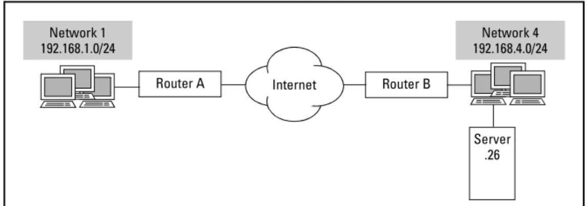
Figure 8-4. Classifying Network Traffic
In Figure 8-4, Network 1 at site A transmits mission-critical data to network 4 at site B. Host 26 on network 4 is a local DHCP server; it does not need to receive this critical data. To select the traffic for the class, you would enter:
ProCurve(config)# ip access-list extended ClassSelector ProCurve(config-ext-nacl)# deny ip any host 192.168.4.26
ProCurve(config-ext-nacl)# permit ip 192.168.1.0 0.0.0.255 192.168.4.0 0.0.0.255
You could configure another ACL that will be used to define a class for Web traffic:
ProCurve(config)# ip access-list extended WebTraffic ProCurve(config-ext-nacl)# permit tcp any any eq www
For more information about configuring ACLs, see Chapter 5: Applying Access Control to Router Interfaces.
Matching a QoS Map Entry to an ACL. Move to the configuration mode context for the QoS map entry you have created. Then enter this command: Syntax:match list <ACL listname>
For example:
ProCurve(config)# qos map Class 15
ProCurve(config-qos-map)# match list ClassSelector
Classifying Traffic According to Destination UDP Port. Different applications require different levels of service. You can group similar applica-tions together into a class according to their destination UDP port and then grant that class a certain portion of the interface’s bandwidth.
Internet Router A
Network 1 192.168.1.0/24
Server .26 Router B
Network 4 192.168.4.0/24
You use this command:
Syntax:match ip rtp <first port number> <last port number> [all]
Thematch ip rtp command configures the router to match all UDP packets destined to even port numbers in the specified range. (Typically, servers listen for user traffic on even ports.) If you want to match traffic to both even and odd ports, you must add the all keyword.
You can use this command to define a CBWFQ class; however, this command selects real-time traffic, for which you should generally configure a low-latency queue. See “Placing Traffic in a Low-Latency Queue” on page 8-37. Classifying Bridged Traffic. You can configure one or more interfaces on a the ProCurve Secure Router to act as a bridge. In effect, the router extends a LAN throughout two or more remote sites. Traffic between hosts at each local site can obviously travel faster than that between hosts at different sites. Local hosts are not only physically closer, but they can also take advantage of higher-speed Ethernet connections.
Often, an interface will bridge all traffic. However, a Frame Relay interface may carry one subinterface that routes traffic and one that bridges traffic. You can define bridged traffic as a class and set the maximum bandwidth that class is guaranteed.
To place all bridged traffic in a class, enter:
ProCurve(config-qos-map)# match protocol bridge
Instead of placing all bridged traffic in a class, you can place only NetBIOS Extended User Interface (NetBEUI) traffic. NetBEUI allows hosts to commu-nicate within the LAN. You can define such traffic as a class of its own. For example:
ProCurve(config)# qos map Class 12
ProCurve(config-qos-map)# match protocol bridge netbeui
Allocating Bandwidth to a Class
You can allocate bandwidth for classes with absolute or relative values. For example, you define three classes on an interface with a 2 Mbps connection. You could allocate 500 Kbps to one class, 250 to another, and 200 to the last. Or you could allocate 25 percent of the bandwidth to one class, 12 percent to another, and 10 percent to the last. The ProCurve Secure Router allows you to reserve up to 75 percent of an interface’s bandwidth for all classes together.
If you have configured one or more low-latency queues on the interface, you might want to divide the remaining bandwidth rather than the total band-width. This option eases the configuration process; you do not have to figure out how much bandwidth must be reserved for the low-latency queues. You assign a class its bandwidth from the configuration mode for the QoS map entry that defines it. You must specify bandwidth in the same way (absolute, percentage, or remaining percentage) for each class in the QoS map.
To specify the maximum bandwidth guaranteed to the queue, move to the QoS map entry for the class and enter:
Syntax:bandwidth [<Kbps> | percent <percentage> | remaining percent <percentage>]
For example, to set the bandwidth as an absolute value, enter:
ProCurve(config-qos-map)# bandwidth 500
To specify bandwidth as a percentage of total bandwidth, use the percent keyword:
ProCurve(config-qos-map)# bandwidth percent 25
The percent keyword calculates bandwidth from the total available band-width on an interface. The total available bandband-width is the access rate for Point-to-Point Protocol (PPP) and High-level Data Link Control (HDLC) inter-faces and for ATM subinterinter-faces. The total available bandwidth is the rate-limited bandwidth for Ethernet and Frame Relay interfaces. However, you can only allocate up to 75 percent of the available bandwidth to queues.
To specify bandwidth as a percentage of the bandwidth not allocated to low-latency queues, use the remaining percent keyword. The remaining per-cent keyword calculates bandwidth from the amount remaining after the bandwidth guaranteed to low latency queues has been subtracted from the available bandwidth. Unlike commands using the percent keyword, this command does not subtract bandwidth from the bandwidth available for the low-latency queues.
N o t e
The bandwidth available for queues on a ProCurve Secure Router is 75 percent of an interface’s access rate or rate-limited rate. The Secure Router OS will deactivate a QoS map when you assign it to an interface that does not have enough bandwidth available to grant the guaranteed rate.Other traffic can use the remaining 25 percent of the bandwidth, although this traffic may also be starved out by traffic in a class bursting past its guaranteed level.
The router automatically provides bandwidth for control traffic such as routing updates; control traffic takes priority over all classes.
Traffic that does not fit into one of the classes you have defined is served with typical WFQ. It is divided into conversation subqueues according to source and destination IP addresses and port, and is allocated a portion of the remaining bandwidth based on its IP precedence value.
Specifying Bandwidth by Remaining Percent Versus Percent. For example, you limit an Ethernet interface’s rate to 10 Mbps. You guarantee at least 4 Mbps to low-latency queues. You then assign one class 25 percent of the remaining bandwidth and another class 15 percent of the remaining bandwidth. Subtracting 4 Mbps from 10 Mbps leaves 6 Mbps. The first class receives 1.5 Mbps and the second, 900 Kbps. The bandwidth required for the map is 6.4 Mbps. The bandwidth available for queues is 75 percent of the rate limited bandwidth, or 7.5 Mbps. The map can become active.
Now, consider how much bandwidth the classes would receive if you config-ured the QoS map using the percent keyword rather than the remaining percent keyword. The first class would receive 25 percent of 10 Mbps, or 2.5 Mbps. The second class would receive 15 percent of 10 Mbps, or 1.5 Mbps. With the low-latency queues, the bandwidth required for the map is 8 Mbps. Because queues can only consume up to 7.5 Mbps on the Ethernet interface, the router would force the map to become inactive. You would have to reconfigure the QoS map.
Assigning the QoS Map to an Interface
You must create a separate QoS map entry for each class you want to define, giving each entry the same name but a different sequence number. You can define up to four classes. You can also implement low-latency queues on the same interface. Simply create an entry for these queues in the same QoS map. (See “Configuring LLQ” on page 8-32.)
Next, apply the QoS map to the logical interface for the connection on which you want to enable CBWFQ. Move to the interface configuration mode context and enter:
Syntax:qos-policy out <mapname>
For example:
ProCurve(config)# interface frame-relay 1 ProCurve(config-fr 1)# qos-policy out Class
Special Considerations for CBWFQ with Multilinks
Multilink protocols such as Multilink PPP (MLPPP) and Multilink Frame Relay (MLFR) increase the total bandwidth of a connection. Although the bundle of carrier lines acts as a single logical connection, each carrier line is physically separate, and you should remember this as you allocate the interface’s band-width. Carrier lines may go down and alter the bandwidth actually available. For example, an MLPPP connection with two T1 lines provides 3.0 Mbps of bandwidth. You can allocate up to 75 percent of this bandwidth, or 2.25 Mbps, to the interface’s classes. You could allocate 300 Kbps (10 percent) to Class 1, 600 Kbps (20 percent) to Class 2, 600 Kbps to Class 3, and 750 Kbps (25 percent) to Class 4. However, if one of the lines fails, the connection will only have 1.5 Mbps of bandwidth to provide the 2.25 guaranteed. If Class 3 and Class 4 are already consuming their full minimum bandwidth (1.35 Mbps), traffic from Class 2 will not be able to receive its guaranteed level of service.
You should consider allocating bandwidth to the multilink connection as if it had one carrier line less than the total. This is particularly true when the multilink is designed more to provide redundancy than to increase a connec-tion’s bandwidth.
N o t e
Even when you assign bandwidth to classes as a percentage, the router assigns it as an absolute value of the bandwidth normally available on the interface. This means that when one or more lines in a multilink bundle goes down, the router does not automatically readjust the bandwidth allocated to various classes.CBWFQ Example Configuration
In Figure 8-5, Site A includes two networks that connect to the Internet. It also connects to remote Site B through a virtual private network (VPN). Your organization does not want Internet traffic to starve out traffic to the remote site. You can configure CBWFQ to reserve at least 25 percent of the bandwidth for Network 1 to access the remote site and 20 percent for Network 2. Site A also includes the company Web server. Company policy dictates that 15 percent of the bandwidth must be reserved for traffic from the server.
Figure 8-5. CBWFQ Example Configuration You would implement this policy as follows: 1. Configure the ACLs to select VPN traffic:
a. Match traffic from Network 1 and 2 to Site B:
ProCurve(config)# ip access-list extended Network1
ProCurve(config-ext-nacl)# permit ip 192.168.1.0 0.0.0.255 192.168.16.0 0.0.15.255
ProCurve(config)# ip access-list extended Network2
ProCurve(config-ext-nacl)# permit ip 192.168.2.0 0.0.0.255 192.168.16.0 0.0.15.255
b. Match traffic from the Web server:
ProCurve(config)# ip access-list extended WebTrafficOut
ProCurve(config-ext-nacl)# permit tcp host 192.168.1.26 eq www any
Router A Network 1
192.168.1.0/24
Web Server .26
Router B
Network 3 192.168.17.0/24
Network 4 192.168.20.0/24 Internet
Network 2 192.168.10.0/24
Site B 192.168.16.0/20
2. Match the ACLs to the classes and set the bandwidth for each:
a. First, define the class for traffic from the Web server. Set the entry number lower than that for the class for Network 1 traffic so that the router does not inadvertently match traffic from the server to the wrong class:
ProCurve(config)# qos map Class 10
ProCurve(config-qos-map)# match list WebTraffic Out ProCurve(config-qos-map)# bandwidth percent 15
b. Define the classes for VPN traffic from the local networks to the remote sites:
ProCurve(config)# qos map Class 11
ProCurve(config-qos-map)# match list Network1 ProCurve(config-qos-map)# bandwidth percent 25 ProCurve(config)# qos map Class 12
ProCurve(config-qos-map)# match list Network2 ProCurve(config-qos-map)# bandwidth percent 20
N o t e
The QoS map entries for the classes started at 10 to leave room for low-latency queues. For example, employees at Sites A and B might use VoIP phones. Because voice traffic needs particularly low delay service, you could configure a low-latency queue for such traffic in map entry Class 1. Assigning this entry a lower sequence number prevents voice packets that match other entries from being placed in the wrong queue.3. Assign the QoS map to the PPP interface that connects to the Internet:
ProCurve(config)# interface ppp 1
Configuring LLQ
Overview
LLQ is a method for guaranteeing a set amount of bandwidth to certain traffic and reducing this traffic’s latency. You should use LLQ for voice and other real-time applications that involve traffic that cannot tolerate excessive or variable delay (jitter).
When a packet that matches the criteria for a low-latency queue arrives on an interface, the router immediately places it in this queue. The low-latency queue is always served first and is always given bandwidth up to the guaranteed level. Low-latency traffic can also burst past its guaranteed level when bandwidth is available. You can specify an upper limit for bursting low-latency traffic to prevent it from entirely starving out other traffic.
Packets that do not match the criteria for the low-latency queue are served by the queuing method enabled on the interface (FIFO or CBWFQ) with the remaining bandwidth.
When you configure a low-latency queue on the ProCurve Secure Router, you must configure:
■ the criteria for packets placed in the queue ■ the bandwidth guaranteed the queue
Determining Bandwidth for the Queue
LLQ allows you to manually determine the bandwidth a queue receives. Before you configure a low-latency queue, you should plan for every queue that will be implemented on the interface. You can then determine how much band-width to assign each queue. If the interface also implements CBWFQ, you should remember to take bandwidth allocated to classes into account. This section of the guide gives you some general guidelines for determining how much bandwidth you must allocate to:
■ VoIP traffic ■ video streams
You should, of course, refer to the documentation for your VoIP application and follow any instructions given in that documentation first.
Determining Bandwidth for VoIP
One of the most common applications for a low-latency queue is VoIP traffic. You calculate the bandwidth necessary for VoIP traffic by:
1. calculating the bandwidth necessary for one call
2. making adjustments to this calculation according to the capabilities of your VoIP devices
3. multiplying the per-call bandwidth by the number of calls the router needs to support at once
Calculating Per-Call Bandwidth. VoIP standards specify the minimum bit rate necessary for acceptable voice quality. Various standards specify various rates. (See Table 8-8.)
However, this rate does not correspond exactly to the bandwidth necessary to maintain voice quality. The rate is that for voice bits, but, because frame and packet headers add overhead, a connection must provide greater band-width. VoIP packets are quite small; headers might add as many, or even more, bytes than the payload of actual voice data.
To calculate the per-call bandwidth for your VoIP application, you must transform its specified bit rate into a rate of packets per second. This rate depends on the size of the voice payload, which in turn depends on the codec your system’s application uses.
Table 8-8. VoIP Standards
Standard Bit Rate Codec (Sample Time) Sample Size Packets Per Second
G.711 • 56 Kbps
• 64 Kbps
20 ms • 140 bytes
• 160 bytes
50
G.722 • 48 Kbps
• 56 Kbps • 64 Kbps
20 ms • 120 bytes
• 140 bytes • 160 bytes
50
G.723.1 • 5.3 Kbps • 6.3 Kbps
30 ms • 20 bytes
• 24 bytes
The codec dictates how often the voice stream is sampled, and together with the bit rate, the size of each voice sample. For example, G.722 has a 20 ms codec and 64 Kbps rate. Therefore, each sample is 160 bytes. (64,000 bits/ second x .02 seconds = 1280 bits. 1280 bits/8 = 160 bytes.) This sample size is relatively large. Others, however, are very small. For example, a G.729 sample size might be only 10 bytes.
N o t e
The voice payload for VoIP packets is divisible by the sample size. Some VoIP applications combine several samples into a single packet to reduce overhead. For example, G.728 packets often include four samples.Calculate the packets transmitted per second by dividing the bit rate by the number of bits (not bytes) in the total voice payload. The router must forward this many frames across the WAN connection every second to maintain an acceptable QoS.
To determine how much bandwidth the router needs to forward the required number of frames per second, first calculate the total size of a frame. Add the number of bits in the frame and packet headers to the number of bits in the voice payload. Then multiply the total size of the frames in bits by the rate of packets per second. This is the minimum bandwidth required per call over the WAN connection.
Table 8-9 shows example calculations for common sample sizes with several VoIP standards.
G.728 16 Kbps 2.5 ms • 5 bytes
• often more than one sample per packet— for example, 4 samples per packet for 20 bytes
100
G.729 8 Kbps 10 ms • 10 bytes
• often more than one sample per packet— for example, 2 samples per packet for 20 bytes
50
Table 8-9. Example Bandwidth Calculations for VoIP
The necessary bandwidth depends on:
■ The size of the packet headers—Packet headers are 47 bytes for MLPPP and MLFR connections as well as Frame Relay connections that use fragmentation:
• 20 for the IP header • 8 for the UDP header • 12 for the RTP header
• 6 for the MLPPP or MLFR header
• 1 for the MLPPP or MLFR end-of-frame flag
If you use the MLPPP long sequence number format, the MLPPP header is 8- bytes and the total size for packet headers is 49 bytes. For PPP connections, the packet headers are 45 bytes.
Real-time Transport Protocol (RTP) compression (cRTP) reduces the IP header from 40 bytes to 2 bytes (or 4 bytes with checksums), which decreases necessary bandwidth.
■ The size of the voice payload—Each packet must have a set number of bytes in its header no matter how large or how small its payload. As the size of the voice payload increases, the proportion of bytes consumed in overhead decreases and so does the necessary bandwidth. Combining several samples in the same packet increases the size of the voice payload. However, the decrease in required bandwidth comes at the price of higher latency.
Standard Packets per Second Voice Payload Size Total Size with MLPPP or Frame Relay header
Per-Call Bandwidth
G.711 50 • 140 bytes
• 160 bytes
• 187 bytes • 207 bytes
• 74.8 Kbps • 82.8 Kbps
G.722 50 • 120 bytes
• 140 bytes • 160 bytes
• 167 bytes • 187 bytes • 207 bytes
• 66.8 Kbps • 74.8 Kbps • 82.8 Kbps
G.723.1 33.3 • 20 bytes
• 24 bytes
• 67 bytes • 71 bytes
• 17.8 Kbps • 18.9 Kbps
G.728 100 20 bytes 67 bytes • 53.6 Kbps
Making Adjustments. Calls typically contain bursts of noise when a person speaks and periods of silence when the person listens. Some VoIP applications use Voice Activity Detection (VAD) to suppress transmission of VoIP frames when the line is silent. If your equipment uses VAD, you can cut the per-call bandwidth requirement by as much as half.
Calculating Total Bandwidth. Your organization should study typical VoIP usage patterns. It should then generate a policy for the number of calls the router should support at once, taking into account cost and other needs for bandwidth.
Multiply the minimum number of calls the WAN must support by the per-call bandwidth.
This is the bandwidth you would specify for the VoIP low-latency queue. (See “Setting the Bandwidth Guaranteed the Queue” on page 8-42.)
Determining Bandwidth for Video Streaming
Organizations are increasingly using videoconferencing to broadcast com-pany presentations and to allow employees at remote sites to communicate. Like VoIP, video streaming requires low jitter. Video packets are larger than VoIP packets and so require much more bandwidth and have a larger serial-ization delay. However, streaming video tends to be less interactive than voice, so the traffic can tolerate higher delay. Many applications hold the initial video packets and send the streaming video with a continual lag so that, overall, the video runs smoothly without jitter or delay.
Because the packets are relatively large, overhead from frame and packet headers does not greatly increase required bandwidth.
Several H.323 and Session Initiation Protocol (SIP) standards have emerged for video. The amount of bandwidth required depends on the resolution and the number of frames per second and can be very large. Even though com-pression greatly reduces required bandwidth, the router may need to devote a large portion of a T1 or E1 line to a video stream while it is active.
The video application should indicate minimum bit rates for different quality pictures. Determine the number of video streams the router must be able to establish at once and multiply it by the bit rate you select. The video streamer may also send the video to a Web server, which all hosts can access.
Placing Traffic in a Low-Latency Queue
The ProCurve Secure Router guarantees traffic in a low-latency queue the amount of bandwidth you specify. Traffic can burst above this bandwidth, but if the line becomes congested, the router will drop bursting packets in favor of other traffic.
The QoS map entry both selects traffic for the queue and assigns the queue a bandwidth.
To configure LLQ, you must complete these steps: 1. Create a QoS map entry.
2. Match the entry to traffic that meets your criteria. 3. Set the queue’s maximum guaranteed bandwidth. 4. Apply the QoS map to a WAN interface.
You can place the following traffic in a low-latency queue: ■ traffic marked with a certain ToS value
■ traffic with a certain source and/or destination IP address and port ■ traffic destined to a certain range of UDP protocol ports
■ bridged traffic
Creating a QoS Map Entry
To create a QoS map, enter the following command from the global configu-ration mode context:
Syntax:qos map <mapname> <sequence number>
The sequence number indicates the priority for the QoS map entry. Because the ProCurve Secure Router searches entries with the lowest numbers first, the lower the map’s number, the higher its priority. For example, enter:
ProCurve(config)# qos map LowLatency 10
Selecting the Traffic to Be Placed in the Low-Latency Queue
You select the traffic that the QoS map entry will mark by entering one of the match commands shown in Table 8-10.
Table 8-10. QoS Map Criteria
Each QoS map entry can use only one set of criteria to match traffic. To match another group of traffic, you must configure another entry.
Placing Traffic with a Certain ToS Value in a Low-Latency Queue. WFQ allocates more bandwidth to traffic with higher IP precedence or Diff-Serv values. However, the more conversation subqueues an interface accumu-lates, the less effect a high ToS value has. Rather than relying on packets’ ToS values to grant them the bandwidth they need, you can place packets with a certain ToS value in a low-latency queue. Use this command:
Syntax:match [dscp <value> | precedence <value>]
Use the dscp option to select DiffServ values. Valid DiffServ values are from 0 to 63; valid IP precedence values are from 0 to 7.
For example, for VoIP traffic you would enter the value set by your VoIP devices. Usually, this is the DiffServ value for Expedited Forwarding (46). Enter:
ProCurve(config-qos-map)# match dscp 46
You can only match the entry to one value. If you want to match more than one value, you must configure another entry for the QoS map.
N o t e
The ToS value for LLQ is always set by an application or device before the packet arrives on the interface. Although the router can mark traffic with ToS values, these values are used in the network to which the router forwards the packet.Criteria Match Command
ToS value—IP precedence match precedence <0-7> ToS value—DiffServ match dscp <0-63> IP header—source or destination
IP address and protocol port
match list <ACL listname>
destination UDP protocol port match ip rtp <first port number> [<last port number>] [all] bridged traffic match protocol bridge [netbeui]
Placing Traffic Destined to a UDP Protocol Port in a Low-Latency Queue. VoIP and other real-time traffic requires special handling. Congestion affects this traffic far more negatively than it does bursty data traffic. One way of classifying VoIP traffic is noting the UDP ports on which your VoIP appli-cations operate. You can then match a QoS map entry to these ports. You can, of course, similarly define low-latency queues for other applications.
You use the match ip rtp command to place RTP packets destined to a range of UDP destination ports in a low-latency queue:
Syntax: match ip rtp <first port number> <last port number> [all]
For example, RTP applications generally operate between ports 16,384 and 32,767. You would enter:
ProCurve(config-qos-map)# match ip rtp 16384 32764 all
N o t e
The router matches all RTP packets destined to even port numbers in the specified range. (Typically, servers listen for traffic on even ports.) If you want to match traffic to both even and odd ports, you must add the all keyword. Placing Traffic to and/or from an IP Address in a Low-Latency Queue. You can assign packets to a low-latency queue according to the source and/or destination IP addresses in their IP headers.You can guarantee all traffic from a network—for example, a subnet that transmits mission-critical data—low latency. You may also want to give pack-ets destined to a specific address a set amount of bandwidth. For example, you can prioritize traffic to the router’s Web browser interface, so that IT staff can manage the router despite network congestion.
You place such traffic in a queue by matching the QoS map entry to an ACL. The ACL actually selects the traffic. An extended ACL can define traffic according to its source and destination IP address as well as a variety of fields in the IP, TCP, or UDP header.
To place traffic with certain values in its IP header in a low-latency queue, you must:
1. Configure an ACL.
a. Create an extended ACL.
b. Add any necessary deny entries to the ACL.
c. Add permit entries for the addresses to or from which you want to guarantee traffic bandwidth.
Configuring an ACL. Create an ACL by entering a command such as this from the global configuration mode context:
ProCurve(config)# ip access-list extended LowLatencyTraffic
ACLs exclude all traffic that you do not explicitly permit, so you may not need to enter any deny statements. However, you must explicitly deny traffic to or from a denied host within a permitted range—for example, host 99 on the permitted 192.168.3.0 /24 subnet. You must enter the deny statements first because the router processes ACL entries in order and stops processing them as soon as it finds a match.
You will often want an ACL to select an entire range of addresses or subnets. ACLs on the ProCurve Secure Router use wildcard bits (which operate on reverse logic from subnet masks) to select ranges of addresses.
You use this command to select traffic to be matched or not matched: Syntax:[permit | deny] ip [any | <source A.B.C.D> <wildcard bits> | host <source A.B.C.D>] [any | <destination A.B.C.D> <wildcard bits> | host <destination A.B.C.D>]
Wildcard bits operate on opposite logic from subnet masks. A one means that the router ignores that bit when deciding whether a packet’s source or destination address matches the entry. For example, if you wanted to select every host in a Class B network, you would use the wildcard bits 0.0.255.255.
Figure 8-6. Placing Network Traffic in a Low-Latency Queue
PPP1 LLQ Router A Network 1 VoIP
172.16.1.0/24
Server .26
Router B
Network 4 172.16.4.0/24
Network 1 at Site A, shown in Figure 8-6, contains VoIP equipment that communicates with equipment at Network 4 at Site B. Host 26 on Network 1 is an email server; it does not send real-time data. To select the traffic to be placed in a low-latency queue, enter:
ProCurve(config)# ip access-list extended LowLatencyTraffic ProCurve(config-ext-nacl)# deny ip host 172.16.1.26 any
ProCurve(config-ext-nacl)# permit ip 172.16.1.0 0.0.0.255 172.16.4.0 0.0.0.255
You can also select certain types of traffic (for example, HTTP or Telnet) by specifying a protocol such as TCP or UDP and then indicating the source or destination port after the address:
Syntax:[deny | permit] <protocol> [any | host <A.B.C.D> | <A.B.C.D> <wildcard bits>] [any | eq <port> | gt <port> | lt <port> | range <first port> <last port> | neq <port> | host <port>] [any | host <A.B.C.D> | <A.B.C.D> <wildcard bits>] [any | eq <port> | gt <port> | lt <port> | range <first port> <last port> | neq <port> | host <port>]
For example:
ProCurve(config-ext-nacl)# permit tcp host 172.16.1.30 eq telnet any
The eq keyword selects a single port and the range keyword allows you to enter a range of ports. For more information about configuring ACLs, see
Chapter 5: Applying Access Control to Router Interfaces.
Matching a QoS Map Entry to an ACL. Move to the configuration mode context for the QoS map entry you have created. Then enter this command: Syntax:match list <ACL listname>
For example:
ProCurve(config-qos-map)# match list LowLatencyTraffic
Placing Bridged Traffic in a Low-Latency Queue. You can configure one or more interfaces on a the ProCurve Secure Router to act as a bridge. In effect, the router extends a LAN throughout two or more remote sites. Traffic between hosts at each local site can obviously travel faster than that between hosts at different sites. Local hosts are not only physically closer, but they can also take advantage of higher-speed Ethernet connections.
For Frame Relay connections, packets are queued on the Frame Relay inter-face. When one of the Frame Relay subinterfaces is part of a bridge group, you can place bridged traffic in a low-latency queue to speed processing and transmission. The queue also guarantees that the bridged traffic receives the portion of the bandwidth it needs. Setting the maximum bandwidth for packets in this queue also ensures that bridged traffic does not starve out non-bridged traffic.
To select bridged traffic for the queue, enter: Syntax:match protocol bridge [netbeui]
NetBEUI allows hosts to communicate within the LAN. To allow only this traffic access to the low-latency queue, use the optional netbeui keyword.
Setting the Bandwidth Guaranteed the Queue
After you select which traffic the QoS map entry should place in the queue, you must select how much bandwidth it should guarantee this queue. See “Determining Bandwidth for the Queue” on page 8-32 for some general guide-lines on arriving at this value.
Enter:
Syntax:priority {<bandwidth> [<burst>]} | percent <value> | unlimited]
The command gives you three options for allocating bandwidth to the queue: ■ specifying an absolute bandwidth in Kbps
■ specifying a percentage of the total bandwidth ■ allowing the queue unlimited bandwidth
The sections below describe these options in more detail. Before you allocate bandwidth, you should plan for every queue that will be implemented in this map. You can then determine how much bandwidth to assign to each queue. If the map also implements CBWFQ, remember that the bandwidth for low-latency queues is allocated first.
Allocating Guaranteed Absolute Bandwidth to a Low-Latency Queue. The <bandwidth> value in the priority command is the maximum bandwidth (in Kbps) guaranteed to the queue. The valid range for the band-width in Kbps is 8 to 1,000,000.