A Novel Control Scheme for a Stand-Alone Wind Energy Conversion System
K D V S Mithilesh1, K Sri Ram Murthy2
PG Student, Department of EEE, Pydah College of Engg, Kakinada, India.1 Asst.Professor, Department of EEE, Pydah College of Engg, Kakinada, India.2
Abstract-This work presents control plot for a remain solitary wind vitality change framework. Vitality is the thought to be the essential contribution for improvement. At present attributable to the exhaustion of accessible ordinary assets and concern with respect to natural corruption, the sustainable sources are being used to meet the steadily expanding vitality request. Because of a moderately minimal effort of power creation wind vitality is thought to be one of the potential wellsprings of clean vitality for what's to come. In any case, the nature of wind stream is stochastic. So thorough testing is to be completed in research facility to create effective control methodology for wind vitality change framework (WECS). The investigation of WECS and the related controllers are, in this way, ending up noticeably more huge with each passing day.
Display vitality require intensely depends on the customary sources. In any case, the restricted accessibility and consistent increment in the cost of regular sources has moved the concentration toward sustainable wellsprings of vitality. Of the accessible option wellsprings of vitality, wind vitality is thought to be one of the demonstrated advancements. With a focused cost for power era, wind vitality transformation framework (WECS) is these days sent for meeting both matrix associated and remain solitary load requests. In any case, twist stream by nature is discontinuous. So as to guarantee consistent supply of energy appropriate stockpiling innovation is utilized as reinforcement. In this venture, the supportability of a 4-kW half breed of wind and battery framework is explored for meeting the necessities of a 3-kW remain solitary dc stack speaking to a base telecom station. A charge controller for battery bank in light of turbine greatest power point following and battery condition of charge is produced to guarantee controlled charging and releasing of battery. The mechanical security of the WECS is guaranteed by methods for pitch control procedure. Both the control plans are incorporated and the adequacy is approved by testing it with different load and twist profiles in MATLAB/SIMULINK.
Index Terms—Maximum power point tracking
(MPPT), Space vector pulse width modulation
(SVPWM), pitch control, state of charge (SoC), wind energy conversion system (WECS)
I.INTRODUCTION
These days sustainable power sources are broadly utilized particularly remain solitary gadgets are more mainstream [1]. Vitality is the thought to be the urgent contribution for improvement. At present inferable from the exhaustion of accessible ordinary assets and concern with respect to ecological corruption, the sustainable sources are being used to meet the regularly expanding vitality request [2]. Because of a generally minimal effort of power generation [3] wind vitality is thought to be one of the potential wellsprings of clean vitality for the future [4]. In any case, the nature of wind stream is stochastic. So thorough testing is to be completed in research center to create proficient control technique for wind vitality transformation framework (WECS). The investigation of WECS and the related controllers are, along these lines, winding up plainly more critical with each passing day. These days, many remain solitary burdens are controlled by sustainable wellspring of vitality. With this restored enthusiasm for twist innovation for remain solitary applications, a lot of research is being done for picking an appropriate generator for remain solitary WECS. An itemized correlation amongst offbeat and synchronous generators for wind cultivate application is made in [5]. The significant favorable position of nonconcurrent machine is that the variable speed operation permits extricating greatest power from WECS and decreasing
the torque changes [6]. Enlistment generator with a lower unit cost, natural heartiness, and operational straightforwardness is considered as the most practical alternative as wind turbine generator (WTG) for off matrix applications [7]. Nonetheless, the enlistment genera-tor requires capacitor banks for excitation at detached areas. The excitation marvel of self-energized acceptance generator (SEIG) is clarified in [6]–[8]. The power yield of the SEIG relies on upon the wind stream which by nature is whimsical. Both plentifulness and recurrence of the SEIG voltage change with wind speed. Such subjectively shifting voltage when interfaced specifically with the heap can offer ascent to gleam and shakiness at the heap end. Thus, the WECS are incorporated with the heap by power
A Novel Control Scheme for a Stand-Alone Wind Energy Conversion System
K D V S Mithilesh1, K Sri Ram Murthy2
PG Student, Department of EEE, Pydah College of Engg, Kakinada, India.1 Asst.Professor, Department of EEE, Pydah College of Engg, Kakinada, India.2
Abstract-This work presents control plot for a remain solitary wind vitality change framework. Vitality is the thought to be the essential contribution for improvement. At present attributable to the exhaustion of accessible ordinary assets and concern with respect to natural corruption, the sustainable sources are being used to meet the steadily expanding vitality request. Because of a moderately minimal effort of power creation wind vitality is thought to be one of the potential wellsprings of clean vitality for what's to come. In any case, the nature of wind stream is stochastic. So thorough testing is to be completed in research facility to create effective control methodology for wind vitality change framework (WECS). The investigation of WECS and the related controllers are, in this way, ending up noticeably more huge with each passing day.
Display vitality require intensely depends on the customary sources. In any case, the restricted accessibility and consistent increment in the cost of regular sources has moved the concentration toward sustainable wellsprings of vitality. Of the accessible option wellsprings of vitality, wind vitality is thought to be one of the demonstrated advancements. With a focused cost for power era, wind vitality transformation framework (WECS) is these days sent for meeting both matrix associated and remain solitary load requests. In any case, twist stream by nature is discontinuous. So as to guarantee consistent supply of energy appropriate stockpiling innovation is utilized as reinforcement. In this venture, the supportability of a 4-kW half breed of wind and battery framework is explored for meeting the necessities of a 3-kW remain solitary dc stack speaking to a base telecom station. A charge controller for battery bank in light of turbine greatest power point following and battery condition of charge is produced to guarantee controlled charging and releasing of battery. The mechanical security of the WECS is guaranteed by methods for pitch control procedure. Both the control plans are incorporated and the adequacy is approved by testing it with different load and twist profiles in MATLAB/SIMULINK.
Index Terms—Maximum power point tracking
(MPPT), Space vector pulse width modulation
(SVPWM), pitch control, state of charge (SoC), wind energy conversion system (WECS)
I.INTRODUCTION
These days sustainable power sources are broadly utilized particularly remain solitary gadgets are more mainstream [1]. Vitality is the thought to be the urgent contribution for improvement. At present inferable from the exhaustion of accessible ordinary assets and concern with respect to ecological corruption, the sustainable sources are being used to meet the regularly expanding vitality request [2]. Because of a generally minimal effort of power generation [3] wind vitality is thought to be one of the potential wellsprings of clean vitality for the future [4]. In any case, the nature of wind stream is stochastic. So thorough testing is to be completed in research center to create proficient control technique for wind vitality transformation framework (WECS). The investigation of WECS and the related controllers are, along these lines, winding up plainly more critical with each passing day. These days, many remain solitary burdens are controlled by sustainable wellspring of vitality. With this restored enthusiasm for twist innovation for remain solitary applications, a lot of research is being done for picking an appropriate generator for remain solitary WECS. An itemized correlation amongst offbeat and synchronous generators for wind cultivate application is made in [5]. The significant favorable position of nonconcurrent machine is that the variable speed operation permits extricating greatest power from WECS and decreasing
electronic converters keeping in mind the end goal to guarantee a controlled load voltage [9]. Again because of the discontinuous attributes of the wind control, a WECS needs vitality stockpiling framework [10]. An examination of the benefit capable capacity advancements for wind control application is made in [10] and [11]. The benefit of battery vitality stockpiling for a secluded WECS is examined in [10]. With battery vitality stockpiling it is conceivable to catch greatest power [12] from the accessible wind. An examination of a few most extreme power point following (MPPT) calculations for little wind turbine (WT) is done in [13] and [14]. With a specific end goal to concentrate most extreme power frame WECS the turbine should be worked at ideal precise speed [13]. In any case, [12] don't consider the utmost on most extreme suitable battery charging current nor do they secure against battery cheating. Keeping in mind the end goal to watch the charging impediment of a battery a charge controller is required. Such a charge control plot for battery charging for a remain solitary WECS utilizing MPPT is clarified in [15]. Be that as it may, in this paper likewise the greatest battery charging current is not constrained. The intermittent battery charging current causes symphonious warming of the battery. The terminal voltage rather than condition of charge (SoC) is utilized for changeover from current mode to voltage mode. Likewise the MPPT usage is exceedingly parameter dependant and will be influenced by variety of these parameters with working conditions. In addition, as the wind speed surpasses its evaluated esteem, the WT power and speed should be directed for guaranteeing mechanical and electrical security.
The paper is sorted out as takes after. A short depiction of the half breed wind-battery framework driving an off-brace dc stack alongside the power converter topology is exhibited in Section II. The control procedure including the pitch controller for the turbine and the charge controller for the battery is examined in Section III. Methods of battery in segment IV. SVPWM technique in segment V. The outcomes acquired by reproducing the mixture framework with various wind profiles and load varieties approving the adequacy of the proposed control rationale are exhibited in Section VI. Segment VII finishes up the paper.
II.HYBRIDWIND-BATTERYSYSTEM FOR ANISOLATEDDCLOAD
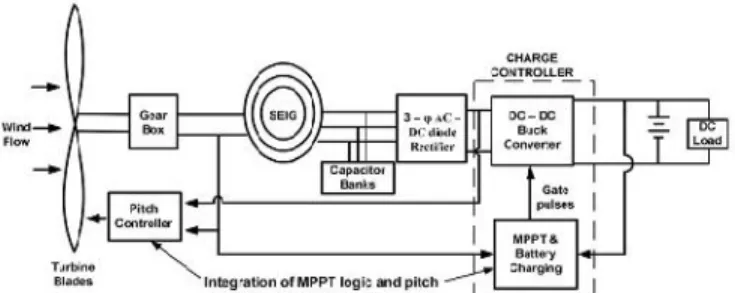
The proposed half breed framework contains a 4-kW WECS and 400 Ah, C/10 lead corrosive battery bank. The framework is intended for a 3-kW remain solitary dc stack. The format of the whole framework alongside the control technique is appeared in Fig. 1. The details of the WT, SEIG, and battery bank are organized in the Appendix. The WECS comprises of a 4.2-kW flat pivot WT, adapt
box with a rigging proportion of 1:8 and a 5.4 hp SEIG as the WTG. Since the heap is a remain solitary dc stack the stator terminals of the SEIG are associated with a capacitor bank for self-excitation. The air conditioner yield is redressed by three-stage uncontrolled diode rectifier. In any case, there is a requirement for a battery reinforcement to take care of the heap demand amid the time of inaccessibility of adequate wind control. This half breed wind-battery framework requires appropriate control rationale for interfacing with the heap. The uncontrolled dc yield of the rectifier is connected to the charge controller circuit of the battery. The charge controller is a dc–dc buck converter which decides the charging and releasing rate of the battery The proposed cross breed framework involves a 4-kW WECS and 400 Ah, C/10 lead corrosive battery bank. The framework is intended for a 3-kW remain solitary dc stack. The format of the whole framework alongside the control procedure is appeared in Fig. 1. The determinations of the WT, SEIG, and battery bank are organized in the Appendix. The WECS comprises of a 4.2-kW level pivot WT, outfit box with an apparatus proportion of 1:8 and a 5.4 hp SEIG as the WTG. Since the heap is a remain solitary dc stack the stator terminals of the SEIG are associated with a capacitor bank for self-excitation. The air conditioner yield is corrected by three-stage uncontrolled diode rectifier. Be that as it may, there is a requirement for a battery reinforcement to take care of the heap demand amid the time of inaccessibility of adequate wind control. This cross breed wind-battery framework requires reasonable control rationale for interfacing with the heap. The uncontrolled dc yield of the rectifier is connected to the charge controller circuit of the battery. The charge controller is a dc–dc buck converter which decides the charging and releasing rate of the battery.
III.CONTROL STRATEGYFORSTAND-ALONEHYBRID WIND-BATTERY SYSTEM
The wind stream is inconsistent in nature. Along these lines, a WECS is coordinated with the heap by methods for an ac–dc–dc converter to stay away from voltage glimmer and symphonious era. The control conspire for a remain solitary half and half wind-battery framework incorporates the charge controller circuit for battery banks and pitch control rationale to guarantee WT operation inside the appraised esteem. The control rationale guarantees powerful control of the WECS against every single conceivable unsettling influence.
A.Charge Controller for the Battery Bank
For the most part, the batteries are charged at C/20, C/10, or C/5 rates relying upon the producer's particular where C determines the Ah rating of battery banks. Along these lines, the battery bank framework considered in the outline can be charged at 20, 40, or 80 A. In any case, in this paper, C/10 rate (i.e., 40 A) for battery charging is picked. Be that as it may, the current required for charging the battery bank relies on upon the battery SoC. A normal battery by and large charges at a consistent current (CC), i.e., C/10 rate mode till battery SoC achieves a specific level (90%–98%). This is alluded to as CC method of battery charging. The CC mode charges the battery as quick as would be prudent. Past this SoC, the battery is charged at a steady voltage (CV) which is meant as CV method of battery charging with a specific end goal to keep up the battery terminal voltage.
B. Control Strategy
The execution of the charge control rationale as appeared in Fig. 2 is done by three settled control circles. The external most control circle works the turbine taking after MPPT rationale with battery SoC restrain. To execute the MPPT rationale, the genuine tip speed proportion (TSR) of turbine is contrasted and the ideal esteem. The mistake is tuned by a PI controller to create the battery current request the length of the battery SoC is underneath the CC mode restrain. Past this point, the SoC control rationale tries to keep up consistent battery charging voltage. This thus lessens the battery current request and consequently keeps the battery bank from cheating. The buck converter inductor current charge is produced in the middle of the road control circle. To outline the controller, it is fundamental to display the reaction of the battery current(Ib)with regard to the inductor current(IL). For controlling the battery current the genuine converter yield current(Id)is contrasted and the reference (Ib +Ia)and the blunder is prepared by a course of a PI and a lead compensator. The PI controller is demonstrated as an upset zero. To keep up the stage edge of the open-circle framework the recurrence of this zero is 50 times lower than the hybrid recurrence. To enhance the stage edge of the battery charging current control circle (i.e., (1) alongside the PI controller) a lead compensator is associated in course with the PI controller as appeared in Fig. 2. The zero and post of the lead compensator are intended to have a positive stage edge and to confine the hybrid recurrence to around 14% of the exchanging recurrence. The yield of the lead compensator decides inductor current reference for the dc–dc converter. Keeping in mind the end goal to avoid over stacking the turbine (and its resulting slowing down) the lead compensator yield is first gone through a movable current limiter. As far as possible is set to zero and as far as possible.
Fig. 1. Layout of hybrid wind–battery system for a stand-alone dc load
IV.MODES OFBATTERYCHARGING A. CC Mode of Battery Charging
In CC mode, the battery charging current request is deflect mined from the MPPT rationale. MPPT is actualized by
com-paring the real and ideal TSR (λopt). The mistake is
tuned by a PI controller to produce the battery charging present according to the wind speed. In this mode, the converter yield voltage ascends with time while the MPPT rationale tries to exchange however much power as could be expected to charge the batteries. The real battery charging current that can be accomplished does not stay steady but rather differs with accessible wind speed subject to a most extreme of C/10 rodent ing of the battery. The battery charging current order has a base utmost of zero. In the event that the wind speed is deficient to supply the heap even with zero battery charging current the inductor current reference is solidified at that specific esteem and the adjust stack current is provided by the battery.
B.CV Mode of Battery Charging
controller must change over from CC mode to CV mode. In CV mode, the battery charging voltage is resolved from the buck converter yield voltage(Vo). The estimation of the converter volt-age when the battery SoC achieves 98% is set as the reference esteem and is contrasted and the genuine converter yield volt-age. The blunder in the voltage is then controlled by a fell course of action of PI controller and lead compensator to create the inductor current reference. It is then contrasted and the air conditioner tual inductor current by a coherent comparator to produce entryway beats correspondingly as portrayed in Section A.
In this mode, the converter yield voltage is kept up at a steady an incentive by the controller activity. Along these lines, in CV mode the battery voltage and SoC rise gradually with time when contrasted with CC mode. The battery accusing current gradually declines of time, since the potential distinction between the buck converter yield and battery terminal bit by bit lessens. Along these lines, in CC mode the buck converter yield current is regu-lated while the yield voltage continues expanding with time. Unexpectedly in CV mode the yield voltage is managed, while the current in the circuit diminishes bit by bit. To concentrate the CC and CV method of battery charging, evaluated estimation of wind speed is connected to the framework. The battery parameters and the converter yield parameters are seen with time.
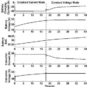
The outcomes are appeared in Fig. 3. As appeared in Fig. 3, the battery is charged both in CC mode and CV mode. The move from CC to CV mode happens when the battery SoC achieves 98%. This is on the grounds that in the present plan, the edge SoC for switch over in the control rationale isset at 98%. As talked about in the before segment, in the CC mode the battery charges at a CC of 40 A which is the C/10 esteem fora 400-Ah battery bank. Amid this mode, both converter yield voltage and battery voltage rise. The battery SoC ascends from an underlying SoC level of 97.95% to 98% inside 17 s. As the battery achieves the limit SoC level, the buck converter voltage is managed by the controller activity at a steady estimation of 53 V while the converter current bit by bit lessens from 40 An at 17 s to 10 An at 40 s. The battery SoC gradually ascends from 98% to 98.03%. The outcomes show that the battery charges at a speedier rate in CC mode when contrasted with CV mode. Accordingly, in CC mode a significant part of the accessible power from essential source is infused into the battery while in CV mode the battery is charged gradually to evade gasification and warming issue.
Fig. 3. Battery charging modes at a constant wind speed of 10 m/s.
B. Pitch Control Mechanism
The WT control yield is corresponding to the 3D square of wind speed. For the most part the cut-off twist speed of a cutting edge WT is substantially higher contrasted with the evaluated wind speed [10]. In the event that the WT is permitted to work over the whole scope of twist speed without usage of any control system, the precise speed of the pole surpasses its appraised esteem which may prompt harm of the sharp edges. In this way, it is especially basic to control the speed and power at twist speeds over the appraised wind speed. This is accomplished by changing the pitch edge of the cutting edge. Such a component is alluded to as the pitch control of WT. The power
coefficient(Cp)versus TSR(λ)characteristics of the WT
WECS. Henceforth, the pitch controller guarantees that with alluring pitch order, the WT parameters and the rectifier yield dc voltage are directed inside their separate most extreme passable cutoff points to guarantee safe operation of the WECS.
Fig. 4. Pitch control scheme for a stand-alone WECS.
V. SPACE VECTOR PULSE WIDTH
MODULATION (SVPWM)
The Space Vector PWM generation module accepts modulation index commands and generates the appropriate gate drive waveforms for each PWM cycle. This section describes the operation and configuration of the SVPWM module.
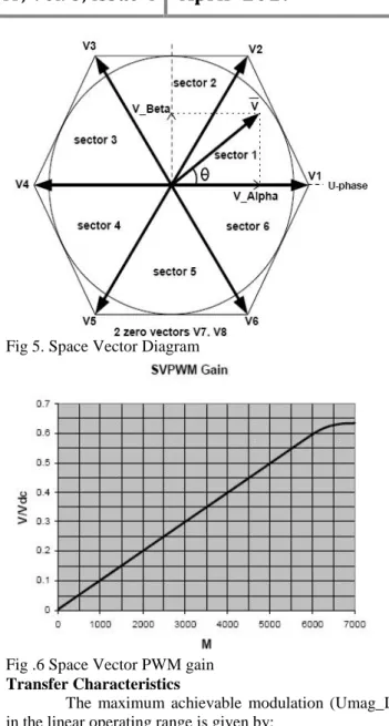
A three-phase 2-level inverter with dc link configuration can have eight possible switching states, which generates output voltage of the inverter. Each inverter switching state generates a voltage Space Vector (V1 to V6 active vectors, V7 and V8 zero voltage vectors) in the Space Vector plane (Figure: space vector diagram). The magnitude of each active vector (V1to V6) is 2/3 Vdc (dc bus voltage).
The Space Vector PWM (SVPWM) module inputs modulation index commands (U_Alpha and U_Beta) which are orthogonal signals (Alpha and Beta) as shown in Figure. The gain characteristic of the SVPWM module is given in Figure 5 . The vertical axis of Figure represents the normalized peak motor phase voltage (V/Vdc) and the horizontal axis represents the normalized modulation index (M).
The inverter fundamental line-to-line Rms output voltage (Vline) can be approximated (linear range) by the following equation:
…………..(1)
Where dc bus voltage (Vdc) is in volts
Fig 5. Space Vector Diagram
Fig .6 Space Vector PWM gain
Transfer Characteristics
The maximum achievable modulation (Umag_L) in the linear operating range is given by:
…………..
(2)
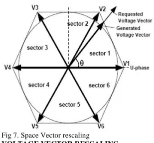
Over modulation occurs when modulation Umag>Umag_L. This corresponds to the condition where the voltage vector in (Figure: voltage vector rescaling)increases beyond the hexagon boundary. Under such circumstance, the Space Vector PWM algorithm will rescale the magnitude of the voltage vector to fit within the Hexagon limit. The magnitude of the voltage vector is restricted within the Hexagon; however, the phase angle
(θ) is always preserved. The transfer gain (Figure: transfer
Fig 7. Space Vector rescaling
VOLTAGE VECTOR RESCALING
This archive is the property of International Rectifier and may not be duplicated or circulated without communicated assent.
PWM OPERATION
After getting the balance list orders (UAlpha and UBeta) the sub-module SVPWM_Tm begins its figurings at the rising edge of the PWM Load flag. The SVPWM_Tm module actualizes a calculation that chooses (in view of area assurance) the dynamic space vectors (V1 to V6) being utilized and computes the suitable time length (w.r.t. one PWM cycle) for every dynamic vector.
The appropriated zero vectors are additionally being chosen. The SVPWM_Tm module devours 11 clock cycles ordinarily and 35 clock cycles (most pessimistic scenario Tr) in over adjustment cases. At the falling edge of nSYNC, another arrangement of Space Vector times and vectors are promptly accessible for real PWM era (PhaseU, PhaseV, PhaseW) by sub module PwmGeneration. It is urgent to trigger PwmLoad no less than 35 clock cycles before the falling edge of nSYNC flag; generally new regulation summons won't be actualized at the soonest PWM cycle. The above Figures voltage vector rescaling delineates the PWM waveforms for a voltage vector situates in area I of the Space Vector plane.
VI. SIMULATION RESULTS
A WECS should be effective to guarantee consistent power stream to the heap. The viability can be accomplished by coordinating the crossover wind-battery framework with appropriate control rationale. This incorporates the charge control rationale and the pitch control rationale. The charge controller directs the charging and releasing rate of the battery bank while the pitch controller controls the WT activity amid high wind
speed conditions or in the event of a power confuse. Both the control technique are coordinated with the cross breed framework and recreated with different twist profiles to approve the adequacy of the framework. The framework is associated with a heap profile shifting in ventures from 0 to 4 kW. The WT parameters like shaft speed, TSR, sharp edge pitch and yield power are broke down with variety in wind speed conditions. The present profile of the converter, stack, and the battery are additionally observed with the wind profile. To guarantee continuous power stream, stack request is given greater need over battery charging. The WT and battery parameters are watched for the accompanying wind profiles.
1) Gradual ascent and fall in wind speed.
2) Step variety in wind speed.
3) Arbitrary variety in wind speed.
A continuous ascent and fall in twist speed as appeared in Fig. 8(a) is connected to the WT. The wind speed bit by bit ascends from 8 to 12 m/s in 15 s and after that tumbles to 8 m/s in the following 15 s. The WT parameters and the present profile of the converter, stack and the battery are seen in Fig. 8(a) and (b). Facilitate the
( (b)
0 5 10 15 20 25 30
5 10 15
W
in
d
pr
of
ile
(m
/s
)
0 5 10 15 20 25 30
-2 0 2 4 6
Pi
tc
h
An
gl
e(
de
g)
0 5 10 15 20 25 30
0 20 40
Sh
af
t
sp
ee
d(
rp
s)
0 5 10 15 20 25 30
0 5 10
TS
R
0 5 10 15 20 25 30
0 5000
Time(s)
Tu
rb
in
e
po
w
er
(W
)
0 5 10 15 20 25 30
0 50 100
In
d
u
ct
o
r
cu
rr
en
t(
A
)
0 5 10 15 20 25 30
0 5000
L
o
ad
p
o
w
er
(W
)
0 5 10 15 20 25 30
50 50.5 51
B
at
te
ry
vo
lt
ag
e(
V
)
0 5 10 15 20 25 30
-50 0 50
B
at
te
ry
cu
rr
en
t(
A
)
0 5 10 15 20 25 30
97.79 97.8 97.81
Time(s)
B
at
te
ry
so
Fig..8 (a)WT and (b)battery parameters under the influence of gradual variation of wind speed efficiency of the complete control scheme is validated with a step variation in wind profile and an arbitrary varying wind speed. The variation of the wind profile in step from 8 to 12 m/s is shown in Fig. 9(a) while the arbitrary variation in wind speed from 6 to 14 m/s is highlighted in Fig 10(a). The response of WT parameter and the current profiles with respect to step variations and arbitrary variations are shown in Figs. 9 and 10, respectively. The results also demonstrate the change in battery SoC for all possible wind profiles.
(a)
(b)
Fig. 9. (a)WT and (b)battery parameters under the influence of step variation of wind speed
(a)
(b)
Fig.10. (a)WT and (b)battery parameters under the influence of arbitrary variation of wind speed
0 5 10 15 20 25 30
5 10 15 W in d s p e e d (m /s )
0 5 10 15 20 25 30
-2 0 2 4 6 P it c h A n g le (m /s )
0 5 10 15 20 25 30
0 20 40 S h a ft s p e e d (r p s )
0 5 10 15 20 25 30
0 5 10 T S R
0 5 10 15 20 25 30
0 5000 Time(s) T u rb in e p o w e r( W )
0 5 10 15 20 25 30
0 50 100 In d u c to r c u rr e n t( A )
0 5 10 15 20 25 30
0 5000 L o a d p o w e r( W )
0 5 10 15 20 25 30
50 51 52 L o a d v o lt a g e (V )
0 5 10 15 20 25 30
-50 0 50 B a tt e ry c u rr e n t( A )
0 5 10 15 20 25 30
97.79 97.8 97.81 Time(s) B a tt e ry s o c
0 5 10 15 20 25 30
5 10 15 W in d p ro fi le (m /s )
0 5 10 15 20 25 30
-20 2 4 6 8 P it c h A n g le (m /s )
0 5 10 15 20 25 30
0 20 40 S h a ft s p e e d (r p s )
0 5 10 15 20 25 30
0 5 10 T S R
0 5 10 15 20 25 30
0 5000 Time(s) T u rb in e p o w e r( W )
0 5 10 15 20 25 30 0 50 100 In d u c to r c u rr e n t( A )
0 5 10 15 20 25 30 0 5000 L o a d p o w e r( W )
0 5 10 15 20 25 30 50 51 52 L o a d v o lt a g e (V )
0 5 10 15 20 25 30 -50 0 50 B a tt e ry c u rr e n t( A )
From Figs 8–10, it is watched, that when the wind speed is beneath the appraised esteem (10 m/s) the MPPT conspire manages the TSR of WT at its ideal esteem independent of the variety in wind profile. Along these lines most extreme power is extricated from WECS at all twist rates to meet the heap necessity and charge the battery bank. However, the wind power is not generally adequate to take care of the heap demand and charge the battery in CC mode. In
such circumstances the framework initially meets the heap necessity and charges the battery bank at a lessened rate. Also, when th wind power is not satisfactory according to the heap request, the battery releases to meet the deficiency. The battery SoC increments amid charging yet diminishes while releasing. Nonetheless, the charge controller guarantees that the battery current amid charging or releasing never surpasses 40 A. The pitch point of WT is kept up at zero deg at twist speed underneath 10 m/s. Be that as it may, the pitch controller is actuated as the wind speeds surpasses its evaluated constrain. The expansion in the pitch edge constrains the power and speed yield inside the sheltered furthest reaches of WT operation. The reaction of WT and streams for every single conceivable variety in twist profile with space vector adjustment method undoubtedly demonstrate the viability of the proposed control rationale for the half breed wind–battery framework.
V.CONCLUSION
The power accessible from a WECS is extremely problematic in nature. Along these lines, a WECS can't guarantee continuous power stream to the heap. Keeping in mind the end goal to meet the heap prerequisite at all cases, appropriate capacity gadget is required. Thusly, in this venture, a cross breed wind-battery framework is provided the coveted load control. To relieve the irregular attributes of wind stream the WECS is interfaced with the heap by appropriate controllers. The control rationale actualized in the half and half set up incorporates the charge control of battery bank utilizing MPPT and pitch control of the WT for guaranteeing electrical and mechanical security. The charge controller tracks the most extreme power accessible to charge the battery bank in a controlled way. Advance it likewise ensures that the batteries release current is additionally inside the C/10 restrict. The current customized control strategy intrinsically shields the buck converter from over current circumstance. Be that as it may, now and again because of MPPT control the source power might be more when contrasted with the battery and load request. Amid the power confound conditions, the pitch activity can manage the pitch point to lessen the WT yield control as per the aggregate request. Other than controlling the WT qualities, the pitch control rationale ensures that the rectifier voltage
does not prompt an overvoltage circumstance. The half breed wind-battery framework alongside its control rationale is produced in MATLAB/SIMULINK and is tried with different wind profiles. The result of the recreation comes about approves the enhanced execution of the framework.
REFERENCES
[1]. Aradhya Sambhu Satpathy, N. K. Kishore,
Debaprasad Kastha, and N.C.Sahoo, “Control
Scheme for a Stand-Alone Wind Energy Conversion
System,” IEEE Trans. Energy Convers., vol. 29, no.
2, pp. 418–425, Jun. 2014.
[2]. A. D. Sahin, “Progress and recent trends in wind energy,” Progress in Energy Combustion Sci., vol. 30,
no. 5, pp. 501–543, 2004.
[3] R. D. Richardson and G. M. Mcnerney, “Wind energy
systems,” Proc.IEEE, vol. 81, no. 3, pp. 378–389,
Mar. 1993.
[4] R. Saidur, M. R. Islam, N. A. Rahim, and K. H.
Solangi, “A review on global wind energy policy,”Renewable Sustainable Energy Rev., vol.
14,no. 7, pp. 1744–1762, Sep. 2010.
[5] M. T. Ameli, S. Moslehpur, and A. Mirzale,
“Feasibility study for replac-ing asynchronous
genrators with synchronous generators in wind farm
power stations,” inProc. IAJC –IJME, Int. Conf. Eng.
Technol.,Music City Sheraton, Nashville, TN, US, ENT paper 129Nov. 17–19, 2008.
[6] G. K. Singh, “Self excited generator research—A
survey,”Electric Power Syst. Res., vol. 69, no. 2/3,
pp. 107–114, 2004.
[7] R. C. Bansal, “Three-phase self-excited induction
generators: An overview,”IEEE Trans. Energy
Convers., vol. 20, no. 2, pp. 292–299, Jun. 2005.
[8] S. C. Tripathy, M. Kalantar, and N. D. Rao, “Wind
turbine driven self excited induction
generator,”Energy Convers. Manag., vol. 34, no.
8,pp. 641–648, 1993.
[9] A. Chakraborty, “Advancements in power electronics
and drives in inter-face with growing renewable
energy resources,”Renewable Sustainable Energy
Rev., vol. 15, no. 4, pp. 1816–1827, May 2011. [10] F. D. Gonz´ alez, A. Sumper, O. G. Bellmunt, and R.
V. Robles, “A review of energy storage technologies
for wind power applications,”Renewable Sustainable
Energy Rev., vol. 16, no. 4, pp. 2154–2171, May 2012.
[11] N. S. Hasan, M. Y. Hassan, M. S. Majid, and H. A.
Rahman, “Review of storage schemes for wind energy systems,”Renewable Sustainable Energy Rev.,
vol. 21, pp. 237–247, May 2013.
[12] A. M. D. Broe, S. Drouilhet, and V. Gevorgian, “A
charging applications,”IEEE Trans. Energy Convers.,
vol. 14, no. 4, pp. 1630–1635, Dec. 1999.
[13] R. Kot, M. Rolak, and M. Malinowski, “Comparison
of maximum peak power tracking algorithms for a
small wind turbine,”Math. Comput. Simul., vol. 91,
pp. 29–40, 2013.
[14] M. Narayana, G. A. Putrus, M. Jovanovic, P. S.
Leung, and S. McDonald, “Generic maximum power
point tracking controller for small-scale wind
turbines,”Renewable Energy, vol. 44, pp. 72–79,
Aug. 2012.
[15] K. Y. Lo, Y. M. Chen, and Y. R. Chang, “MPPT
battery charger for stand-alone wind power
system,”IEEE Trans. Power Electron., vol. 26, no. 6,
pp. 1631–1638, Jun. 2011.
Authors:
K Sri Ram Murthy currently working
as aAsst. Professor, in Department of EEE, Pydah Engineering College, Kakinada India.He completed his M.TECH in the area of power electronics and drives in JNTUK.His interested areas are control systems and power electronics.
.
K D VS Mithilesh pursuing M.TECH