The Efficient Adaptive Pre-Encoded Multipliers Based on (NR4SD) Encoding for
Digital Signal Processing Applications
Guggilla.Satya Sudha , Chintha.Sri Pothu Raju M.Tech.(Embedded Systems)
VSM college of engineering
[email protected], [email protected]
Abstract
Multimedia and Digital Signal Processing (DSP) applications (e.g., Fast Fourier Transform (FFT), audio/video CoDecs) complete countless with coefficients that don't change amid the execution of the application. Since the multiplier is an essential part to implement computationally concentrated applications, its engineering truly influences their execution. A committed encoding circuit is required and the fractional items age is more mind boggling. A strategy practically identical is proposed for sketching out compelling MB multipliers for social occasions of pre-chosen coefficients with a comparable imperative. Encode the coefficients disengaged in perspective of the MB encoding and store the MB encoded coefficients (i.e., 3 bits for each digit) into a ROM. New layouts of pre-encoded multipliers are researched by detached encoding the standard coefficients and securing them in system memory. We propose encoding these coefficients in the Non-Redundant radix-4 Signed-Digit (NR4SD) outline. The proposed pre-encoded NR4SD multiplier designs are a more area and power compelling stood out from the conventional and pre-encoded MB diagrams
Key words: modified booth scheme, Non excess radix-4 Signed digit encoding (NR4SD), partial products,, encoding.
I. Introduction
Multipliers assume a critical part in the present digital signal processing and different applications. With progresses in innovation, numerous analysts have attempted and are endeavoring to plan multipliers which offer both of the accompanying outline targets – fast, low power utilization, normality
of design and henceforth less region or even blend of them in one multiplier in this manner making them reasonable for different rapid, low power and smaller VLSI usage.
The basic common technique is "add and shift" algorithm. In parallel multipliers number of incomplete items to be add is the fundamental parameter that decides the execution of the multiplier. To lessen the quantity of incomplete items to be add, Modified Booth algorithm is a standout amongst the most well-known algorithms. To accomplish speed upgrades Wallace Tree algorithm can be utilized to lessen the quantity of successive including stages. Advance by joining both Modified Booth algorithm and Wallace Tree procedure we can see favorable position of the two algorithms in a single multiplier. Anyway with expanding parallelism, the measure of shiftment between the incomplete items and middle of the road entireties to be add will build which may bring about decreased speed, increment in silicon region because of abnormality of structure and furthermore expanded power utilization because of increment in interconnect coming about because of complex directing. Then again "serial-parallel" multipliers trade off speed to accomplish better execution for territory and power utilization. The choice of a parallel or serial multiplier really relies upon the idea of use. In this address we present the increase algorithms and engineering and look at them as far as speed, region, power and mix of these measurements. Shift and Add Multiplier:
is addd and gathered. At each clock cycle the multiplier is shiftd one piece to one side and its esteem is tried. On the off chance that it is a 0, at that point just a shift task is performed. In the event that the esteem is a 1, at that point the multiplicand is added to the collector and is shiftd by one piece to one side. After all the multiplier bits have been tried the item is in the aggregator. The gatherer is 2N (M+N) in measure and at first the N, LSBs contains the Multiplier. The deferral is N cycles most extreme. This circuit has a few points of interest in offbeat circuits.
Array Multipliers:
Array multiplier is outstanding because of its customary structure. Multiplier circuit depends on add and shift algorithm. Every incomplete item is produced by the common of the multiplicand with one multiplier bit. The halfway item are shiftd by their bit requests and afterward addd. The expansion can be performed with typical convey proliferate viper. N-1 adders are required where N is the multiplier length.
Booth Multipliers:
It is an intense algorithm for marked number augmentation, which treats both positive and negative numbers consistently. For the standard add shift task, every multiplier bit creates one different of the multiplicand to be added to the fractional item. In the event that the multiplier is expansive, at that point countless must be addd. For this situation the postponement of multiplier is resolved predominantly by the quantity of increments to be performed. On the off chance that there is an approach to diminish the quantity of the augmentations, the execution will show signs of improvement.
II. Related work
Cui, x et al [4], depicted another RB altered fractional item generator (RBMPPG). The customary RB multiplier requires an extra RB halfway item (RBPP) push, in light of the fact that a mistake rectifying word (ECW) is produced by both the radix-4 Modified Booth encoding (MBE) and the RB encoding. It evacuates the additional ECW and thus, it spares one RBPP gathering stage. Jaiswal,K.B,et al [5],suggested an Achieving fast coordinated circuits
(PACS). PACS starts by producing a few potential arrangements in view of both restrictive and expected likelihood, where upon the exactness of the arrangements is confirmed utilizing PC recreation and the arrangement with the most noteworthy precision is chosen. Notwithstanding being very precise, the proposed PACS approach is zone powerful. The plan has been checked effectively on DE2115 and after that orchestrated to ASIC usage. The FPGA based test result demonstrates that it has the assets of 1788 ALUTs. The combined outcome involves a territory of 58.28 mm2 with 4.13 ns add up to delay (i.e. 242.13MHz most extreme recurrence).
III. Diverse Types of Multipliers
A. Iterative Techniques
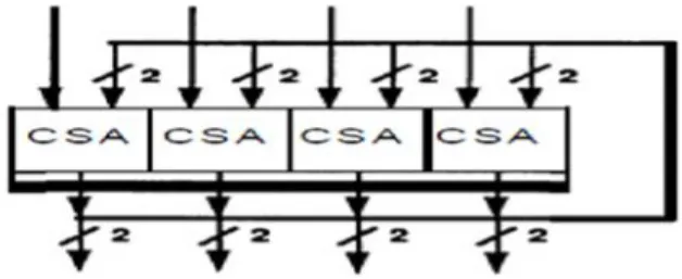
To decrease zone, a couple of makers use midway displays and stress using a clock. At the purpose of constrainment, an irrelevant iterative structure would have one section of CSA's and a bolt. Clearly, this structure requires insignificant measure of hardware, and has the most important use since each CSA is used each cycle as showed up in Fig.2. A basic observation is that iterative structures are fast if the bolt delays are close to nothing, and the clock is composed to the combinational deferment of the CSA's. If both of these conditions are met, iterative structures approach an unclear throughput and idleness from full groups. The primary differentiation in dormancy is a direct result of the bolt and clock overhead. In spite of the way that they require snappy tickers, two or three associations use iterative structures in their new world class floating point processors.
Fig. 1 Minimal Iterative Structures.
While endeavoring to grow execution of the immaterial iterative structure additional lines of CSA's could be added to make a more noteworthy show. For example, the development of one section
of CM's to the insignificant structure would yield a midway group with two lines of CM's. This structure gives two purposes of enthusiasm over the single line of CSA cells:
• It decreases the required clock repeat, and
• It requires simply a large portion of a similar number of bolt delays.
It is basic to observe that regardless of the way that the amount of CSA's has been increased, the inactivity was reduced just by separating the amount of snare delays. The amount of CSA concedes proceeds as previously. In this way, tolerating the snare delays are little in regard to the CSA delays, extending the significance of the deficient display by including additional segments of CSA's in an immediate structure yields only a slight augmentation in execution.
B. Nuts and bolts of Multipliers
Increment is a numerical movement that in any event troublesome is an abbreviated strategy of adding an entire number to itself a foreordained number of times. A number (multiplicand) is added to itself different conditions as demonstrated by another number (multiplier) to shape a result (thing). In elementary school, understudies make sense of how to increment by setting the multiplicand over the multiplier. The multiplicand is then copied by each digit of the multiplier beginning with the farthest right, Least Significant Digit (LSD). Center results (fragmentary things) are set one on the other, adjust by one digit to alter digits of a comparable weight. The last thing is managed by summation of all the deficient things. Yet by far most consider expansion just in base 10, this method applies likewise to any base, including parallel. Figs.3 and 4 exhibits the data stream for the principal growth strategy just depicted. Every dull spot addresses a single.
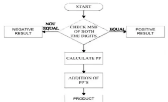
Fig. 3 Signed Multiplication Algorithms.
Here, we expect that MSB speak to the indication of the digit. The activity of augmentation is somewhat basic in digital gadgets. It has its source from the established calculation for the result of two parallel numbers. This calculation utilizes expansion and move left activities to compute the result of two numbers. In light of the above method, we can find a calculation.
C. Binary Multiplication
In the paired number framework the digits, called bits, are restricted to the set [0, 1]. The consequence of duplicating any twofold number by a solitary parallel piece is either 0, or the first number. This makes shaping the halfway partialproducts basic and proficient. Summing these partialproducts is the tedious errand for twofold multipliers. One consistent approach is to shape the fractional items each one in turn and entirety them as they are produced. Regularly actualized by programming on processors that don't have an equipment multiplier, this technique works fine, yet is moderate in light of the fact that no less than one machine cycle is required to aggregate each extra incomplete item. For applications where this approach does not give enough execution, multipliers can be actualized specifically in equipment. The two fundamental classifications of twofold augmentation incorporate signed and unsigned numbers. Digit common is a progression of bit movements and arrangement of bit increments, where the two numbers, the multiplicand and the multiplier are joined into the outcome. Considering the bit portrayal of the multiplicand x = xn1… ..x1 x0 and the multiplier y = yn-1… ..y1y0 with a specific end goal to shape the item up to n
moved duplicates of the multiplicand are to be addd for unsigned increase. The whole procedure comprises of three stages, fractional item age, halfway item diminishment and last expansion. D. Multiplication Process
Let 11012 (−310) and 01012 (510), when processing the item by hand, which can be portrayed by fig.5.
Fig. 4 Multiplication computations by hand.
The strong italic digits are the sign expansion bits of the fractional items. The main operand is known as the multiplicand and the second the multiplier. The halfway items are called fractional items and the last outcome is known as the item. Notwithstanding, the increase procedure, when this technique is specifically mapped to equipment, is appeared in fig.6. As can been found in the figures, the common activity in equipment comprises of PP age, PP lessening and last expansion steps. The two lines previously the item are called entirety and convey bits. The task of this technique is to take one of the multiplier bits at any given moment from ideal to left, increasing the multiplicand by the single piece of the multiplier and moving the middle of the road item one position to one side of the prior moderate items.
Fig. 5 Multiplication 0peration in equipment.
In order to achieve high-speed multiplication, multiplication algorithms using parallel counters, such as the modified Booth algorithm has been proposed, and some multipliers based on the algorithms have been implemented for practical use. This type of multiplier operates much faster than an array multiplier for longer operands because its computation time is proportional to the logarithm of the word length of operands.
Corner augmentation is a technique that takes into account littler, quicker common circuits, by recoding the numbers that are increased. It is conceivable to decrease the quantity of halfway items significantly, by utilizing the technique of radix-4 Booth recoding. The essential thought is that, rather than moving and including for each segment of the multiplier term and increasing by 1 or 0, we just take each second section, and duplicate by ±1, ±2, or 0, to acquire similar outcomes. The benefit of this strategy is the dividing of the quantity of incomplete items. To Booth recode the multiplier term, we think about the bits in squares of three, with the end goal that each piece covers the past square by one piece. Gathering begins from the LSB, and the principal piece just uses two bits of the multiplier. Figure 3 demonstrates the gathering of bits from the multiplier term for use in adjusted stall encoding.
Fig.6 Grouping of bits from the multiplier term Each piece is decoded to create the right halfway item. The encoding of the multiplier Y, utilizing the adjusted corner calculation, produces the accompanying five signed digits, - 2, - 1, 0, +1, +2. Each encoded digit in the multiplier plays out a specific activity on the multiplicand, X, as showed in Table 1
For the fractional item age, we receive Radix-4 Modified Booth calculation to decrease the quantity of incomplete items for about one half. For increase of 2's supplement numbers, the good for nothing encoding utilizing this calculation examines a triplet of bits. At the point when the multiplier B is separated into gatherings of two bits, the calculation is connected to this gathering of isolated bits.
NON-REDUNDANT RADIX-4 SIGNED DIGIT ALGORITHM:
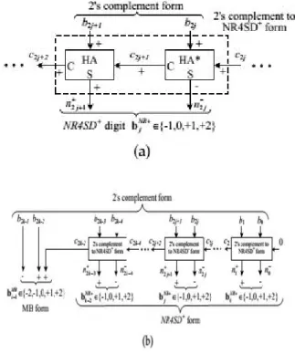
Fig. 7. 1. Block Diagram of the NR4SD Encoding Scheme at the (a) Digit and (b) Word Level.
NR4SD--Algorithm
Step 1: Consider the initial values j = 0 and C0=0.
Step 2: Calculate the carry C2j+1and the sum of a
Half Adder (HA) with inputs and (Fig. 1a).
Step 3: Calculate the positively signed carry and the negatively signed sum of a Half Adder* (HA*) with inputs and (Fig. 1a). The outputs and n2j+1of the HA* relate to its inputs as follows:
The following Boolean equations summarize the HA* operation:
Step 4: Calculate the value of the bNRj digit.
Equation (5) results from the fact that is negatively signed and is positively signed.
Step 5: j := j + 1.
Step 6: If (j < k-1), go to Step 2. If (j = k-1), encode the most significant digit based on the MB algorithm and considering the three consecutive bits to be
(Fig. 1b). If (j = k), stop.
The base and most extreme points of confinement of the dynamic range in the NR4SD+form are 2n 12n 42n 6 1 < 2n 1and 2n 1+2n 3+2n 5+ +2 > 2n 11. As saw in the NR4SD encoding technique,the NR4SD+form has bigger dynamic range than the 2's supplement frame.
Considering the 8-bit 2's supplement number N, Table 4 uncovered the farthest point esteems 28= 28, 281 =127, and two normal estimations of N, and presents the MB, NR4SD and NR4SD+ digits that outcome while applying the comparing encoding techniques to each estimation of N we considered. We addd a bar over the adversely signed digits keeping in mind the end goal to recognize them from the decidedly signed ones.
Fig.7. 3. System Architecture of the Conventional MB Multiplier.
Conventional MB Multiplier
Fig. 7.3 presents the engineering of the framework which involves the regular MB multiplier and the ROM with coefficients in 2's supplement shape. Give us a chance to consider the increase A.B. The coefficient B = (b n-1… … b0)s comprises of n=2k bits and is headed to the MB encoding hinders from a ROM where it is put away in 2's supplement shape. It
is encoded by the MB calculation (Section 2) and duplicated by A = (a … . a0) , which is in 2's supplement portrayal. We take note of that the ROM information transport width measures up to the width of coefficient B (n bits) and that it yields one coefficient on each clock cycle.The k partial items are produced as takes after:
The age of the ith bit pj;i of the partial item P Pj is represented at entryway level in Fig. 4a For the calculation of the slightest and most critical bits of P Pj , we consider a 1=0 and a = a 1, separately. Subsequent to molding the incomplete items, they are addd, legitimately weighted, through a Carry Save Adder (CSA) tree alongside the adjustment term (COR):
Where cin;j = (onej _twoj )^sj (Table 1). The CS outputof the tree is leaded to a quick Carry Look Ahead (CLA) adder to shape the last outcome P = A B (Fig. 3).
Subsequently, the PPG of Fig. 4a is supplanted by the one of Fig. 4b. Contrasted with (4), (12) prompts a more mind boggling plan. Be that as it may, due to the pre-encoding technique, there is no region/postpone overhead at the circuit.
The fractional items, appropriately weighted, and the rectification term (COR) of (11) are sustained into a CSA tree. The information convey cin;j of (11) is figured as cin;j = sj in light of (12) and Table 1. The CS yield of the tree is at last converged by a quick CLA adder.
In any case, the ROM width is expanded. Every digit demands three encoding bits (i.e., s, two and one (Table 1)) to be put away in the ROM. Since the n-bit coefficient B needs three bits for each digit when encoded in MBform, the ROM width necessity is 3n/2 bits for each coefficient. Subsequently, the width and the general size of the ROM are expanded by half contrasted with the ROM of the regular plan (Fig. 3).
Pre-Encoded NR4SD Multipliers Design
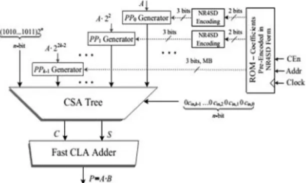
Fig 7.4. Framework Architecture of the NR4SD Multipliers.
The framework engineering for the pre-encoded NR4SD multipliers is exhibited in Fig. 3.4. Two bits are presently put away in ROM: n2j+1, n+2j(Table 2) for the NR4SDor n+2j+1, n2j(Table 3) for the NR4SD+form. Along these lines, we lessen the memory prerequisite to +1 bits for every coefficient while the relating memory required for the pre-encoded MB plot is 3n/2 bits for every coefficient. In this way, the measure of put away bits is equivalent to that of the ordinary MB configuration, with the exception of the most critical digit that needs an
additional piece as it is MB encoded. Contrasted with the pre-encoded MB multiplier, where the MB encoding pieces are overlooked, the pre-encoded NR4SD multipliers require additional equipment to create the signals of (6) and (8) for the NR4SD and NR4SD+ frame, separately. The NR4SD encoding squares of Fig. 6 actualize the hardware of Fig. 3.5 Every partial result of the pre-encoded NR4SD and NR4SD+ multipliers is executed in light of Fig. 4c and 4d, individually, with the exception of the P Pk 1 that compares to the most critical digit. As this digit is in MB frame, we utilize the PPG of Fig. 4b applying the change specified in Section 4.2 for the s j bit. The partial items, legitimately weighted, and the amendment term (COR) of (11) are encouraged into a CSA tree. The info convey cin;j of (11) is ascertained as cin;j = twoj_ onej and cin;j = onej for the NR4SDand NR4SD+pre-encoded multipliers, individually ,in view of Tables 2 and 3. The convey spare yield of the CSA tree is at long last summed utilizing a quick CLA adder.
Fig. 7.5. Extra Circuit Needed in the NR4SD Multipliers to Complete the (a) NR4SD-- and (b)
NR4SD+Encoding.
V. Results
Simulation Results:
Form the synthesis report we are getting that area required for 16 bit modified booth algorithm is 297 slices .whereas NRS4D–required is 129 slices. And
for NRS4D+ required 134 slices. From this we are
Fig3.5.8: simulation result for modified booth encoding for 16 bits.
Fig3.5.9: simulation result for NR4SD-for 16 bit
Fig3.5.10: simulation result for NRS4D+for 16 bits.
VII. Conclusion
In this paper, new outlines of pre-encoded multipliers are investigated by disconnected encoding the standard coefficients and putting away them in framework memory. We propose encoding these coefficients in the Non-Redundant radix-4 Signed-Digit (NR4SD) shape. The proposed pre-encoded NR4SD multiplier plans are more territory and power effective contrasted with the traditional and pre-encoded MB outlines. Broad trial examination
confirms the increases of the proposed pre-encoded NR4SD multipliers as far as zone many-sided quality and power utilization contrasted with the regular MB multiplier.
References
[1] G. W. Reitwiesner, “Binary arithmetic,” Advances in Computers,vol. 1, pp. 231–308, 1960. [2] K. K. Parhi, VLSI Digital Signal Processing Systems: Design andImplementation. John Wiley & Sons, 2007.
[3] K. Yong-Eun, C. Kyung-Ju, J.-G. Chung, and X. Huang, “Csdbased programmable multiplier design for predetermined coefficient groups,” IEICE Trans. Fundam. Electron. Commun.Comput. Sci., vol. 93, no. 1, pp. 324–326, 2010.
[4] O. Macsorley, “High-speed arithmetic in binary computers,” Proc. IRE, vol. 49, no. 1, pp. 67–91, Jan. 1961.
[5] W.-C. Yeh and C.-W. Jen, “High-speed booth encoded parallel multiplier design,” IEEE Trans. Comput., vol. 49, no. 7, pp. 692–701, Jul. 2000. [6] Z. Huang, “High-level optimization techniques for low-power multiplier design,” Ph.D. dissertation, Department of Computer Science, University of California, Los Angeles, CA, 2003.
[7] Z. Huang and M. Ercegovac, “High-performance low-power left-to-right array multiplier design,” IEEE Trans. Comput., vol. 54, no. 3, pp. 272–283, Mar. 2005.
[8] Y.-E. Kim, K.-J. Cho, and J.-G. Chung, “Low power small area modified booth multiplier design for predetermined coefficients,” IEICE Trans. Fundam. Electron. Commun. Comput. Sci., vol. E90-A, no. 3, pp. 694–697, Mar. 2007.
[9] C. Wang, W.-S. Gan, C. C. Jong, and J. Luo, “A low-cost 256-point fft processor for portable speech and audio applications,” in Int. Symp. on Integrated Circuits (ISIC 2007), Sep.2007, pp. 81–84.