CANopen Communication
Protocol
SM 137 - SM 140 motors
02
Publication information
CNI ENGINEERING S.r.l.
No part of this manual may be reproduced or transmitted in any form or by any means, electronic or mechanic, including photocopying, without the express written permission of CNI Engineering.
Update List
Revision Added Deleted Changed
00 Unreleased
01 Sect. 9.1
Documentation office
Document Code:
Document revision:
Document edition:
Via Carpanelli, 24
40011 Anzola dell'Emilia (Bo) Italy
Tel. +39 051 6508911
Fax +39 051 6508912
[email protected]
www.cnicnc.com
Via dell’Artigianato, 1
48011 Alfonsine (Ra) Italy
Tel. +39 0544 84277
Fax +39 0544 80635
P.I. e C.F. 02248390391
Registered offices
H5834D0009ING
02
05/15/2007
INDEX
1
Introduction to the CANopen communication protocol ...1
1.1
"CiA (Can in Automation) specifications ... 1
1.2
Object Dictionary ... 1
1.3
DS 301 Protocols ... 1
1.4
DS301 States ... 2
1.5
DSP 402 States ... 3
1.6
Operating modes ... 5
1.7
Serial communication protocol ... 5
2
Object Dictionary...7
2.1
Definition of an object ... 7
2.1.1
Object description table ... 7
2.1.2
Object description table ... 8
3
Object Dictionary DS 301...11
3.1
Object 1000
h: Device Type ... 11
3.2
Object 1001
h: Error Register ... 11
3.3
Object 1002
h:Manufacturer Status Register ... 12
3.4
Object 1008
h: Manufacturer Device Name ... 13
3.5
Object 1009
h: Manufacturer Hardware Version ... 13
3.6
Object 100A
h: Manufacturer Software Version ... 14
3.7
Object 100C
h: Guard Time ... 15
3.8
Object 100D
h: Life Time Factor ... 16
3.9
Object 1010
h: Store Parameters ... 17
3.10
Object 1011
h: Restore Parameters ... 18
3.11
Object 1014
h: COB-ID Emergency Message ... 19
3.12
Object 1400
h: 1
stReceive PDO Parameter ... 20
3.13
Object 1401
h: 2
ndReceive PDO Parameter ... 22
3.14
Object 1600
h: 1
stReceive PDO Mapping Parameter ... 24
3.15
Object 1601
h: 2
ndReceive PDO Mapping Parameter ... 27
3.16
Object 1800
h: 1st Transmit PDO Parameter ... 30
3.17
Object 1801
h: 2
ndTransmit PDO Parameter ... 32
3.18
Object 1A00
h: 1
stTransmit PDO Mapping Parameter ... 34
3.19
Object 1A01
h: 2nd Transmit PDO Mapping Parameter ... 37
4
Object Dictionary: objects defined by the manufacturer...41
4.1
Object 2000
h: Proportional Gain of Current Loop ... 41
4.3
Object 2004
h: Maximum Value of Current Loop Output ... 42
4.4
Object 2005
h: Proportional Gain of Speed Loop ... 42
4.5
Object 2006
h: Integral Gain of Speed Loop ... 43
4.6
Object 2007
h: Percentage Feedforward for Speed Loop ... 43
4.7
Object 2009
h: Maximum Value of Speed Loop Output ... 44
4.8
Object 200A
h: Proportional Gain of Position Loop ... 44
4.9
Object 200B
h: Integral Gain of Position Loop ... 45
4.10
Object 200C
h: Percentage Feedforward for Position Loop ... 45
4.11
Object 200E
h: Maximum Value of Position Loop Output ... 46
4.12
Object 200F
h: Maximum Speed Following Error ... 46
4.13
Object 2010
h: Maximum Duration of Speed Following Error ... 47
4.14
Object 2011
h: Maximum Torque ... 47
4.15
Object 2012
h: Timeout for Maximum Torque ... 48
4.16
Object 2013
h: Bit_A ... 48
4.17
Object 2014
h: Electric Angle On Zero Index ... 49
4.18
Object 2015
h: First Component of Speed Loop Feedforward ... 49
4.19
Object 2016
h: Second Component of Speed Loop Feedforward ... 50
4.20
Object 2017
h: Third Component of Speed Loop Feedforward ... 50
4.21
Object 2018
h: Fourth Component of Speed Loop Feedforward ... 51
4.22
Object 3000
h: Special Commands ... 51
4.23
Object 3010
h: Sampling Variables ... 54
4.24
Object 5f00
h: Reserved ... 55
4.25
Table Bit_A ... 56
5
Objects Dictionary: DSP402 ... 57
5.1
Object 6040
h: Controlword ... 57
5.2
Object 6041
h: Statusword ... 58
5.2.1
Controlword and Statusword in 'Profile Position Mode' ... 60
5.2.2
Controlword and Statusword in 'Profile Velocity Mode' ... 66
5.2.3
Controlword and Statusword in 'Homing Mode' ... 67
5.3
Object 6060
h: Modes of operation ... 69
5.4
Object 6061
h: Modes of operation display ... 71
5.5
Object 6064
h: Position Actual Value ... 72
5.6
Object 6065
h: Following Error Window ... 72
5.7
Object 6066
h: Following Error Timeout ... 73
5.8
Object 6067
h: Position Window ... 73
5.9
Object 6068
h: Position Window Time ... 74
5.10
Object 606B
h: Velocity Demand Value ... 75
5.11
Object 606C
h: Velocity Actual Value ... 75
5.12
Object 607A
h: Target Position ... 76
5.13
Object 607C
h: Homing Offset ... 76
5.14
Object 607D
h: Software Position Limit ... 77
5.15
Object 6081
h: Profile Velocity ... 78
5.16
Object 6083
h: Profile Acceleration ... 78
5.17
Object 6085
h: Quick Stop Deceleration ... 79
5.18
Object 6098
h: Homing Method ... 79
5.19
Object 6099
h: Homing Speed Value ... 80
6
Objects that are not implemented...81
6.1
Object 6007
h: Abort Connection Option Code ... 81
6.2
Object 605A
h: Quick Stop Option Code ... 82
6.3
Object 605C
h: Disable Operation Option Code ... 83
6.4
Object 605B
h: Shutdown Option Code ... 84
6.5
Object 605D
h: Halt Option Code ... 85
6.6
Object 605E
h: Fault Reaction Option Code ... 86
7
Emergency Messages ...87
8
SDO Interrupt Codes ...89
9
Dip-switch configuration ...91
9.1
Baudrate ... 91
9.2
Restoring Default parameters ... 91
9.3
Node number ... 92
1
Introduction to the CANopen communication protocol
This section summarises the basic concepts behind the CANopen communication protocol. For a more thorough discussion, please refer to the following documents:• "CANopen Application Layer and Communication Profile - CiA Draft Standard 301 - Version 4.02".
1.1
"CiA (Can in Automation) specificationsIn the attempt to standardise the various devices that can be used on a CAN bus, the CiA has issued a series of specifications with which a device must comply in order to be considered "CANopen". These specifications define the objects that must/may be present in the Object Dictionary and the various communication protocols implemented. The two reference
specifications used in this manual are "DS 301" which refers to a generic device, and "DSP 402" relating to servomotors.
In the following we will first look at the contents of the DS 301 specifications, as these are general and relate to all CANopen devices. Subsequently we will also discuss the specification DSP 402 and thus take a more detailed look at how a CANopen servomotor operates.
1.2
Object Dictionary
Each CANopen device has an “object dictionary” containing all the device parameters. By reading and writing these parameters it is possible to send commands to the CANopen device and monitor its state. Each object is defined by an index and a subindex which identify that object. For
example: the real position of the motor is identified by the object with index 0x6064 and subindex 0x00.
1.3
DS 301 Protocols
The types of protocol defined in the DS 301 specifications are as follows:
• SDO protocol. This allows reading and writing of the device objects, whatever their length and type. It involves the exchange of index, subindex and length, as well as the value of the object it accesses. The protocol can be divided into write SDO (download) and read SDO (upload).
• PDO protocol. This allows efficient reading and writing only of the so-called “mappable” objects. The two communicating devices must first define which objects are to be exchanged using this protocol. When they switch to “operational” the devices will start to communicate the parameter values only (without either index or subindex). Each PDO can contain a maximum of 8 byte. PDO objects can be divided into received PDO and
transmitted PDO.
• Sync protocol. Used to synchronise various devices to carry out the PDO data. It is essential, for example, if 2 or more axes are to be interpolated simultaneously in a synchronous manner.
• Emergency protocol. Dedicated to communication of device malfunctions.
• NMT network management (Network ManagemenT) protocol. Used to initialise, monitor, reset or stop any device in the network.
In particular one of the services that this protocol makes available is “error checking” using so-called "Node Guarding": the CAN bus manager (also known as the master) sends a package to each device (slave) at fixed times. If the slave does not respond or responds in the wrong manner the master will detect this, or if the slave does not receive the package within the set time it will be switched to a state of safety.
Another service available is that of "bootup" which involves sending an NMT message when the CANopen device is switched on.
1.4
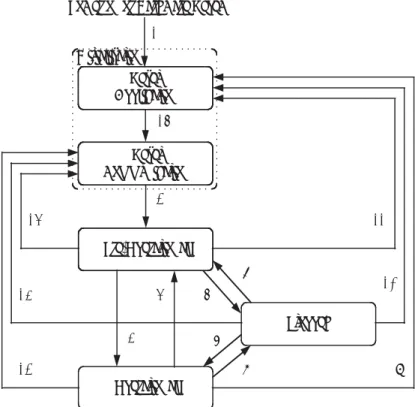
DS301 States
A generic CANopen device has various states with regard to communication. The various states differ from each other above all in the communication protocols they support. Figure 1 and table 1 represent the automatic device defined in the specification DS 301:
Figure 1 DS 301 States
Table 1 DS301 Transitions
Transition Event involving the transition
(1) On switching on, initialisation starts automatically.
(2) On completion of initialisation, the device automatically enters Pre-Operational state.
(3),(6) A "Start_Remote_Node" is received from the master (via the NMT protocol).
(4),(7) An "Enter_Pre-Operational_State" is received from the master (via the NMT protocol).
(5),(8) A "Stop_Remote_Node" is received from the master. (9),(10),(11) A "Reset_Node" is received from the master.
(12),(13),(14) A "Reset_Communication" is received from the master. (15) As soon as the "Reset_Application" phase has terminated,
"Reset_Communication" starts automatically.
Pre-Operational Operational Stopped (14) (9) (2) (3) (4) (7) (5) (8) (6) (13) (12) (10) (11) (15) Reset Communication Reset Application Power on or Hardware Reset
(1) Initialisation
The protocols supported by the various states are shown in table 2:
Table 2 Protocols supported
1.5
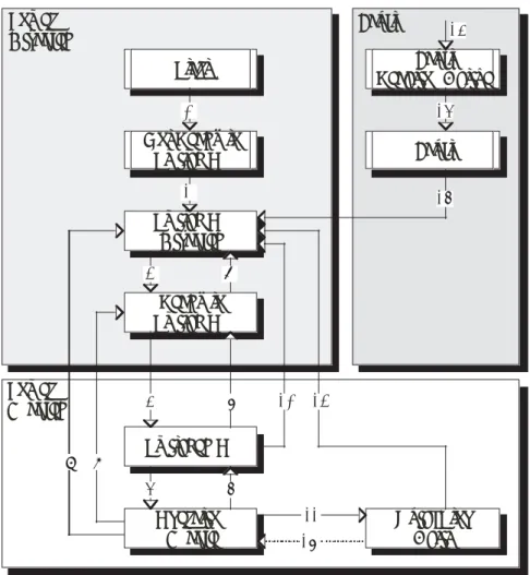
DSP 402 States
As already mentioned, the specification DSP 402 defines the "standard behaviour" of a CANopen servomotor. The states of the motor from a drive point of view are defined in the specification. The transitions automatic device is outlined in figure 2:
Figure 2 DSP 402 States
State Meaning Protocols
SDO PDO SYNC EMGCY NMT BOOTUP
Reset Application The hardware is initialised and the typical device parameters are reloaded.
X
Reset
Communication
The CANopen parameters
are reloaded from flash. X
Pre-Operational The device is operational.
X X X X
Operational The device is operational.
X X X X X
Stopped The device is in safety
mode. X 9 16 11 8 0 1 7 2 3 5 4 12 10 15 14 13
Switch On
Disabled
Start
QuickStop
Activ
Fault
Reaction Active
Not Ready to
Switch On
Ready to
Switch On
Switched On
6Operation
Enable
Fault
Fault
Power
Disabled
Power
Enabled
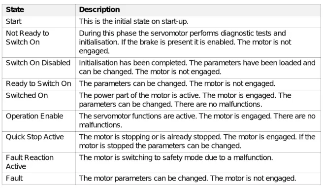
Table 3 DSP 402 States
Transitions from one state to another are determined either by motor errors or by commands sent by the master. These commands are sent using the object "Controlword" defined by DSP402. These transitions are listed in table 4:
Table 4 Commands to determine the changes in state
State Description
Start This is the initial state on start-up. Not Ready to
Switch On
During this phase the servomotor performs diagnostic tests and initialisation. If the brake is present it is enabled. The motor is not engaged.
Switch On Disabled Initialisation has been completed. The parameters have been loaded and can be changed. The motor is not engaged.
Ready to Switch On The parameters can be changed. The motor is not engaged. Switched On The power part of the motor is active. The motor is engaged. The
parameters can be changed. There are no malfunctions.
Operation Enable The servomotor functions are active. The motor is engaged. There are no malfunctions.
Quick Stop Active The motor is stopping or is already stopped. The motor is engaged. If the motor is stopped the parameters can be changed.
Fault Reaction Active
The motor is switching to safety mode due to a malfunction.
Fault The motor parameters can be changed. The motor is not engaged.
Transition Command Internal state
0 The motor is turned on.
1 The self-diagnosis and initialisation
procedures have been completed.
2 Shutdown
3 Switch On 4 Enable Operation 5 Disable Operation
6 Shutdown
7 Quick Stop or Disable Voltage
8 Shutdown
9 Disable Voltage
10 Quick Stop or Disable Voltage 11 Quick Stop
12 Disable Voltage
13 An error has occurred.
14 The motor has switched to safety mode.
15 Fault Reset 16 Operation Enable
1.6
Operating modes
The servomotor has various modes of operation, which are active during "operation enable" state and allow various activities to be carried out:
1. Resetting of the motor positions (homing mode).
2. Setting of the motor speed (profile velocity mode).
3. Setting of the motor position and speed (profile position mode).
1.7
Serial communication protocol
As regards use of Smart Motor SM137 and SM140 with the serial communication protocol, please refer to the “User Manual for SM137-SM140 motors: Serial communication protocol” distributed by CNI Engineering S.r.l.
2 Object
Dictionary
This section describes the Object Dictionary, that is to say the series of objects defined within the Smart Motor that allows commands to be send and/or dimensions such as the position and the speed to be monitored.
2.1
Definition of an object
Each object is defined using the following tables: • Object description table.
• Input description table. • Format description table. • Data description table.
2.1.1
Object description table
Index
The index of an object is defined in hexadecimal form; this can be identified by the fact that there is a lower case letter ‘h’ at the foot of the index for the object in question.
The following types of index are used:
• "1000h - 1FFFh Objects with communication profile CiA DS-301 V4.02 • "2000h - 5FFFh Objects defined by the manufacturer.
• "6000h - 9FFFh Objects with the device profile CiA DSP-402 V2.0
Object Name
Indicates the symbolic name of the object.
Object Code
One of the following object structures (Object Codes) will be assigned to all objects: • VAR: Single value, for example of the type Integer8, Unsigned32 etc.
• ARRAY: A set of data in which all the elements have the same data type. The subindex 00h determines the number of elements.
• RECORD: A set of data made up of elements of different type. The subindex 00h determines the number of elements.
Description of object Index Numerical identification for the object. Object name Symbolic name of the object.
Object code Structure of the object. Data type Type of object.
Data type
The data types that an object can have are the following:
CiA Reference
The Reference row in the definition of an object contains a reference to the CAN profile definition used in the CiA (CAN in Automation) manual.
2.1.2
Object description table
Subindex
The subindex of an object comprises a hexadecimal number identified by a lower case letter ‘h’ at the foot of the object’s subindex.
In the case of single objects (VAR), only the subindex 00h will be assigned. In the case of intervals of values (ARRAY or RECORD), the value of subindex 00h determines the size of the group of values.
Description
Indicates the name of the parameter in question.
Name Description Interval Bytes
Integer8 8 bit values -128,...,+127 1
Integer16 16 bit values -32768,...,+32767 2
Integer32 32 bit values -2147483648,...,+2147483647 4
Unsigned8 8 bit values 0,...,255 1
Unsigned16 16 bit values 0,...,65535 2
Unsigned32 32 bit values 0,...,4294967295 4
Visible string ASCII symbols 20h,...,7Eh ≤15
String of octets ASCII symbols 00h,...,FFh ≤16
Description of elements
Subindex Sequential number identifying the object from other objects with the same index.
Description Indicates the name of the parameter. Access Indicates the object’s access attribute. PDO mapping Determines whether or not the object can be
mapped in a PDO.
Unit Indicates the unit of measurement for the object. Interval of values Indicates the interval of values for the object. Preset value Indicates the preset value of the object. Recordable Indicates whether or not the object can be
Access
An access attribute will be assigned for each object:
PDO mapping
The “PDO mapping” line of an object in input indicates whether or not the parameter can be mapped within a PDO (Process Data Object).
Unit of measurement
The physical unit for parameters must be defined explicitly for each object (Unit). • The positions are expressed in counts [cnt]
• The speeds are expressed in rpm [rpm]
• The accelerations are expressed in revs per second squared divided by 10000 [r/s2/10000] • The currents are expressed in Ampere multiplied by 100 [Ax100]
• PI regulator gains are pure numbers multiplied by 100 [x100]
Interval of values
The interval of values for an object is restricted by the type of data, unless the interval of values allowed is not stated explicitly.
Preset value
All devices are supplied with preset parameter values (values on delivery or factory values). The operator can adjust modifiable parameters for his application, and then record them in the non volatile memory.
Recordable
The “Recordable” line indicates whether or not the object can be recorded in the non volatile memory.
Value Description
rw The value of the object is both readable and writable. ro The value of the object is read-only.
wo The value of the object is write-only. const Read-only access, the value is constant.
3
Object Dictionary DS 301
3.1
Object 1000
h: Device Type
Object 1000h describes the Device Type and the device profile applied.
.
3.2
Object 1001
h: Error Register
Object 1001h is an error register for the device.
.
Description of object
Index 1000h
Object name Device Type Object code VAR
Data type Unsigned32
Reference CiA DS-301 V4.04, page 86; CiA DSP-402 V2.0, page 24
Description of elements
Subindex 00h
Description Device type Access ro (read-only)
PDO mapping No
Unit
-Interval of values Unsigned32 Preset value 00020192h
Recordable No
Description of format
Bit 31 - 24 Not used
Bit 23 - 16 Inverter type (Bit 17 = 1: servo-driven) Bit 15 - 0 Device CiA profile (0192h=402)
Description of object
Index 1001h
Object name Error Register Object code VAR
Data type Unsigned8
Reference CiA DS-301 V4.02, page 87; CiA DSP-402 V2.0, page 24
3.3
Object 1002
h:Manufacturer Status Register
Object 1002h is a status register for element customised by the manufacturer.
.
Description of elements
Subindex 00h
Description Error register Access ro (read-only)
PDO mapping No
Unit
-Interval of values Unsigned8 Preset value 0
Recordable Yes
Description of format
Bit 7 Specific to manufacturer. Bit 6 Reserved (always 0).
Bit 5 Specific to device CiA profile.
Bit 4 Communication error (overrun, error state).
Bit 3 Temperature.
Bit 2 Power.
Bit 1 Current.
Bit 0 Generic error.
Description of object
Index 1002h
Object name Manufacturer Status Register Object code VAR
Data type Unsigned32
Reference CiA DS-301 V4.0, pages 9-65
Description of elements
Subindex 00h
Description Manufacturer status register Access ro (read-only)
PDO mapping No
Unit
-Interval of values Unsigned32 Preset value 0
3.4
Object 1008
h: Manufacturer Device Name
The object with index 1008h contains the device name assigned by the manufacturer.
.
3.5
Object 1009
h: Manufacturer Hardware Version
The object with index 1009h contains the description of the hardware version assigned by the manufacturer.
.
Description of object
Index 1008h
Object name Manufacturer Device Name Object code VAR
Data type Visible string
Reference CiA DS-301 V4.02, page 91
Description of elements
Subindex 00h
Description Device name
Access const
PDO mapping No
Unit
-Interval of values Visible string (≤15 characters) Preset value SM137
Recordable No
Description of object
Index 1009h
Object name Manufacturer Hardware Version Object code VAR
Data type Visible String
Reference CiA DS-301 V4.02, page 91
Description of elements
Subindex 00h
Description Manufacturer hardware version
Access const
PDO mapping No
Unit
-Interval of values Visible string (≤15 characters) Preset value P137C
3.6
Object 100A
h: Manufacturer Software Version
The object with index 100Ah contains the description of the software version loaded on the device.
Description of object
Index 100Ah
Object name Manufacturer Software Version Object code VAR
Data type Visible String
Reference CiA DS-301 V4.02, page 91
Description of elements
Subindex 00h
Description Software version
Access const
PDO mapping No
Unit
-Interval of values Visible string (≤15 characters) Preset value Currently 00120 or 00123
3.7
Object 100C
h: Guard Time
The objects with indexes 100Ch and 100Dh include the Guard Time in milliseconds and the Life Time Factor. The Life Time Factor multiplied by the Guard Time gives the maximum interval for the Life Guarding Protocol: if, within this time, the peripheral device (NMT-Slave) does not receive Node Guarding packages from the Master, the peripheral device will revert to safety mode. This has a value of 0 if Node Guarding (surveillance of the CANopen node) is disabled.
By means of the Node Guarding protocol, an NMT-Master supervises communication with the peripheral devices (NMT-Slaves). The Guard time is indicated in milliseconds.
Description of object
Index 100Ch
Object name Guard Time Object code VAR Data type Unsigned16
Reference CiA DS-301 V4.02, page 92
Description of elements
Subindex 00h
Description Peripheral device watch-dog Access rw (read/write)
PDO mapping No
Unit milliseconds
Interval of values Unsigned16 Preset value 0
3.8
Object 100D
h: Life Time Factor
The object with index 100Dh regulates the Life Time for Life-Guarding.
The Life Time Factor multiplied by the Cycle Time of the Guard Time (object 100Ch peripheral device watch-dog) gives the Life Time. The Life Time Factor is set to 0 if it is not used
The reaction of the SmartMotor to a loss of connection with the NMT-Master (Life Guarding Event), can be regulated using object 6007h (Abort Connection Option Code)*.
* Object 6007
h (Abort Connection Option Code) is currently not implemented. The behaviour of the motor is Description of
object
Index 100Dh
Object name Life Time Factor Object code VAR
Data type Unsigned8
Reference CiA DS-301 V4.02, page 92
Description of elements
Subindex 00h
Description Life time factor Access rw (read/write)
PDO mapping No
Unit
-Interval of values Unsigned8 Preset value 0
3.9
Object 1010
h: Store Parameters
The object with index 1010h allows the parameters to be stored in a non volatile memory. To avoid parameter storage errors, storage only takes place when a specific code is entered in the
appropriate subindex. This code is "save". By writing the expression 'save' in the subindex, the current parameter values are saved to the non volatile memory and are therefore available when the device is turned on again (Power-On Defaults).
WARNING: The parameters are saved to the processor’s Flash memory! The number of save operations that can be performed is therefore limited..
Description of object
Index 1010h
Object name Store Parameters Object code ARRAY
Data type Unsigned32
Reference CiA DS-301 V4.02, page 92
Description of elements
Subindex 00h
Description Maximum subindex supported Access ro (read-only)
PDO mapping No
Unit
-Interval of values Unsigned8: 1 - 255 Preset value 1
Recordable No
Subindex 01h
Description Save all parameters Access rw (read/write)
PDO mapping No
Unit
-Interval of values Unsigned32 Preset value 1 Recordable No Description of format Subindex 01h(Read access) Bit 31 - 2 reserved
Bit 1 0= device does not save the parameters independently 1= device saves the parameters independently
Bit 0 0= device does not save the parameters on command 1= device saves the parameters on command
Description of format Subindex 01h(Write access)
Bit 31 - 24 65h = 'e’ (ASCII characters, ISO 8859) Bit 23 - 16 76h = 'v' (ASCII characters, ISO 8859) Bit 15 - 8 61h = 'a' (ASCII characters, ISO 8859) Bit 7 - 0 73h = 's' (ASCII characters, ISO 8859)
3.10
Object 1011
h: Restore Parameters
The object with index 1011h is used to restore the parameter values preset by the manufacturer according to the communication or profile of the device. During read access, the device provides information on its ability to regenerate these values.
By writing the instruction ‘load’ in the subindex, the factory settings for the corresponding parameters will be restored, and the factory settings will be restored as the current parameter values after the command “NMT Reset Node” has been performed or after the peripheral device has been turned off and then on again. These parameters can be saved in the permanent memory, and they will be available as Power-On Defaults.
Description of object
Index 1011h
Object name Restore Default Parameters Object code ARRAY
Data type Unsigned32
Reference CiA DS-301 V4.02, pages 9-72
Description of elements
Subindex 00h
Description Maximum subindex supported Access ro (read-only)
PDO mapping No
Unit
-Interval of values Unsigned8: 1 Preset value 1
Recordable No
Subindex 01h
Description Restore all preset parameter values. Access rw (read/write)
PDO mapping No
Unit
-Interval of values Unsigned32 Preset value 1 Recordable No Description of format Subindex 01h (Read Access) Bit 31 - 1 reserved
Bit 0 0= the device does not restore the parameters 1= the device restores the parameters
Description of format Subindex 01h (Write Access)
Bit 31 - 24 64h = 'd’ (ASCII characters, ISO 8859) Bit 23 - 16 61h = 'a' (ASCII characters, ISO 8859) Bit 15 - 8 6Fh = 'o' (ASCII characters, ISO 8859) Bit 7 - 0 6Ch = 'l' (ASCII characters, ISO 8859)
3.11
Object 1014
h: COB-ID Emergency Message
The object 1014h defines the COB-ID for the object Emergency (EMCY).Using the object Emergency, the errors are communicated to the Master at the time they occur. An emergency message is made up of 8 bytes and has the following structure:
The emergency error codes used are the ones described in the chapter “Emergency Messages” provided herein.
Description of object
Index 1014h
Object name COB-ID Emergency Message Object code VAR
Data type Unsigned32
Reference CiA DS-301 V4.02, page 98
Description of elements
Subindex 00h
Description COB-ID of the emergency message (EMCY) Access rw (read/write)
PDO mapping No
Unit
-Interval of values Unsigned32 Preset value 80h + Node-ID
Recordable Yes
Description of format
Bit 31 0 = EMCY exists / is valid
1 = EMCY does not exist / is not valid Bit 30 Reserved (always 0)
Bit 29 0 = 11-bit identifiers (CAN 2.0A) 1 = 29-bit identifiers (CAN2.0B)
Bit 28 - 11 if bit 29=1, identify bits 28-11 of the 29-bit Bit 10-0 Bits 10-0 of the COB-ID
Byte 0 - 1 Emergency Error Code Byte 2 Object 1001h: Error Register
3.12
Object 1400
h: 1
stReceive PDO Parameter
The object 1400h allows customisation of the communication parameters for the first receive PDO (RPDO1).
Description of object
Index 1400h
Object name 1st Receive PDO Parameter
Object code RECORD
Data type PDO CommonPar
Reference CiA DS-301 V4.02, page 107; CiA DS-402 V2.0, page 25
Description of elements
Subindex 00h
Description Maximum subindex supported Access ro (read-only)
PDO mapping No
Unit
-Interval of values Unsigned8: 2 - 5 Preset value 2
Recordable No
Subindex 01h
Description COB-ID used by the PDO Access rw (read/write)
PDO mapping No
Unit
-Interval of values Unsigned32
Preset value 40000200h + Node-ID
Recordable Yes
Subindex 02h
Description Transmission type Access rw (read/write)
PDO mapping No
Unit
-Interval of values Unsigned8 Preset value 255
Receive PDOs are only processed in a state of NMT OPERATIONAL.
The PDO communication parameters can only be changed in a state of NMT PRE-OPERATIONAL.
Description of format Subindex 01h
Bit 31 0 = PDO valid
1 = PDO not valid
Bit 30 0 = RTR allowed on this PDO 1 = RTR not allowed on this PDO Bit 29 0 = 11-bit identifiers (CAN 2.0A)
1 = 29-bit identifiers (CAN 2.0B)
Bit 28 - 11 if bit 29=1, identify bits 28-11 of the 29-bit Bit 10 - 0 Bits 10-0 of the COB-ID
Description of data
Subindex 02h
0 synchronous: RPDO1 is synchronised by the next SYNC 1,...,240 synchronous: same function as value 0
241,...,251 reserved
252 not allowed in receive PDOs 253 not allowed in receive PDOs 254 asynchronous: same value as 255
255 asynchronous: RPDO1 is immediately active (straight after receiving) (preset)
3.13
Object 1401
h: 2
ndReceive PDO Parameter
The object 1401h allows customisation of the communication parameters for the second receive PDO (RPDO2) (see also paragraph 3.12 object 1400h: 1st Receive PDO Parameter).
Description of object
Index 1401h
Object name 2nd Receive PDO Parameter
Object code RECORD
Data type PDO CommonPar
Reference CiA DS-301 V4.02, page 107; CiA DS-402 V2.0, page 25 Description of
elements
Subindex 00h
Description Maximum subindex supported Access ro (read-only)
PDO mapping No
Unit
-Interval of values Unsigned8: 2 - 5 Preset value 2
Recordable No
Subindex 01h
Description COB-ID used by the PDO Access rw (read/write)
PDO mapping No
Unit
-Interval of values Unsigned32
Preset value 40000300h + Node-ID
Recordable Yes
Subindex 02h
Description Transmission type Access rw (read/write)
PDO mapping No
Unit
-Interval of values Unsigned8 Preset value 255
Description of format Subindex 01h
Bit 31 0 = PDO valid
1 = PDO not valid
Bit 30 0 = RTR allowed on this PDO 1 = RTR not allowed on this PDO Bit 29 0 = 11-bit identifiers (CAN 2.0A)
1 = 29-bit identifiers (CAN 2.0B)
Bit 28 - 11 if bit 29=1, identify bits 28-11 of the 29-bit Bit 10 - 0 Bits 10-0 of the COB-ID
Description of data
Subindex 02h
0 synchronous: RPDO2 is synchronised by the next SYNC 1,...,240 synchronous: same function as value 0
241,...,251 reserved
252 not allowed in receive PDOs 253 not allowed in receive PDOs 254 asynchronous: same value as 255
255 asynchronous: RPDO2 is immediately active (straight after receiving) (preset)
3.14
Object 1600
h: 1
stReceive PDO Mapping Parameter
The object with index 1600h contains the mapping for the PDOs that the device is enabled to receive.
Description of object
Index 1600h
Object name 1st Receive PDO Mapping Parameter
Object code RECORD
Data type PDO mapping
Reference CiA DS-301 V4.02, page 109; CiA DS-402 V2.0, page 25
Description of elements
Subindex 00h
Description Number of mapped objects requested in PDO Access rw (read/write)
PDO mapping No
Unit
-Interval of values Unsigned8: 1 - 8 Preset value 1
Recordable Yes
Subindex 01h
Description First object mapped Access rw (read/write)
PDO mapping No
Unit
-Interval of values Unsigned32 Preset value 60400010h
Recordable Yes
Subindex 02h
Description Second object mapped Access rw (read/write)
PDO mapping No
Unit
-Interval of values Unsigned32 Preset value 0h
Description of elements
Subindex 03h
Description Third object mapped Access rw (read/write)
PDO mapping No
Unit
-Interval of values Unsigned32 Preset value 0h
Recordable Yes
Subindex 04h
Description Fourth object mapped Access rw (read/write)
PDO mapping No
Unit
-Interval of values Unsigned32 Preset value 0h
Recordable Yes
Subindex 05h
Description Fifth object mapped Access rw (read/write)
PDO mapping No
Unit
-Interval of values Unsigned32 Preset value 0h
Recordable Yes
Subindex 06h
Description Sixth object mapped Access rw (read/write)
PDO mapping No
Unit
-Interval of values Unsigned32 Preset value 0h
Recordable Yes
Subindex 07h
Description Seventh object mapped Access rw (read/write)
PDO mapping No
-PDO mapping is dynamic: it is possible to define which objects are mapped within the -PDO. This mapping can only be carried out in Pre-operational state.
For example, if in the 1st PDO you wish to receive not only the Controlword (6040h), but also the objects Mode of Operation (6060h) and Target position (607Ah) it will be necessary to:
read the value of the object 1400h;
1. in the value read set bit 31 to 1 so as to invalidate the 1st PDO in receive. Send the value calculated to object 1400h;
2. in object 1600h subindex 00h write the value 0 to indicate that no object is mapped;
3. in object 1600h subindex 01h write the value 60400010h to indicate that the first mapped object is the Controlword (address 6040h subindex 00h) with a length of 16 bit (2 byte);
4. in object 1600h subindex 02h write the value 60600008h to indicate that the second mapped object is the Mode of Operation (address 6060h subindex 00h) with a length of 8 bit (1 byte);
5. in object 1600h subindex 03h write the value 607A0020h to indicate that the third mapped object is the Target Position (address 607Ah subindex 00h) with a length of 32 bit (4 byte);
6. Enable the PDO again by setting bit 31 in object 1400h to 0. Description of
elements
Subindex 08h
Description Eighth object mapped Access rw (read/write)
PDO mapping No
Unit
-Interval of values Unsigned32 Preset value 0h Recordable Yes Description of format Subindex 01h - 08h
Bit 31 - 16 index of the object to be mapped (16 bit) Bit 16 - 8 subindex of the object to be mapped (8 bit) Bit 7 - 0 length of the object in bits (8 bit)
3.15
Object 1601
h: 2
ndReceive PDO Mapping Parameter
The object with index 1601h contains the mapping for the PDO that the device is enabled to receive (see also paragraph 3.14 object 1600h: 1st Receive PDO Mapping Parameter).
Description of object
Index 1601h
Object name 2nd Receive PDO Mapping
Object code RECORD
Data type PDO mapping
Reference CiA DS-301 V4.02, page 109; CiA DS-402 V2.0, page 25
Description of elements
Subindex 00h
Description Number of mapped objects requested in the PDO Access rw (read/write)
PDO mapping No
Unit
-Interval of values Unsigned8: 1 - 8 Preset value 1
Recordable Yes
Subindex 01h
Description First object mapped Access rw (read/write)
PDO mapping No
Unit
-Interval of values Unsigned32 Preset value 60400010h
Recordable Yes
Subindex 02h
Description Second object mapped Access rw (read/write)
PDO mapping No
Unit
-Interval of values Unsigned32 Preset value 6060008h
Recordable Yes
Subindex 03h
Description Third object mapped Access rw (read/write)
PDO mapping No
Unit
-Interval of values Unsigned32 Preset value 0h
Recordable Yes
Subindex 04h
Description Fourth object mapped Access rw (read/write)
PDO mapping No
-Description of elements
Subindex 05h
Description Fifth object mapped Access rw (read/write)
PDO mapping No
Unit
-Interval of values Unsigned32 Preset value 0h
Recordable Yes
Subindex 06h
Description Sixth object mapped Access rw (read/write)
PDO mapping No
Unit
-Interval of values Unsigned32 Preset value 0h
Recordable Yes
Subindex 07h
Description Seventh object mapped Access rw (read/write)
PDO mapping No
Unit
-Interval of values Unsigned32 Preset value 0h
Recordable Yes
Subindex 08h
Description Eighth object mapped Access rw (read/write)
PDO mapping No
Unit
-Interval of values Unsigned32 Preset value 0h Recordable Yes Description of format Subindex 01h - 08h
Bit 31 - 16 index of the object to be mapped (16 bit) Bit 16 - 8 subindex of the object to be mapped (8 bit) Bit 7 - 0 length of the object in bits (8 bit)
PDO mapping is dynamic: it is possible to define which objects are mapped within the PDO. This mapping can only be carried out in Pre-operational state.
3.16
Object 1800
h: 1st Transmit PDO Parameter
The object 1800h is used to customise the communication parameters for the first transmit PDO.
Description of object
Index 1800h
Object name 1st Transmit PDO Parameter
Object code RECORD
Data type PDO CommPar
Reference CiA DS-301 V4.02, page 111; CiA DS-402 V2.0, page 29
Description of elements
Subindex 00h
Description Maximum subindex supported Access ro (read/only)
PDO mapping No
Unit
-Interval of values Unsigned8: 2 - 5 Preset value 5
Recordable No
Subindex 01h
Description COB-ID used by the PDO Access rw (read/write)
PDO mapping No
Unit
-Interval of values Unsigned32
Preset value 40000180h + Node-ID
Recordable Yes
Subindex 02h
Description Transmission type Access rw (read/write)
PDO mapping No
Unit
-Interval of values Unsigned8 Preset value 255
The parameter Inhibit Time represents the minimum time (in steps of 100 microseconds) between two successive PDO transmits.
The parameter Event Timer involves a fixed time PDO transmit (prescribed by the parameter in milliseconds) even if the values of the mapped objects have not changed.
The PDO transmit will only take place in NMT OPERATIONAL state. The PDO communication parameters can only be changed in NMT PRE-OPERATIONAL state.
Description of elements
Subindex 03h
Description PDO inhibition time Access rw (read/write)
PDO mapping No
Unit multiples of 100 microseconds Interval of values Unsigned16
Preset value 0
Recordable Yes
Subindex 05h
Description Event time interval Access rw (read/write)
PDO mapping No
Unit milliseconds
Interval of values Unsigned16 Preset value 0
Recordable Yes
Description of format Subindex 01h
Bit 31 0 = PDO valid
1 = PDO not valid
Bit 30 0 = RTR allowed on this PDO 1 = RTR not allowed on this PDO Bit 29 0 = 11-bit identifiers (CAN 2.0A)
1 = 29-bit identifiers (CAN 2.0B)
Bit 28 - 11 if bit 29=1, identify bits 28-11 of the 29-bit Bit 10 - 0 Bits 10-0 of the COB-ID
Description of data
Subindex 02h
0 synchronous acyclic, data updated on previous SYNC 1,...,240 synchronous cyclic, data updated on previous SYNC 241,...,251 reserved
252 synchronous on request, data is updated on previous SYNC
253 asynchronous on request, data is updated immediately on SYNC
254 asynchronous: identical to value 255
255 asynchronous transmitted simultaneously to variation of one of the mapped objects or on expiry of the Event Timer (preset)
3.17
Object 1801
h: 2
ndTransmit PDO Parameter
Object 1801h is used to customise the communication parameters for the second transmit PDO (see also paragraph 3.16 object 1800h: 1st Transmit PDO Parameter).
Description of object
Index 1801h
Object name 2nd Transmit PDO Parameter
Object code RECORD
Data type PDO CommPar
Reference CiA DS-301 V4.02, page 111; CiA DS-402 V2.0, page 29
Description of elements
Subindex 00h
Description Maximum subindex supported Access ro (read/only)
PDO mapping No
Unit
-Interval of values Unsigned8: 2 - 5 Preset value 5
Recordable No
Subindex 01h
Description COB-ID used by the PDO Access rw (read/write)
PDO mapping No
Unit
-Interval of values Unsigned32
Preset value 40000280h + Node-ID
Recordable Yes
Subindex 02h
Description Transmission type Access rw (read/write)
PDO mapping No
Unit
-Interval of values Unsigned8 Preset value 255
The parameter Inhibit Time represents the minimum time (in steps of 100 microseconds) between two successive PDO transmits.
The parameter Event Timer involves a fixed time PDO transmit (prescribed by the parameter in milliseconds) even if the values of the mapped objects have not changed. The PDO transmit will only take place in NMT OPERATIONAL state. The PDO communication parameters can only be changed in NMT PRE-OPERATIONAL state.
Description of elements
Subindex 03h
Description PDO inhibition time Access rw (read/write)
PDO mapping No
Unit multiples of 100 microseconds Interval of values Unsigned16
Preset value 0
Recordable Yes
Subindex 05h
Description Event time interval Access rw (read/write)
PDO mapping No
Unit milliseconds
Interval of values Unsigned16 Preset value 0
Recordable Yes
Description of format Subindex 01h
Bit 31 0 = PDO valid
1 = PDO not valid
Bit 30 0 = RTR allowed on this PDO 1 = RTR not allowed on this PDO Bit 29 0 = 11-bit identifiers (CAN 2.0A)
1 = 29-bit identifiers (CAN 2.0B)
Bit 28 - 11 if bit 29=1, identify bits 28-11 of the 29-bit Bit 10 - 0 Bits 10-0 of the COB-ID
Description of data
Subindex 02h
0 synchronous acyclic, data updated on previous SYNC 1,...,240 synchronous cyclic, data updated on previous SYNC 241,...,251 reserved
252 synchronous on request, data is updated on previous SYNC
253 asynchronous on request, data is updated immediately on SYNC
254 asynchronous: identical to value 255
255 asynchronous transmitted simultaneously to variation of one of the mapped objects or on expiry of the Event Timer (preset)
3.18
Object 1A00
h: 1
stTransmit PDO Mapping Parameter
The object 1A00h contains the mapping for the first transmit PDO.Description of object
Index 1A00h
Object name 1st Transmit PDO Mapping Parameter
Object code RECORD
Data type PDO mapping
Reference CiA DS-301 V4.02, page 112; CiA DS-402 V2.0, page 29
Description of elements
Subindex 00h
Description Number of objects mapped in the first transmit PDO Access rw (read/write)
PDO mapping No
Unit
-Interval of values Unsigned8: 1 - 8 Preset value 1
Recordable Yes
Subindex 01h
Description First object mapped Access rw (read/write)
PDO mapping No
Unit
-Interval of values Unsigned32 Preset value 60410010h
Recordable Yes
Subindex 02h
Description Second object mapped Access rw (read/write)
PDO mapping No
Unit
-Interval of values Unsigned32 Preset value 0h
Description of elements
Subindex 03h
Description Third object mapped Access rw (read/write)
PDO mapping No
Unit
-Interval of values Unsigned32 Preset value 0h
Recordable Yes
Subindex 04h
Description Fourth object mapped Access rw (read/write)
PDO mapping No
Unit
-Interval of values Unsigned32 Preset value 0h
Recordable Yes
Subindex 05h
Description Fifth object mapped Access rw (read/write)
PDO mapping No
Unit
-Interval of values Unsigned32 Preset value 0h
Recordable Yes
Subindex 06h
Description Sixth object mapped Access rw (read/write)
PDO mapping No
Unit
-Interval of values Unsigned32 Preset value 0h
Recordable Yes
Subindex 07h
Description Seventh object mapped Access rw (read/write)
PDO mapping No
-PDO mapping is dynamic: it is possible to define which objects are mapped within the -PDO (see also paragraph 3.12 object 1400h: 1st Receive PDO Parameter). This mapping can only be carried out in Pre-operational state.
Description of elements
Subindex 08h
Description Eighth object mapped Access rw (read/write)
PDO mapping No
Unit
-Interval of values Unsigned32 Preset value 0h Recordable Yes Description of format Subindex 01h - 08h
Bit 31 - 16 index (16 bit) Bit 16 - 8 subindex (8 bit) Bit 7 - 0 length (8 bit)
3.19
Object 1A01
h: 2nd Transmit PDO Mapping Parameter
The object 1A01h contains the mapping for the second transmit PDO.Description of object
Index 1A01h
Object name 2nd Transmit PDO Mapping Parameter
Object code RECORD
Data type PDO mapping
Reference CiA DS-301 V4.02, page 112; CiA DS-402 V2.0, page 29
Description of elements
Subindex 00h
Description Number of objects mapped in the second transmit PDO Access rw (read/write)
PDO mapping No
Unit
-Interval of values Unsigned8: 1 - 8 Preset value 2
Recordable Yes
Subindex 01h
Description First object mapped Access rw (read/write)
PDO mapping No
Unit
-Interval of values Unsigned32 Preset value 60410010h
Description of elements
Subindex 02h
Description Secondobject mapped Access rw (read/write)
PDO mapping No
Unit
-Interval of values Unsigned32 Preset value 6061008h
Recordable Yes
Subindex 03h
Description Third object mapped Access rw (read/write)
PDO mapping No
Unit
-Interval of values Unsigned32 Preset value 0h
Recordable Yes
Subindex 04h
Description Fourth object mapped Access rw (read/write)
PDO mapping No
Unit
-Interval of values Unsigned32 Preset value 0h
Recordable Yes
Subindex 05h
Description Fifth object mapped Access rw (read/write)
PDO mapping No
Unit
-Interval of values Unsigned32 Preset value 0h
Recordable Yes
Subindex 06h
Description Sixth object mapped Access rw (read/write)
PDO mapping No
-PDO mapping is dynamic: it is possible to define which objects are mapped within the -PDO (see also paragraph 3.12 object 1400h: 1st Receive PDO Parameter). This mapping can only be carried out in Pre-operational state.
Description of elements
Subindex 07h
Description Seventh object mapped Access rw (read/write)
PDO mapping No
Unit
-Interval of values Unsigned32 Preset value 0h
Recordable Yes
Subindex 08h
Description Eighth object mapped Access rw (read/write)
PDO mapping No
Unit
-Interval of values Unsigned32 Preset value 0h Recordable Yes Description of format Subindex 01h - 08h
Bit 31 - 16 index of the object to be mapped (16 bit) Bit 16 - 8 subindex of the object to be mapped (8 bit) Bit 7 - 0 length of the object in bits (8 bit)
4 Object
Dictionary:
objects
defined by the manufacturer
The first section of this chapter (objects in the interval 2000h - 2FFFh) is dedicated to the internal drive parameters. The second section (objects 3000h - 3FFFh) contains those objects dedicated to sending special low level commands.4.1
Object 2000
h: Proportional Gain of Current Loop
The object 2000h is the proportional gain of the current regulation loop.
4.2
Object 2001
h: Integral Gain of Current Loop
The object 2000h is the integral gain of the current regulation loop. Description of
object
Index 2000h
Object name Proportional Gain of Current Loop Object code VAR
Data type Integer16
Description of elements
Subindex 00h
Description Proportional gain of the current regulation loop. Access rw (read/write)
PDO mapping No
Unit x 0,01
Interval of values Integer16: 0 - 32767
Preset value 30 on SM137, 40 on SM140
Recordable Yes
Description of object
Index 2001h
Object name Integral Gain of Current Loop Object code VAR
Data type Integer16
Description of elements
Subindex 00h
Description Integral gain of the current regulation loop. Access rw (read/write)
PDO mapping No
Unit x 0,01
Interval of values Integer16: 0 - 32767
Preset value 12 on SM137, 10 on SM140
4.3
Object 2004
h: Maximum Value of Current Loop Output
The object 2004h is the maximum absolute value of the current regulation loop output.4.4
Object 2005
h: Proportional Gain of Speed Loop
The object 2005h is the proportional gain of the speed regulation loop. Description of
object
Index 2004h
Object name Maximum value of current loop output Object code VAR
Data type Integer16
Description of elements
Subindex 00h
Description Maximum value of the current regulation loop output. Access rw (read/write)
PDO mapping No
Unit Volt x 0,1
Interval of values Integer16: 1 - 193 on SM137, : 1 -195 on SM140 Preset value 193 on SM137, 195 on SM140
Recordable Yes
Description of object
Index 2005h
Object name Proportional Gain of Speed Loop Object code VAR
Data type Integer16
Description of elements
Subindex 00h
Description Proportional gain of the speed regulation loop. Access rw (read/write)
PDO mapping No
Unit x 0,01
Interval of values Integer16: 0 - 32767
Preset value 150 on SM137, 600 on SM140
4.5
Object 2006
h: Integral Gain of Speed Loop
The object 2006h is the integral gain of the speed regulation loop.4.6
Object 2007
h: Percentage Feedforward for Speed Loop
The object 2007h is the percentage feedforward for the speed regulator. Description of
object
Index 2006h
Object name Integral Gain of Speed Loop Object code VAR
Data type Integer16
Description of elements
Subindex 00h
Description Integral gain of the speed regulation loop. Access rw (read/write)
PDO mapping No
Unit x 0,01
Interval of values Integer16: 0 - 32767
Preset value 10 on SM137, 50 on SM140
Recordable Yes
Description of object
Index 2007h
Object name Percentage Feedforward for Speed Loop Object code VAR
Data type Integer16
Description of elements
Subindex 00h
Description Percentage feedforward for the speed regulator. Access rw (read/write)
PDO mapping No
Unit %
Interval of values Integer16: 0 - 100 Preset value 100
4.7
Object 2009
h: Maximum Value of Speed Loop Output
The object 2009h is the absolute maximum value of the speed regulation loop output.4.8
Object 200A
h: Proportional Gain of Position Loop
The object 200Ah is the proportional gain of the position regulation loop. Description of
object
Index 2009h
Object name Maximum value of speed loop output Object code VAR
Data type Integer16
Description of elements
Subindex 00h
Description Absolute maximum value of the speed regulation loop output.
Access rw (read/write)
PDO mapping No
Unit Ampere x 0,01
Interval of values Integer16: 1 - 900 on SM137, : 1 - 3500 on SM140 Preset value 500 on SM137, 1800 on SM140
Recordable Yes
Description of object
Index 200Ah
Object name Proportional Gain of position Loop Object code VAR
Data type Integer16
Description of elements
Subindex 00h
Description Proportional gain of the position loop Access rw (read/write)
PDO mapping No
Unit x 0,01
Interval of values Integer16: 0 - 32767 Preset value 500
4.9
Object 200B
h: Integral Gain of Position Loop
The object 200Bh is the integral gain of the position regulation loop.4.10
Object 200C
h: Percentage Feedforward for Position Loop
The object 200Ch is the percentage feedforward for the position regulator. Description of
object
Index 200Bh
Object name Integral Gain of position Loop Object code VAR
Data type Integer16
Description of elements
Subindex 00h
Description Integral gain of the position loop. Access rw (read/write)
PDO mapping No
Unit x 0,01
Interval of values Integer16: 0 - 32767 Preset value 0
Recordable Yes
Description of object
Index 200Ch
Object name Percentage Feedforward for position Loop Object code VAR
Data type Integer16
Description of elements
Subindex 00h
Description Percentage feedforward for the position regulator. Access rw (read/write)
PDO mapping No
Unit %
Interval of values Integer16: 0 - 100 Preset value 100
4.11
Object 200E
h: Maximum Value of Position Loop Output
The object 200Eh is the absolute maximum value of the position regulation loop output.4.12
Object 200F
h: Maximum Speed Following Error
Object 200Fh is the maximum speed following error which, when exceeded for a time longer than that foreseen in object 2010h, will switch the motor to Fault. If the value is 0 the speed following error control is disabled.
Description of object
Index 200Eh
Object name Maximum value of position loop output Object code VAR
Data type Integer16
Description of elements
Subindex 00h
Description Absolute maximum value of the position loop output. Access rw (read/write)
PDO mapping No
Unit rpm
Interval of values Integer16: 1 - 8000 Preset value 4500
Recordable Yes
Description of object
Index 200Fh
Object name Maximum Speed Following Error Object code VAR
Data type Integer16
Description of elements
Subindex 00h
Description Maximum speed following error allowed Access rw (read/write)
PDO mapping No
Unit rpm
Interval of values Integer16: 0 - 8000 Preset value 0
4.13
Object 2010
h: Maximum Duration of Speed Following Error
The object 2010h is the time for which the speed following error must continually exceed the value foreseen in object 200Fh, in order to switch the motor to Fault.
4.14
Object 2011
h: Maximum Torque
The object 2011h is the maximum torque required from the speed regulator. If this is exceeded in a continuous manner for longer than foreseen in object 2012h, the motor will switch to Fault.
Description of object
Index 2010h
Object name Maximum Duration of Speed Following Error Object code VAR
Data type Integer16
Description of elements
Subindex 00h
Description Maximum duration of the speed following error. Access rw (read/write)
PDO mapping No
Unit Msec
Interval of values Integer16: 0 - 10000 Preset value 0
Recordable Yes
Description of object
Index 2011h
Object name Maximum torque Object code VAR
Data type Integer16
Description of elements
Subindex 00h
Description Maximum torque Access rw (read/write)
PDO mapping No
Unit Ampere x 0,01
Interval of values Integer16: 0 - 900 on SM137, :35 on SM140 Preset value 250 on SM137, 900 on SM140
4.15
Object 2012
h: Timeout for Maximum Torque
The object 2012h is the time during which the speed regulator torque must continuously exceed the one foreseen in object 2011h in order to switch the motor to Fault.
4.16
Object 2013
h: Bit_A
The object 2013h contains 16 bits, the meanings of which are given in paragraph 4.25. Description of
object
Index 2012h
Object name Timeout for Maximum Torque Object code VAR
Data type Integer16
Description of elements
Subindex 00h
Description Timeout for maximum torque Access rw (read/write)
PDO mapping No
Unit msec
Interval of values Integer16: 0 - 10000 Preset value 1000
Recordable Yes
Description of object
Index 2013h
Object name Bit_A Object code VAR Data type Integer16 Reference Paragraph 4.25 Description of elements Subindex 00h Description Bit_A Access rw (read/write) PDO mapping No Unit
-Interval of values Integer16 Preset value 1
4.17
Object 2014
h: Electric Angle On Zero Index
The object 2014h is reserved for internal use.4.18
Object 2015
h: First Component of Speed Loop Feedforward
The object 2015h is the first component of the speed regulator feedforward. Description of
object
Index 2014h
Object name Electric Angle On Zero Index Object code VAR
Data type Integer16
Description of elements
Subindex 00h
Description Electric Angle On Zero Index Access rw (read/write)
PDO mapping No
Unit
-Interval of values Integer16: 0 - 799 on SM137, 0 - 1999 on SM140 Preset value
-Recordable Yes
Description of object
Index 2015h
Object name First Component of Speed Loop Feedforward Object code VAR
Data type Integer16
Description of elements
Subindex 00h
Description First component in the speed regulator feedforward Access rw (read/write)
PDO mapping No
Unit
-Interval of values Integer16: 0 - 32767
Preset value 600 on SM137, 300 on SM140
4.19
Object 2016
h: Second Component of Speed Loop Feedforward
The object 2016h is the second component of the speed regulator feedforward, the one relating to friction.4.20
Object 2017
h: Third Component of Speed Loop Feedforward
The object 2017h is the third component of the speed regulator feedforward, the one that is proportional to the speed.
Description of object
Index 2016h
Object name Second Component of Speed Loop Feedforward Object code VAR
Data type Integer16
Description of elements
Subindex 00h
Description Second component of the speed regulator feedforward. Access rw (read/write)
PDO mapping No
Unit
-Interval of values Integer16: 0 - 32767
Preset value 1400 on SM137, 600 on SM140
Recordable Yes
Description of object
Index 2017h
Object name Third Component of Speed Loop Feedforward Object code VAR
Data type Integer16
Description of elements
Subindex 00h
Description Third component of the speed regulator feedforward. Access rw (read/write)
PDO mapping No
Unit
-Interval of values Integer16: 0 - 32767
Preset value 2600 on SM137, 2200 on SM140