A numerical simulation on the flow field and the heat
transfer of water jet impingement on a solid block
Marimuthu Muthukannan*
Department of Mechanical Engineering, Kalasalingam University,Anand Nagar, Krishnankoil-626126, India Email: [email protected]
*Corresponding author
P. Rajesh Kanna
Department of Mechanical Engineering,
Velammal College of Engineering and Technology, Madurai, Tamilnadu-625009, India
Email: [email protected]
P. Ganesan and S. Jeyakumar
Department of Mechanical Engineering, Kalasalingam University,Anand Nagar, Krishnankoil-626126, India Email: [email protected] Email: [email protected]
Abstract: The flow field and heat transfer investigation of water jet impingement on a solid block is numerically analysed for various Reynolds numbers using commercial finite volume-based method. The purpose of this simulation is to investigate the effect of Reynolds number on flow field and heat transfer. In the present investigation, it is observed that the reattachment length increases with the increase of Reynolds number. The number and size of vortices increase with the increase of Reynolds number. The horizontal velocity profiles for various regions in computational domain are used to predict where the flow gets developed. The bottom wall Nusselt number grows when the Reynolds number increases. The peak Nusselt number occurs at the stagnation point of jet impingement.
Keywords: water jet; Reynolds number; aspect ratio; horizontal velocity profile; laminar flow.
Reference to this paper should be made as follows: Muthukannan, M., Rajesh Kanna, P., Ganesan, P. and Jeyakumar, S. (2018) ‘A numerical simulation on the flow field and the heat transfer of water jet impingement on a solid block’, Int. J. Computer Aided Engineering and Technology, Vol. 10, Nos. 1/2, pp.76–88.
Biographical notes: Marimuthu Muthukannan received his Doctorate from Kalasalingam University in 2016. He has published six international journals and ten international/national conferences. His research area includes convective heat transfer and nanofluid heat transfer. Currently, he is working on enhancement of heat transfer in jet impingement. He is a recognised reviewer for international journals.
P. Rajesh Kanna received his doctorate from Indian Institute of Technology Guwahati in 2006 and later Doctor of Science from Cracow University of Technology Poland in 2015. He has published more than 40 international journals and 20 international conference papers in the area of jet flow, flow over bluff body, porous medium, conjugate heat transfer, natural convection in room ventilation, nanofluid heat transfer, etc. Currently, he is working on nanofluid flow over bluff body, cavity flow using carbon nano tubes, etc. P. Ganesan received his doctorate from Kalasalingam University in 2015 and he is working as a Senior Assistant Professor in the Department of Mechanical Engineering, Kalasalingam University. He holds a BE in Mechanical Engineering and ME in Thermal Engineering. He has completed his Diploma in Mechanical Engineering and was awarded a gold medal. He has published 12 papers in international as well as national level journals and conferences. His research areas include energy and environment, heat transfer, artificial neural network, industrial energy and CO2 emission. He is a recognised reviewer for many leading international energy journals.
S. Jeyakumar received his doctorate from Manonmanium Sundaranar University in 2007 He has published more than ten international journals and 12 conference papers in the area of jet flow, flow over bluff body, cavity flow, flow mixing, etc. Currently, he is working on high speed flow mixing, supersonic combustion, flow diagnostics, etc.
This paper is a revised and expanded version of a paper entitled ‘A numerical simulation on the flow field and the heat transfer of water jet impingement on a solid block’ presented at Indo-Brazil Bilateral International Conference on Advanced Materials and Manufacturing – ICAMM 2015, Tirunelveli, TN, India, 27–28 March 2015.
1 Introduction
Impinging jets are widely used in cooling of electronic equipments like computer processing unit (CPU), electronic chips. Because of high convective heat transfer done by jet impingement, it is largely used in industries. It is also applicable in industries where it can be used in turbine blade cooling, drying of paper and textile. In order to optimise the heat transfer process, the flow parameters like reattachment length, vortex centre and jet to surface spacing are to be found out. So in the present investigation the flow field parameters which are affecting heat transfer process like reattachment length, vortex centre and horizontal velocity profiles are predicted for various jet velocities. Impinging jets are mainly classified into confined jet and unconfined jet. It is very difficult to
simulate unconfined jet due to absence of top wall or confinement surface. So in the present investigation the top wall or confinement plate is considered for the jet impingement, in order to avoid the difficulty in simulation process. The jet configurations are also classified into circular jets and slot jets. In the present investigation, the slot jets are used which are having high convective heat transfer coefficient.
Royne and Dey (2007) have proposed a device based on liquid jet impingement on a densely packed PV cells under high concentration. It is found out the local and average Nusselt number for various configurations and the best model is also suggested. Banooni et al. (2008) performed study on impingement study on baking of breads. From the investigation, it is found out, that the bread properties are improved because of better cooling effect offered by jet impingement. They proved that the impingement process is applicable for food industries. Kohing (1985) has done water jet impingent on iron steel industries. He found out the effect of cooling by water for various aspects. Rahimi-Esbo et al. (2012) numerically simulated confined nano jet for different aspect ratios. They found out the upper wall Nusselt number and lower wall Nusselt number for different aspect ratios. Ersayın and Selimefendigil (2013) numerically investigated the effect of volume fraction, pulsating frequency, and velocity of moving plate on heat transfer. It is found out that the location of peak Nusselt number has occurred at the stagnation region. David et al. (2012) performed a numerical investigation on laminar forced convection due to sudden expansion. It is identified that the bottom wall recirculation is strongly dependent on the volume fraction and different types of nano particles. Manca et al. (2011) has done numerical investigation on confined slot jet using water – alumina fluid. It is observed that 18% increase in heat transfer while using 6% of volume of nano particles. Yousefi-Lafouraki et al. (2014) numerically investigated the laminar forced convection on a confined slot jet in a converging channel. It is concluded that the vortex size increases with the increase of jet to impingement surface, Reynolds number and converging angle. Fenot et al. (2015) investigated on multi channel impinging jet. It is observed that the swirling effect principally affects ambient air entrainment into the jet and consequently effectiveness.
The objective of the present study is to find out the flow field investigation as well as heat transfer investigation while water jet is impinging on a solid block. The flow field parameters like reattachment length, detachment length, vortex centre and heat transfer parameters like average Nusselt number in solid block and in downstream location are found out.
2 Numerical simulations
2.1 Physical model
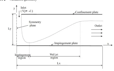
The schematic of the present investigation is shown as Figure 1. In the present investigation the water is considered as fluid. The 2D laminar incompressible fluid approach is adopted in this investigation. For the sake of simplicity, the present computational domain is considered as a single phase fluid approach. The block height (h) and width (w) are considered as constant and equal to 0.5.The jet width is set as 0.5 in order to have the hydraulic diameter (Dh) as the unity. The uniform velocity profile is
taken at the entrance of the jet. In the present simulation, the bottom wall is at higher temperature compared to top wall (or) confinement wall. The length of the physical model is taken as 20Dh in order to have fully developed flow at exit. The length of the domain in Y direction is considered as 2.5 and also it is a constant one. The aspect ratio is considered as 5 which is the ratio between length of the domain in Y direction (Ly) and jet width (W). A jet emerges from the slot nozzle and impinges on the block and reattaches on the bottom wall. The different Reynolds numbers (5, 10, 20, 50 and 100) are carried out in the investigations. The vortex (or) recirculation formed nearer to the block is called adjacent vortex. The vortex formed on the top wall is called primary vortex and the vortex formed on the bottom wall is called secondary vortex. The size and number of vortices are invariably dependent on the jet velocity.
Figure 1 Schematic diagram and boundary conditions of jet impingement
2.2 Assumptions
The density and viscosity of water are assumed as constant. The no slip boundary condition is adopted in the top and the bottom walls. The flow is assumed as two dimensional, laminar and incompressible. Body forces acting on the fluid are neglected, because at such low velocity, their effect on the flow regime is negligible. The jet width (W) is taken as 0.5 for all the cases, in order to have a hydraulic diameter as the unity (Dh = 1). Non-conjugate heat transfer is adopted i.e., the thickness of the bottom slab of the bottom wall in heat transfer is neglected, and the block surface as well as the impinging plate as a whole is assumed to be maintained at a constant temperature that is higher than that of the inlet jet and upper confinement plate.
2.3 Governing equations
The two-dimensional laminar incompressible fluids are represented in the following equations (David et al., 2012).
• Continuity equation: U V 0 X Y ∂ +∂ = ∂ ∂ (2.31) • X-momentum equation: 2 2 2 2 U U P 1 U U U V X Y X Re X Y ∂ ∂ ∂ ⎛∂ ∂ ⎞ ⎛ ⎞+ = − + + ⎜ ⎟ ⎜ ⎟ ∂ ∂ ∂ ∂ ∂ ⎝ ⎠ ⎝ ⎠ (2.32) • Y-momentum equation: 2 2 2 2 V V P 1 V V U V X Y Y Re X Y ∂ ∂ ∂ ⎛∂ ∂ ⎞ + = − + ⎜ + ⎟ ∂ ∂ ∂ ⎝∂ ∂ ⎠ (2.33) • Energy equation: 2 2 2 2 θ θ 1 θ θ U V X Y Re Pr X Y ∂ ∂ ⎛∂ ∂ ⎞ + = ⎜ + ⎟ ∂ ∂ ⎝∂ ∂ ⎠ (2.34)
The non-dimensional variables considered for this problem are, 2 x h y h in in in X L / D , Y L / D , U u / U , V v / U , P p / ρU= = = = =
(
h)
Re= ρuD / µ and Nu= −∂ ∂(
θ/ Y)
at Y=0 where f f c h c T T θ T T − =− is the non-dimensional temperature in the fluid region and
w c s h c T T θ T T − =
− is the non-dimensional temperature in the solid region.
The term θs is always 1 for the non-conjugate case, i.e., the effect of the slab thickness is neglected. Here the temperature of the wall is assumed as the temperature of the hot fluid (Tw = Th).
2.4 Commercial packages used and validation work
The fluid flow, impinging on the solid block, reattaches on the bottom wall and attains fully developed flow at exit condition.
The Gambit software (pre processor) is used to generate the mesh inside the computational domain. Since there are no sharp curvatures the quadrilateral mesh has been used for the entire computational domain. The Fluent (12.0) software is used to analyse the different types of flow situations. Tec plot (post processor) is used to visualise the flow for various Reynolds number and for the flow pattern at various place in computational domain.
Figure 2 Validation geometry
In order to prove the present algorithm the validation work has been done against Sivasamy et al.’s (2007) paper. The centres of primary vortex centre for different Reynolds number (100 to 500 with the step of 100) are produced by using the present algorithm and it is compared with the Sivasamy et al. (2007) result.
Figure 3 X-velocity contours and streamlines for aspect ratio 5 and Re = 100 (see online version for colours)
Table 1 compares the centre of primary vortex in x coordinate produced by present algorithm with the result of Sivasamy. Table 2 compares the centre of primary vortex in y coordinate produced by present algorithm with the result of Sivasamy.
Table 1 Centre for primary vortex in X-coordinate
S. no. Re X-coordinate (present result) X-coordinate (Sivasmy result)
1 100 1.90 1.90
2 200 3.12 3.07
3 300 4.08 4.05
4 400 4.86 4.84
5 500 5.43 5.42
Table 2 Centres for primary vortex in Y-coordinate
S. no. Re Y-coordinate (present result) Y-coordinate (Sivasmy result)
1 100 1.43 1.41
2 200 1.52 1.49
3 300 1.60 1.56
4 400 1.64 1.63
Table 1 and Table 2 show the present results which are in good agreement with Sivasamy results.
3 Results and discussions
3.1 Flow field investigation
In the present investigation the flow field is analysed for various Reynolds number like Re = 5, Re = 10, Re = 20, Re = 50 and Re = 100. From the flow field investigation it is found out that with the increase of Re the number of the vortices increase.
Figure 4 Stream line contour for different Re number, (a) = 5 (b) = 20 (c) = 50 (d) = 100 (e) = 150 (see online version for colours)
(a)
(b)
(c)
(d)
(e)
From Figure 4, it is predicted that when the Reynolds number increases the size of the vortices also increases. For low Reynolds number there is no formation of secondary vortex. The stream lines are parallel to each other which depicting the flow as a developed one at the exit. While increasing the Reynolds numbers the vortex centres are
also moving in downstream direction. After the water impinging on the solid block the water reattaches on a lower plate. Nearer to the block due to low pressure region the adjacent vortex is formed. The primary vortex is formed due to the entrainment effect and secondary vortex is formed due to increased frictional force and retarding the effect of primary vortex.
3.2 Horizontal velocity profile for various Reynolds numbers
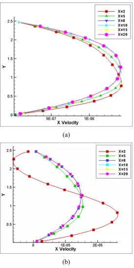
Figure 5 shows the horizontal velocity profile for various Reynolds numbers at various places in computational domain. The parabolic profile at X = 20 represents that the flow developing one at exit. The negative magnitude of velocity represents the vortex formation in the computational domain. For lower inertia force the flow attains fully developed condition at earlier stage and for higher inertia force the flow attains fully developed condition before the exit. The negative velocity represents in the confined wall represents formation of top wall vortex.
Figure 5 Horizontal velocity profile for various Re, (a) Re = 5 (b) Re = 50 (c) Re = 100 (see online version for colours)
(a)
Figure 5 Horizontal velocity profile for various Re, (a) Re = 5 (b) Re = 50 (c) Re = 100 (continued) (see online version for colours)
(c)
3.3 Effect of Reynolds number on vortex centre
Tables 3, 4 and 5 represent the vortex centre for adjacent, primary and secondary vortices. From the table it is noted that for the low Reynolds number there is only adjacent vortex. By increasing the Reynolds number only the primary and secondary vortices are formed. From the table it is concluded that the vortex centre are moving in downstream direction with the increase of Reynolds number.
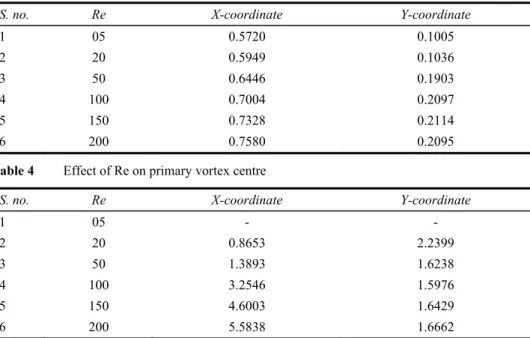
Table 3 Effect of Re on adjacent vortex centre
S. no. Re X-coordinate Y-coordinate
1 05 0.5720 0.1005 2 20 0.5949 0.1036 3 50 0.6446 0.1903 4 100 0.7004 0.2097 5 150 0.7328 0.2114 6 200 0.7580 0.2095
Table 4 Effect of Re on primary vortex centre
S. no. Re X-coordinate Y-coordinate
1 05 - - 2 20 0.8653 2.2399 3 50 1.3893 1.6238 4 100 3.2546 1.5976 5 150 4.6003 1.6429 6 200 5.5838 1.6662
Table 5 Effect of Re on secondary vortex centre
S. no. Re X-coordinate Y-coordinate
1 05 - - 2 20 - - 3 50 - - 4 100 7.5811 0.3088 5 150 8.6881 0.5724 6 200 10.4426 0.6951
From Tables 3, 4 and 5, it is concluded that there is a dominant change in primary vortex centre and secondary vortex centre as compared to adjacent vortex centres.
3.4 Effect of Re on reattachment lengths
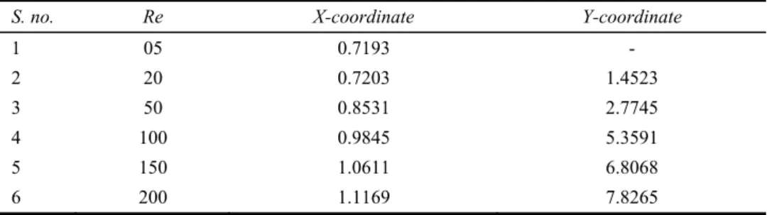
The most fluid impinges on a solid block which is called stagnation region and the fluid reattaches on the bottom wall which is called reattachment point. The distance between the stagnation point and reattachment point is called reattachment length (Xr1). When the Reynolds number increases from 5 to 20, there is a detachment of fluid. Some of the fluid gets separated and it reattaches on the top wall which is called reattachment length (Xr2). From Table 6, it is noted that the reattachment lengths (Xr1 and Xr2) are direct dependents on Reynolds number. The reattachment lengths increase with the increase of Reynolds number.
Table 6 Effect of Re on reattachment lengths (Xr1 and Xr2)
S. no. Re X-coordinate Y-coordinate
1 05 0.7193 - 2 20 0.7203 1.4523 3 50 0.8531 2.7745 4 100 0.9845 5.3591 5 150 1.0611 6.8068 6 200 1.1169 7.8265
3.5 Heat transfer investigation
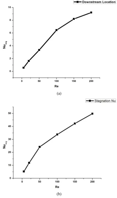
In the present investigation, the heat transfer is examined for the top of the block and downstream of the computational domain. It is predicted that the Nusselt number in the average Nu of top of the block surface i.e. impingement surface is higher compared to the average Nusselt number of the downstream location of the computational domain.
Figure 6 (a) Effect of Re on average Nusselt number in downstream location (b) Effect of Re on average Nusselt number in solid block location
(a)
(b)
From Figure 7, it is noted that there is a steep increase in heat transfer rate up to the Reynolds number of 100. Then there is a slowdown in heat transfer with further increase of Reynolds number. From the previous studies, it is predicted that the maximum Nusselt number occurs at the stagnation region i.e. on the block. Figure 7 reveals that the average Nusselt number at the stagnation point is higher than average Nusselt number of downstream location.
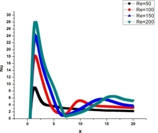
Figure 7 Local Nusselt number in downstream location (see online version for colours)
Figure 7 depicts the local Nusselt number distribution in downstream location for the various Reynolds number. For the Reynolds number of 50 there is a single peak and further increase of Reynolds number of 50 secondary peaks are prominently generated in the downstream location for each and every Reynolds number.
The location of secondary peak is shifting in downstream direction with the increase of Reynolds number. Secondary peak Nusselt number increases in a larger magnitude when the Reynolds number increases.
4 Conclusions
The flow field investigation and heat transfer investigation along the jet impingement on a solid block is presented. In case of flow filed investigation the vortex centers, reattachment lengths and vortex sizes are direct dependent on Reynolds number. In case of heat transfer investigation, the Nusselt number is higher in the stagnation region i.e. impingement region compared to downstream location of the computational domain.
References
Banooni, S., Hosseinalipour, S.M., Mujumdar, A.S., Taheran, E. and Mashaiekhi, M. (2008) ‘Impingement heat transfer effects on baking of flat bread,drying technology’, Drying Technology, Vol. 26, No. 7, pp.910–919.
David, S.C., Rajesh Kanna, P., Madhusudhana, G.R., Venkumar, P. and Mohammed, H.A. (2012) ‘Numerical investigation of heat transfer from a two-dimensional sudden expansion flow using nanofluids’, Numerical Heat Transfer, Part A, Vol. 61, pp.527–546.
Ersayın, E. and Selimefendigil, F. (2013) ‘Numerical investigation of impinging jets with nano fluids on a moving plate’, Mathematical and Computational Applications, Vol. 18, No. 3, pp.428–437.
Fenot, M., Dorignac, E. and Lalizel, G. (2015) ‘Heat transfer and flow structure of a multichannel impinging jet’, International Journal of Thermal Sciences, Vol. 90, pp.323–338.
Kohing, F.C. (1985) ‘Waterfall: water cooling systems’, Iron Steel Engineering, Vol. 6, No. 62, pp.30–36.
Manca, O., Mesolella, P., Nardini, S. and Ricci, D. (2011) ‘Numerical study of a confined slot impinging jet with nano fluids’, Nanoscale Research Letters, Vol. 6, p.188.
Rahimi-Esbo, M., Ranjbar, A.A., Ramiar, A. and Rahgoshay, M. (2012) ‘Numerical simulation of forced convection of nanofluid in a confined jet’, Heat Mass Transfer, Vol. 48, No. 12, pp.1995–2005.
Royne, A. and Dey, C.J. (2007) ‘Design of a jet impingement cooling device for densely packed PV cells underhigh concentration’, Solar Energy, Vol. 81, No. 8, pp.1014–1024.
Sivasamy, A., Selladurai, V. and Rajeshkanna, P. (2007) ‘Numerical simulation of two-dimensional laminar slot-jet impingement flows confined by a parallel wall’, International Journal for Numerical Methods in Fluids, Vol. 55, No. 10, pp.965–983.
Yousefi-Lafouraki, B., Ramiar, A. and Ranjbar, A.A. (2014) ‘Laminar forced convection of a confined slot impinging jet in a converging channel’, International Journal of Thermal Sciences, Vol. 77, pp.130–138.