A SPWM Full Bridge Inverter With Transformerless PV Grid Connected
Inverter
K.Ravikumar 1, K.E.Ch.Vidyasagar 2, Hidayathulla Patnam 3,Ponnaganti Siva Ramakrishna 4
1*Working as, Associative professor in the EEE Dept, Priyadarshini Institute of Technology & Science, Chintalapudi. 2*Working as, Assistant professor in the EEE Dept, Adama Science & Techonology university, Adama, Ethiopia.
3*Working as, Assistant professor in the EEE Dept, in MJR. 2* He is pursuing M.Tech in Electrical Power systems, in JNTU Kakinada.
ABSTRACT:
Unipolar sinusoidal pulse width modulation (SPWM) full-bridge inverter brings high-frequency common-mode voltage, which restricts its application in transformer less photovoltaic grid-connected inverters. In order to solve this problem, an optimized full-bridge structure with two additional switches and a capacitor divider is proposed in this paper, which guarantees that a freewheeling path is clamped to half input voltage in the freewheeling period. Sequentially, the high-frequency common mode voltage has been avoided in the Unipolar SPWM full-bridge inverter, and the output current flows through only three switches in the power processing period. In addition, a clamping branch makes the voltage stress of the added switches be equal to half input voltage. The operation and clamping modes are analyzed and the total losses of power device of several existing topologies and proposed topology are fairly calculated. Finally, the common mode performance of these topologies is compared by a universal prototype inverter rated at 1 KW.
Key words- SPWM, transformer less, unipolar.
I. INTRODUCTION:
Transformerless grid-connected inverters have a lot of advantages such as high efficiency, small size, light weight, low cost, etc. However, there is a galvanic connection between power grid and solar cell array. Depending on the inverter topology, this may cause fluctuation of the potential between the solar cell array and the ground, and these fluctuations may have a square wave at switching frequency.
When energized by a fluctuating potential, the stray capacitance to ground formed by the surface of the photovoltaic (PV) array may lead to the occurrence of ground currents. A person, connected to the ground and touching the PV array, may conduct the capacitive current to the ground, causing an electrical hazard. At the same time that the conducted interference and radiated interference will be brought
in by the ground current, the grid current harmonics and losses will also increase.
The Unipolar sinusoidal pulse width modulation (SPWM) full-bridge inverter has received extensive attentions, owing to its excellent differential mode characteristics such as higher dc voltage utilization, smaller current ripple in the filter inductor, and higher processing efficiency. However, the switching frequency time-varying common-mode voltage (whose amplitude is equal to a dc input voltage) is brought in. Therefore, a transformer (low frequency or high frequency) is needed to isolate the solar cell array from the grid in grid-connected applications, and at the same time, the high-frequency common- mode voltage endangers the insulation layer of the transformers, which increases its manufacturing cost. In order to remove this transformer from the unipolar SPWM full-bridge grid connected inverter, a lot of in-depth researches, where new freewheeling paths are constructed to separate the PV array from the grid in the freewheeling period, have been done ,. A pair of switches between the two midpoints of the bridge leg has been added in to construct a new freewheeling path in the freewheeling period.
half input voltage in the freewheeling period, but the output current flows through four switches in the power processing period, which increases the conduction losses.
Thin-film panels have a lot of advantages such as low cost and are suitable for building-integrated PV. However, its power density is lower than the conventional crystalline silicon module (which means that its conversion efficiency is lower). Thus, the stray capacitor of unit power module to the ground increases from 50–150 nF/kW for crystalline silicon module up to 1 μF/kW for thin-film module. Unfortunately, the transformerless grid-connected inverters make the ground current suppression become much more challenging in applications of thin-film panels. Considering both of the advantages and disadvantages of the existing topologies mentioned earlier, an optimized full-bridge structure has been proposed in this paper.
A controllable switch and a capacitor divider are added to form a bidirectional clamping branch which guarantees that the freewheeling path is clamped to half input
Voltage in the freewheeling period and the output current flows through only three switches in the power processing period, so that the conduction losses can be decreased effectively. In addition, the blocking voltage of added switches is only half of the input voltage, owing to the clamping structure, which is beneficial to further improve the efficiency. The total losses of power device for several existing topologies and the proposed topology have been calculated and compared in this paper.
Finally, the accuracy of the theoretical analysis and the validity of the clamping branch of the proposed topology are verified by a universal prototype inverter rated at 1 kW, and the common-mode performance of the optimized topology is also compared with those of several existing topologies. Because of its better ground current suppression performance and higher efficiency, this topology is suitable for high-power transformerless grid-connected inverters, particularly in thin-film solar cell applications.
II. PROPOSED SYSTEM
DESCRIPTION:
2. Objective:
The main goal of this project is to analyze and model transformerless PV inverter systems that are grid connected working under both voltage and current synchronization control. A comprehensive PV model cell will be implemented that takes into consideration the datasheet parameters provided by the manufacturer.
2.1 Background to the Research:
There are two main concepts that need to be introduced before proceeding with the research, these are: Solar Energy and Grid Connected PV Systems.
2.1.1 Solar Energy:
Energy is the most basic and essential of all resources. All the energy we use on earth comes from fission or fusion of atomic nuclei or from energy stored in the Earth. The problem with both fission and fusion is the dangerous side effect that radioactive manipulation might have. As a result most of the energy consumed in the world is strongly dependant on very limited non-renewable resources, particularly fossil fuel. As the world energy demand increases and resources begin to wane the search for alternative energy sources has become an important issue.
A lot of research has been done in the area of unlimited energy resources such as wind power generation and solar energy transformation. Of these the most effective and harmless energy is solar energy. The use of solar energy instead of fossil fuel combustions particular in areas of simple applications like low to medium water heating or battery charging can reduce the load of harmful emissions to the environment. This energy can be harvested by use of photovoltaic (PV) arrays. The photovoltaic generation systems can either be operated as isolated systems or be connected to the grid as a part of an integrated system, with other electrical generation, they form the distributed generation system. As renewable distributed generation, PV has some advantages if it is compared to other renewable energy generations. PV generation plant needs not a specific geographic or geo-morphological requirement such as on the wind and micro-small hydropower generation. In contrary, PV generation plant can be built in almost any area where the sun irradiation is available; allows the flexibility to determine the place of the plant according to its main allotment. In addition, the module-based production of PV2 plant components that enables one to build and adjust the size of PV plant from small capacity and then expand it to follow the demand growth is also one of advantages of this type of generation system. All of these facts make the PV modules an interesting choice for the development of electrical distributed generation systems.
2.1.2 Grid Connected PV Systems:
friendly energy resource than traditional ones. Nevertheless a PV system is still much more expensive than other methods of energy generation given the high manufacturing costs of PV panels.
One of the major advantages of PV technology is that it has no moving parts therefore the hardware is very robust; it has a long lifetime and low maintenance requirements and most importantly it is one solution that offers environmentally friendly power generation. Nowadays PV panels are present in everyday life: powering wrist watches, small calculators, supplying loads in remote sites and, and most importantly, they are connected to the public grid, generating the green power of the future.
According to the latest report of IEA PVPS on installed PV power, during 2010 there was a total of 35 GW capacity that could grow by 2050 to 3000 GW corresponding to an 11% of global electricity generation. Particularly in USA PV installation grew by 92% compared to 2009, for a total of approximately 900 MW. Preliminary market segment data show that commercial-scale projects constituted over 50 % of the market, residential systems about 25 %, and utility-scale projects the remainder. The top 7 states accounted for 76% of the market in 2010.
2.2 Aim of the Project:
The project has three main stages: The problem formulation the Objectives that are the specific goals of the research and finally the Thesis report.
2.2.1 Problem Formulation:
The efficiency of commercial PV panels is around 15-20%. Therefore, it is very important that the power produced by these panels is not wasted, by using inefficient power electronics systems. The efficiency and reliability of both single-phase PV inverter systems can be improved using transformerless topologies and maximum power point tracking methods. Simulation of modern electrical systems using power electronics has always been a challenge because of the nonlinear behavior of power switches, their connection to continuous sub-systems and the design of discrete-time control. Nowadays, more and more complex systems are studied for designing efficient control strategies, such as renewable energy conversion systems whole traction systems and so on. In these cases efficient simulations before practical control implantation are required. Furthermore very few systems address the three main problems in PV Inverter design. The researchers are either focused on simulating an accurate PV cell or in optimizing an MPPT model or designing a control for the inverter synchronization. Our research will approach the three problems first individually then integrate all the systems. It will also provide a friendly user interface that allows for multiple PV cell and modules simulation.
III. PHOTOVOLTAIC MODEL:
3.1 Solar cellsA solar cell (also called photovoltaic cell or photoelectric cell) is a solid state electrical device that converts the energy of light directly into electricity by the photovoltaic effect.
Assemblies of solar cells are used to make solar modules which are used to capture energy from sunlight. When multiple modules are assembled together (such as prior to installation on a pole-mounted tracker system), the resulting integrated group of modules all oriented in one plane is referred to in the solar industry as a solar panel. The electrical energy generated from solar modules referred to as solar power is an example of solar energy.
Photovoltaic’s is the field of technology and research related to the practical application of photovoltaic cells in producing electricity from light though it is often used specifically to refer to the generation of electricity from sunlight.
Cells are described as photovoltaic cells when the light source is not necessarily sunlight (lamplight, artificial light, etc.). These are used for detecting light or other electromagnetic radiation near the visible range for example infrared detectors or measurement of light intensity.
3.1.1 Basic operational principles:
The working principle of all today solar cells is essentially the same. It is based on the photovoltaic effect. In general, the photovoltaic effect means the generation of a potential difference at the junction of two different materials in response to visible or other radiation.
The basic processes behind the photovoltaic effect are 1. Generation of the charge carriers due to the absorption of photons in the materials that form a junction
2. Subsequent separation of the photo-generated charge carriers in the junction
3. Collection of the photo-generated charge carriers at the terminals of the junction.
Fig.1 operation of basic photovoltaic cell
electrons are knocked loose from the atoms in the semiconductor material. If electrical conductors are attached to the positive and negative sides, forming an electrical circuit the electrons can be captured in the form of an electric current that is electricity. This electricity can then be used to power a load such as a light or a tool.
A number of solar cells electrically connected to each other and mounted in a support structure or frame is called a photovoltaic module. Modules are designed to supply electricity at a certain voltage such as a common 12 volts system. The current produced is directly dependent on how much light strikes the module.
Fig.2 cell, module, array
Multiple modules can be wired together to form an array. In general the larger the area of a module or array the more electricity that will be produced. Photovoltaic modules and arrays produce direct-current (dc) electricity. They can be connected in both series and parallel electrical arrangements to produce any required voltage and current combination.
3.2 Applications
Solar cells are often electrically connected and encapsulated as a module. Photovoltaic modules often have a sheet of glass on the front (sun up) side allowing light to pass while protecting the semiconductor wafers from abrasion and impact due to wind-driven debris, rain, hail, etc. Solar cells are also usually connected in series in modules creating an additive voltage. Connecting cells in parallel will yield a higher current; however, very significant problems exist with parallel connections.
IV. PV INVERTERS:
A solar inverter or PV inverter is a critical component in a photovoltaic system. It converts the variable DC output of the solar panel into a utility frequency alternating current that can be fed into the commercial electrical grid or used by a local, off-grid electrical network. An inverter allows use of ordinary mains-operated appliances on a direct current system. Solar inverters have special functions adapted for use with PV arrays, including maximum power point tracking and anti-islanding protection.
The purpose of an inverter is to change Direct Current (DC) electricity into Alternating Current (AC) electricity. It also will increase the
voltage of the AC electricity to 120 Volts AC (if you're in the United States) or 240 Volts AC (if you're in most other parts of the world).
But why is a solar power inverter needed in the first place? Well, a solar inverter is needed because the electricity generated by your solar panels is DC electricity. In order to use the generated solar power with your electrical devices and household appliances, it needs to be converted to the standard voltage AC electricity for your region.
4.1 Solar Power Inverter Considerations:
Three factors homeowners should consider when evaluating inverters are
Power Quality
Power Rating
Efficiency
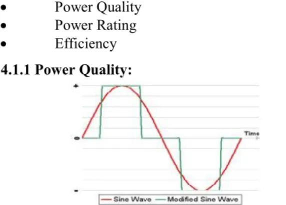
4.1.1 Power Quality:
Fig 3 Sine Wave Compared to Modified Sine Wave
The quality of the AC electricity generated by your inverter is important for household use. For most home solar power systems,you will want to use what's known as a pure sine wave inverter.These are also known as a true sine wave inverter.
This is considered "clean" power and is suitable for all household electrical applications such as computers, televisions, and microwaves. It is the same type of power provided by the utility companies. Some solar power inverters generate "dirty" power. This type of inverter converts the DC electricity into AC electricity that is in the form of a stepped square wave and is known as a modified sine wave inverter.
The AC electricity generated by this type of inverter can have a noticeable impact on your electrical equipment's performance. For example, audio speakers will buzz microwaves will take longer to heat food and television and computer monitors will display rolling lines.
4.1.2 Power Rating:
The amount of power the inverter can handle is known as its power rating. Two critical power ratings you will need to understand for your inverter are its continuous rating and its surge rating.
25% higher than the maximum power you will need to deliver to your household loads.
Household loads such as refrigerators and washing machines may require a short-term boost in power to get started. The amount of power can be 2 to 3 times the normal operating power, so make sure to check that your inverter's surge rating can handle that amount of power for a few seconds.
4.1.3Efficiency:
Inverter efficiency is another factor to consider. An inverter's efficiency indicates how much of the input DC power it converts into AC power. This will never be 100% because the inverter uses some of the input DC power itself generally around 10-25 W.
Fig.4 Typical Solar Inverter Efficiency Curve
The efficiency of an inverter depends on the power output level it is operating at. At different power levels it will be operating at different efficiencies. Inverters operate at maximum efficiency at a power level know as its peak efficiency point.
This is generally at around 20-30 percent of its maximum power rating. So if you have a 4000 W inverter its peak efficiency point will be between 800 and 1200 W.
An inverter's efficiency is shown in an efficiency curve. What you will see is that the inverter's efficiency will increase sharply until it reaches its peak efficiency point. It will then remain close to level decreasing slightly as it approaches its rated power output.
V. PWM SWITCHING TECHNIQUE:
The PWM switching can be divided into two switching scheme which are PWM with Bipolar voltage switching and PWM with Unipolar voltage switching
5.1 PWM with Bipolar Voltage Switching
The basic idea to produce PWM Bipolar voltage switching signal is shown in Figure 5. It comprises of a comparator used to compare between the reference voltage waveform Vr the triangular carrier signal VC and produces the bipolar switching signal. If this scheme is applied to the full bridge single phase inverter all the switch S1, S2, S3 and S4
are turned on and off at the same time. The output of leg A is equal and opposite to the output of leg B. The output voltage is determined by comparing the reference signal, Vr and the triangular carrier signal, VC Comparison between these two signals and the resulting output waveform are clearly illustrated in Figure 6.
Fig.5 Bipolar PWM generator
Fig.6 SPWM with Bipolar voltage switching
(a) Comparison between reference waveform and triangular waveform (b) Gating pulses for S1 and S4 (c) Gating pulses for S2 and S3 (d) Output waveform
5.2 PWM with Unipolar Voltage Switching:
Fig.7 Unipolar PWM generator
Fig.8 SPWM with Unipolar voltage switching
(a) Comparison between reference waveform and triangular waveform (b) Gating pulses for S1 and S4 (c) Gating pulses for S2 and S3 (d) Output waveform
5.3 Grid Connected Inverters:
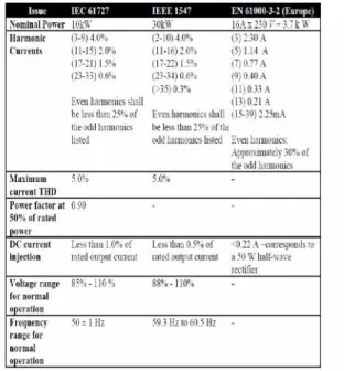
Grid connected Inverters need to be aware of the current standards and regulations which apply in the target country. The National Renewable Energy Laboratory published in 2003 the American National Standard ANSI/IEEE 1547. Additionally the International Electro-technical Commission also published the standard IEC 61727.
5.3.1 Voltage:
PV systems connected to the grid normally do not have any real influence on the grid voltage. Their voltage operation range are therefore more of a protection function that is used for detecting abnormal utility, rather than regulators. Such a typical voltage detection may be as defined in and shown in Table 1. Trip time refers to the time between the abnormal condition and the inverter ceasing to energize the utility line. The inverter will actually remain connected to the utility to allow the inverter to sense
utility electrical conditions for the reconnection process.
Table 1: Standards of Grid Connected Inverters 5.3.2 Voltage Control:
For the voltage control mode the transistors are controlled by using bipolar width modulation switching such that the inverter’s voltage follows the grid voltage. In a conventional PWM generation system a sinusoidal control signal is compared to a triangular carrier signal to generate the switching pattern. A different control method was implemented to emulate hardware DSP PWM generation. The inverter voltage is compared to a reference signal and the error is fed back through a proportional controller. The output of the controller is scaled and added to a feed forward loop with the final output of the new PWM duty .
Same as in a classic scenario the duty cycle is compared to a triangular wave to generate a switching signal to control the transistors gate .
5.3.3 Current Control:
5.4 Operation principle of the new converter: 5.4.1 Structure of New Converter:
In order to guarantee that the freewheeling path is clamped to half input voltage in the freewheeling period, two switches S1 and S2 and two capacitors Cdc1 and Cdc2 are introduced into the full-bridge inverter in this paper, as shown in Fig. 9(a). S1and S2 are the high-frequency switches at the positive terminal of the solar cell array. S3−S6 are switches of the full-bridge inverter. L1, L2, and C1 make up the filter connected to the grid. The freewheeling path through S3 and S5 (including their antiparallel diodes or body diodes), with S1, S4, and S6 off, guarantees that the potentials of points 1, 3, and 4 shown in Fig. 9(a) are equal (the potential of the freewheeling path is defined as this potential) and are clamped to the potential of point 2 by switch S2.
Fig.9 Optimized transformerless PV grid-connected inverter
(a) Proposed circuit structure with PV parasitic capacitors
(b) Gate drive signal with unity power factor.
5.4.2 Operation Principle Analysis
Grid-connected PV systems usually operate with unity power factor. The waveform of the gate drive signal for the proposed converter is shown in Fig. 10(b). In order to guarantee that the freewheeling path is completely clamped, S1 and S2 are switching complementarily, and then, S2, S3, and S5 must be on while S1, S4, and S6 are off in current zero-crossing. The main operation modes of the converter are shown in Fig.10, where power processing and freewheeling
modes in the positive half period and negative half period of the grid current are given, respectively.
In addition, the optimized topology with uni-polar SPWM described earlier can operate with power factors other than unity as shown in Fig. 9, and its operation analysis would be similar except that the grid voltage is reversed in phases B and D. Here, it is needed to point out that the drive signal is in phase with the grid current.
Similarly, an alternative topology has been proposed, shown in Fig.12, which has uniform operation principle as Fig. 9(a).
Fig.10 Equivalent circuits of working mode.
(a) Power processing mode and (b) freewheeling mode in the positive half period of the grid current. (c) Power processing mode and (d) freewheeling mode in the negative half period of the grid current.
Fig.11 Gate drive signal of the proposed inverter with power factors other than unity.
VI. SIMULATION CIRCUIT:
VII. SIMULATION RESULTS:
Fig.13 Single phase voltage controlled current output
Fig.14 Single phase voltage controlled harmonics
Fig.15 Single phase current controlled voltage output
Fig.16 Zoomed in current controlled output
VIII. CONCLUSION:
An optimized transformerless grid-connected PV inverter has been proposed in this paper, which has the following advantages.
1) The common-mode voltage is clamped to a constant level, so the ground current can be suppressed well.
2) The good differential-mode characteristic can be achieved like the unipolar SPWM full-bridge grid connected inverter with galvanic isolation, but with higher efficiency.
3) The blocking voltage of the added switches is only half of the input voltage.
These merits are verified and compared by a universal prototype rated at 240 V/50 Hz, 1 kW. It can be concluded that the proposed inverter is extremely suitable for high-power single phase grid-connected systems with thin-film solar cell.
IX. REFERENCES:
[1] European Photovoltaic Industry Association. (2011, May). Global market outlook for photovoltaics until 2015 [Online]. Available: http://www.epia.org [2] T. Kerekes, R. Teodorescu, P. Rodr´ıguez, G. V´azquez, and E. Aldabas, “A new high-efficiency single-phase transformerless PV inverter topology,” IEEE Trans. Ind. Electron., vol. 58, no. 1, pp. 184– 191, Jan. 2011.
[3] H. Xiao and S. Xie, “Transformerless split-inductor neutral point clamped three-level PV grid-connected inverter,” IEEE Trans. Power Electron., vol. 27, no. 4, pp. 1799–1808, Apr. 2012.
[4] H. Cha and T.-K. Vu, “Comparative analysis of low-pass output filter for single-phase grid-connected Photovoltaic inverter,” in Proc. 25th Annu. IEEE Appl. Power Electron. Conf. Expos., 2010, pp. 1659– 1665.
[5] M. Liserre, F. Blaabjerg, and S. Hansen, “Design and control of an LCLfilter-based three-phase active rectifier,” IEEE Trans. Ind. Appl., vol. 41,no. 5, pp. 1281–1291, Sep. 2005.
[6] O. Haillant, “Accelerated weathering testing principles to estimate the service life of organic PV modules,” Solar Energy Mater. Solar Cells,
[7] J. M. Fife, M. Scharf, S. G. Hummel, and R. W. Morris, “Field reliability analysis methods for photovoltaic inverters,” in Proc. 35th IEEE Photovoltaic Spec. Conf. (PVSC), Jun. 2010, pp. 2767–2772.
[8] R. Kadri, J.-P. Gaubert, and G. Champenois, “An improved maximum power point tracking for photovoltaic grid-connected inverter based on voltage-oriented control,” IEEE Trans. Ind. Electron., vol. 58, no. 1, pp. 66–75, Jan. 2011.
[9] E. Koutroulis and F. Blaabjerg, “Design optimization of grid-connected PV inverters,” in Proc. 26th Annu. IEEE Appl. Power Electron. Conf. Expos., Mar. 2011, pp. 691–698.
[10] P. Chaparala, E. Li, and S. Bhola, “Reliability qualification of photovoltaic smart panel electronics,” in Proc. 17th IEEE Int. Symp. Phys. Failure Anal. Integr. Circuits, Jul. 2010, pp. 1–4.
AUTHOR PROFILE:
1* K.RAVIKUMAR is Associative Professor of Electrical & Electronics Engineering department in Priyadarshini Institute of Technology & Science, Chintalapudi,from 2008 to still to date. I worked as Asst.Prof. In Chirala Enginering College. Earlier I Worked as lecturer in A.A.N.M &V.V.R.S.R polytechnic,Gudlavalleru. He obtained his B.Tech. Degree from P.V.R & J.C. college of Engineering,Chowdavaram and received his M.Tech from Nimra College of Engineering & Technology, Ibrahimpatnam. His research interest includes Power electronics & Electrical machines.
e-Mail:[email protected].
2* K.E.Ch.VIDYASAGARis Assistant Professor in Adama Science & Techonology university, Adama,Ethiopia. He worked as Asst.Prof. In Chirala Enginering College. He obtained his B.Tech. Degree from R.V.R&J.C.college of Engineering, Chowdavaram and received his M.Tech from Nimra College of Engineering & Technology, Ibrahimpatnam. His research interest includes
Power electronics & Electrical machines. e-Mail:[email protected]
3* HIDAYATHULLA PATNAM
was born in Andhra Pradesh, India, in 1986. He received the B.Tech. (electrical) degree from Jawaharlal Nehru Technological University, Hyderabad, India in 2008, the M.Tech
degree from Jawaharlal Nehru Technological University, Ananthapur, India in 2012. He joined the Cushman & Wakefield as a Technical Supervisor, Bangalore, India in 2008. In 2011 he joined MJR College of Engineering & Technology, Piler, India and currently working Assistant Professor in Department of Electrical and Electronics Engineering, in MJR. He is a fellow of The Institution of Engineers (India). His area of interest includes power quality improvement, power system security.
4* PONNAGANTI SIVA
RAMAKRISHNAwas born in