12Gb/s Intel® RAID Controllers
User Guide
DISCLAIMER
IINFORMATION IN THIS DOCUMENT IS PROVIDED IN CONNECTION WITH INTEL PRODUCTS. NO LICENSE, EXPRESS OR IMPLIED, BY ESTOPPEL OR OTHERWISE, TO ANY INTELLECTUAL
PROPERTY RIGHTS IS GRANTED BY THIS DOCUMENT. EXCEPT AS PROVIDED IN INTEL'S TERMS AND CONDITIONS OF SALE FOR SUCH PRODUCTS, INTEL ASSUMES NO LIABILITY WHATSOEVER AND INTEL DISCLAIMS ANY EXPRESS OR IMPLIED WARRANTY, RELATING TO SALE AND/OR USE OF INTEL PRODUCTS INCLUDING LIABILITY OR WARRANTIES RELATING TO FITNESS FOR A PARTICULAR PURPOSE, MERCHANTABILITY, OR INFRINGEMENT OF ANY PATENT, COPYRIGHT OR OTHER INTELLECTUAL PROPERTY RIGHT.
A "Mission Critical Application" is any application in which failure of the Intel Product could result, directly or indirectly, in personal injury or death. SHOULD YOU PURCHASE OR USE INTEL'S PRODUCTS FOR ANY SUCH MISSION CRITICAL APPLICATION, YOU SHALL INDEMNIFY AND HOLD INTEL AND ITS SUBSIDIARIES, SUBCONTRACTORS AND AFFILIATES, AND THE DIRECTORS, OFFICERS, AND EMPLOYEES OF EACH, HARMLESS AGAINST ALL CLAIMS COSTS, DAMAGES, AND EXPENSES AND REASONABLE ATTORNEYS' FEES ARISING OUT OF, DIRECTLY OR INDIRECTLY, ANY CLAIM OF PRODUCT LIABILITY, PERSONAL INJURY, OR DEATH ARISING IN ANY WAY OUT OF SUCH MISSION CRITICAL APPLICATION, WHETHER OR NOT INTEL OR ITS SUBCONTRACTOR WAS NEGLIGENT IN THE DESIGN, MANUFACTURE, OR WARNING OF THE INTEL PRODUCT OR ANY OF ITS PARTS.
Intel may make changes to specifications and product descriptions at any time, without notice. Designers must not rely on the absence or characteristics of any features or instructions marked "reserved" or "undefined". Intel reserves these for future definition and shall have no responsibility whatsoever for conflicts or incompatibilities arising from future changes to them. The information here is subject to change without notice. Do not finalize a design with this information.
The products described in this document may contain design defects or errors known as errata which may cause the product to deviate from published specifications. Current characterized errata are available on request.
Copies of documents which have an order number and are referenced in this document, or other Intel literature, may be obtained by calling 1-800-548-4725, or go to:
http://www.intel.com/design/literature.htm.
Intel warranties that this product will perform to its published specifications. However, all computer systems are inherently subject to unpredictable system behavior under various environmental and other conditions.
This product is not intended to be the sole source for any critical data and the user must maintain a verified backup. Failure to do so or to comply with other user notices in the product user guide and specification documents may result in loss of or access to data.
Preface
This is the primary user guide for the 12Gb/s Intel® RAID Controllers. It contains installation instructions and specifications.
Audience
The people who benefit from this document are:
•
12Gb/s Intel® RAID Controller usersOrganization
This document includes the following chapters and glossary:
•
Chapter 1 provides a general overview of the 12Gb/s Intel® RAID Controller.•
Chapter 2 provides the instructions on how to install the 12Gb/s Intel® RAID Controller.•
Chapter 3 describes the characteristics of the 12Gb/s Intel® RAID Controller.•
Chapter 4 provides a general overview and installation instructions of the Intel® RAID Maintenance Free Backup Unit AXXRMFBU4 and AXXRMFBU5.•
Glossary describes how to use the command-line-driven SAS-3 IntegratedRAID configuration utility (SAS3IRCU) to create and manage Integrated RAID volumes on Intel SAS-3 controllers.
Related Publication
This is the primary hardware guide for the 12Gb/s Intel® RAID Controllers. It contains installation instructions and specifications to aid in the configuration and use of this product.
Table of Contents
Preface ... iii
Audience ...iii
Organization ...iii
Related Publication ...iii
12Gb/s Intel® RAID Controller Overview ... 1
Overview ... 1
12Gb/s Intel® RAID Controllers with Support for RAID Maintenance Free Back Units . 2 SAS/SATA Standards and Communication Protocols ... 2
General Description ... 2
12Gb/s Intel® RAID Controller Detailed Descriptions ... 3
Intel® RAID Controller RS3WC080 ... 3
Intel® RAID Module RMS3HC080 ... 3
Intel® RAID Controller RS3DC040 and RS3DC080 ... 3
Intel® RAID Controller RS3MC044 ... 4
Intel® RAID Controller RS3SC008 ... 4
Intel® RAID Module RMS3CC080 ... 4
Configuration Scenarios ... 4
Benefits of the SAS Interface ... 5
PCI Express Architecture ... 6
Operating System Support ... 6
Summary of 12Gb/s Intel® RAID Controller Characteristics ... 7
SAS Features ... 8
SAS Array Limitations ... 9
SATA III Features ...10
PCI Express Performance ...10
Usability Features ...10
Flexibility Features ...11
Drive Roaming ...11
Drive Migration ...12
Hardware Specifications ...13
12Gb/s Intel® RAID Controller Hardware Installation ...15
Requirements ...15
Quick Installation ...15
Detailed Installation for 12Gb/s Intel® RAID Controllers ...16
Detailed Installation for 12Gb/s Intel® RAID Modules ...19
After Installing the RAID Controller ...21
SAS Device Cables and Connectors ...22 Connecting a RAID Controller with Internal Port Connectors by Cable to Internal Drives
23
12Gb/s Intel® RAID Controller Characteristics ... 25
12Gb/s Intel® RAID Controller Family ...25
Intel® RAID Controller RS3WC080 ...25
Intel® RAID Controller RS3DC040 and RS3DC080 ...27
Intel® RAID Controller RS3MC044 ...30
Intel® RAID Controller RS3SC008 ...33
Intel® RAID Module RMS3CC080 ...35
Intel® RAID Module RMS3HC080 ...37
12Gb/s Intel® RAID Controller Characteristics ...38
Technical Specifications ...38
RAID Controller Specifications ...39
Array Performance Features ...40
Fault Tolerance ...41
Electrical Characteristics ...41
Safety Characteristics ...46
Intel® RAID Maintenance Free Backup Unit AXXRMFBU4 and AXXRMFBU5 ... 47
About the Intel® RAID Maintenance Free Backup Unit AXXRMFBU ...47
Supported Intel® RAID Controllers and Modules ...48
Installing the Intel® RAID Maintenance Free Backup Unit ...48
Important Pre-installation Considerations ...48
Installing the Intel® RAID Maintenance Free Backup Unit AXXRMFBU4 Cache Off-load Module ...49
Installing the Intel® RAID Maintenance Free Backup Unit AXXRMFBU5 Cache Off-load Module ...50
Installing the Plastic RMFBU4 and RMFBU5 Super Capacitor Module to the Chassis 52 Connecting the RMFBU4 Cache Off-load Module to the Super Capacitor Module ...53
Connecting the RMFBU5 Cache Off-load Module to the Super Capacitor Module ...54
Monitoring the Intel® RAID Maintenance Free Backup Unit ...55
Monitoring the SuperCap with the Intel® RAID BIOS Configuration Utility ...55
Visual Indicators of the LEDs on the RMFBU4 and RMFBU5 Cache Off-load Module 57 RAID Maintenance Free Backup Unit Specifications ...58
MegaRAID CacheVault™ Technology ...58
RMFBU Specifications ...58
List of Figures
Figure 1. Example of an Intel SAS Direct-Connect Application ... 5
Figure 2. Example of an Intel SAS RAID Controller Configured with an LSISASx12 Expander 5 Figure 3. Example of the Intel® RAID Controller RS3DC080 Installation in a PCIe Slot ... 17
Figure 4. Install the Barrel Standoff... 19
Figure 5. Install the RAID Module ... 20
Figure 6. Internal SAS Cable for Connection to SAS Drives, SATA II Drives, or SATA III Drives... 22 Figure 7. SATA III Connectors... 22
Figure 8. SAS Plugs, SATA Plugs, and SAS Backplane Receptacle Connector... 23
Figure 9. Connecting the Intel® RAID Controller RS3DC080 to a Drive... 24
Figure 10. Card Layout for the Intel® RAID Controller RS3WC080 ... 26
Figure 11. Card Layout for the Intel® RAID Controller RS3DC080... 27
Figure 12. Card Layout for the Intel® RAID Controller RS3MC044... 31
Figure 13. Card Layout for the Intel® RAID Controller RS3SC008... 33
Figure 14. Card Layout for the Intel® RAID Module RMS3CC080 ... 36
List of Tables
Table 1. 12Gb/s Intel® RAID Controller Features ...7
Table 2. 12Gb/s Intel® RAID Controller Array Limitations ...9
Table 3. 12Gb/s Intel® RAID Controller Hardware Specifications ...13
Table 4. Jumpers and Connectors on the Intel® RAID Controller RS3WC080 ...26
Table 5. Jumpers and Connectors on the Intel® RAID Controller RS3DC080 ...28
Table 6. Jumpers and Connectors on the Intel® RAID Controller RS3MC044 ...31
Table 7. Jumpers and Connectors on the Intel® RAID Controller RS3SC008 ...34
Table 8. Jumpers and Connectors on the Intel® RAID Module RMS3CC080 ...36
Table 9. Jumpers and Connectors on the Intel® RAID Module RMS3HC080 ...37
Table 10. 12Gb/s Intel® RAID Controller Characteristics ...38
Table 11. RAID Controller Specifications ...39
Table 12. Array Performance Features ...40
Table 13. Fault Tolerance Features ...41
Table 14. Power Supply for the Intel® RAID Controller RS3WC080 ...41
Table 15. Power Supply for the Intel® RAID Controller RS3DC0x0 ...42
Table 16. Power Supply for the Intel® RAID Controller RS3MC044 ...44
Table 17. Power Supply for the Intel® RAID Controller RS3SC008 ...45
Table 18. RMFBU4 Specifications ...58
1
12Gb/s Intel® RAID Controller
Overview
This document is the primary reference and user’s guide for the Intel® RAID Controllers based on the 12Gb/s SAS/SATA RAID-on-a-chip (ROC) devices. This document contains complete installation instructions and specifications for these RAID controllers.
Overview
The 12Gb/s Intel® RAID Controllers are high-performance intelligent PCIe-to-SATA+SAS controllers with RAID control capability. The 12Gb/s Intel® RAID Controllers provide reliability, high-performance, and fault-tolerant drive subsystem management. They are an ideal RAID solution for the internal storage of workgroup, departmental, and enterprise systems.The 12Gb/s Intel® RAID Controllers offer a cost-effective way to implement RAID in a server.
SAS technology brings a wealth of options and flexibility with the use of SAS devices and SATA devices within the same storage infrastructure. However, SAS devices and SATA devices bring individual characteristics that make each one a more suitable choice depending on your storage needs. The 12Gb/s Intel® RAID Controller gives you the flexibility to combine these two similar technologies on the same controller, within the same enclosure, and in the same virtual drive.
Note: Carefully assess any decision to mix SAS drives and SATA drives within the same virtual drive. Although you can mix drives, the practice is strongly discouraged.
Intel offers a family of 12Gb/s Intel® RAID Controllers that address the needs for both internal and external solutions. The 12Gb/s Intel® RAID Controllers are based on the LSI first-to-market SAS IC technology and proven MegaRAID technology. As second-generation PCIe RAID controllers, these controllers address the growing demand for increased data throughput and scalability requirements across midrange and enterprise-class server platforms. These controllers provide these features:
•
12 Gb/s Serial Attached SCSI (SAS) performance•
6 Gb/s SATA III performance12Gb/s Intel® RAID Controllers with Support for RAID
Maintenance Free Back Units
The Intel® RAID Controllers RS3DC0x0, RS3SC008, RS3MC044, and RMS3CC080 support the RAID Maintenance Free Backup Unit that protects the integrity of the cached data on Intel® Integrated RAID Modules by offloading the data stored in the RAM cache to NAND flash during a power loss event. And it eliminates the need for lithium ion (Li-ion) batteries traditionally used to protect DRAM cache memory on RAID controllers.
SAS/SATA Standards and Communication Protocols
The 12Gb/s Intel® RAID Controllers support the ANSI Serial Attached SCSI standard, version 3.0. In addition, the controller supports the SATA III protocol defined by the Serial ATA specification, version 3.0. Supporting both the SAS interface and the SATA interface, the SAS controller is a versatile controller that provides the backbone of both server and high-end workstation environments. Each port on your RAID controller supports SAS devices, SATA devices, or both, by using the following protocols:
•
SAS Serial SCSI Protocol (SSP), which enables communication with other SAS devices•
SATA, which enables communication with other SATA devices•
Serial Management Protocol (SMP), which communicates topologymanagement information directly with an attached SAS expander device
•
Serial Tunneling Protocol (STP), which enables communication with SATAdevices through an attached expander
General Description
The 12Gb/s Intel® RAID Controllers bring 12.0 Gb/s Serial Attached SCSI and SATA III performance to host adapter, workstation, and server designs. The 12Gb/s Intel® RAID Controller RS3WC080 and Module RMS3HC080 are based on the LSISAS3008 PCIe RAID On-a-Chip (ROC) device. The following Intel® RAID Controllers are based on the LSISAS3108 PCIe RoC device:
•
RS3DC080•
RS3DC040•
RS3SC008•
RS3MC044•
RMS3CC080The controllers support internal storage devices and external storage devices, which allow you to use a system that supports enterprise-class SAS drives and desktop-class SATA III drives. Each 12Gb/s Intel® RAID Controller can connect to drives directly and can use expanders to connect to additional drives. Simplified cabling between devices is an additional benefit.
These devices are compliant with the Fusion-MPT™ architecture and provides a PCIe x8 interface. Each port on the 12Gb/s Intel® RAID Controllers supports SAS devices, SATA devices, or both, using SSP, SMP, STP, and SATA. The SSP
protocol enables the 12Gb/s Intel® RAID Controllers to communicate with other SAS devices. The SATA protocol enables the 12Gb/s Intel® RAID Controllers to communicate with SATA devices.
Note: All of these RAID controllers provide an x8 PCIe 3.0 interface.
12Gb/s Intel® RAID Controller Detailed
Descriptions
The 12Gb/s Intel® RAID Controllers are described in detail in the following subsections.
Intel® RAID Controller RS3WC080
The Intel® RAID Controller RS3WC080 is a PCIe 3.0 Low-Profile SAS Controller that controls eight internal SAS/SATA ports through two SFF-8643 mini-SAS HD-4i internal connectors.
Intel® RAID Module RMS3HC080
The Intel® RAID Module RMS3HC080 is a PCI-Express* (PCIe*) 3.0 RAID adapter whose PCIe* connector is a custom 80-pin connector capable of performance up to 8GT/s per lane. The Intel® RAID Module RMS3HC080 is based on the LSISAS3008 I/O controller, uses a 16-MB Flash memory device for storing the BIOS and firmware, and controls eight internal SAS/SATA ports through two SFF-8643 mini-SAS HD-4i internal connectors.
Intel® RAID Controller RS3DC040 and RS3DC080
•
The Intel® RAID Controller RS3DC040 is a PCIe 3.0 Low-Profile SAS Controller that controls four internal SAS/SATA ports through one SFF-8643 mini-SAS HD-4i internal connector.•
The Intel® RAID Controller RS3DC080 is a PCIe 3.0 Low-Profile SAS Controller that controls eight internal SAS/SATA ports through two SFF-8643 mini-SAS HD-4i internal connectors.Intel® RAID Controller RS3MC044
The Intel® RAID Controller RS3MC044 is a PCIe 3.0 Serial-Attached SCSI/SATA Disk Array Controller that controls four internal SAS/SATA ports through one SFF-8643 mini-SAS HD-4i internal connector and four external SAS/SATA ports through one SFF-8644 mini-SAS HD-4e external connector.
Intel® RAID Controller RS3SC008
The Intel® RAID Controller RS3SC008 is a PCIe 3.0 Serial-Attached SCSI/SATA Disk Array Controller that controls eight external SAS/SATA ports through two SFF-8644 mini-SAS HD-4e external connectors.
Intel® RAID Module RMS3CC080
The Intel® RAID Module RMS3CC080 is a PCI-Express* (PCIe*) 3.0 RAID adapter whose PCIe* connector is a custom 80-pin connector capable of performance up to 8GT/s per lane. The Intel® RAID Module RMS3CC080 is based on the LSISAS3108 ROC controller, uses 1GB of DDR3 1866MHz memory as cache, and controls eight internal SAS/SATA ports through two SFF-8643 mini-SAS HD-4i internal connectors.
Configuration Scenarios
You can use the 12Gb/s Intel® RAID Controllers in three main scenarios:
•
Low-end internal SATA configuration: In this configuration, use the RAID controller as a high-end SATA II or SATA III compatible controller that connects up to eight drives either directly or through a port expander. This configuration is mostly for low-end or entry servers. An out-of-band I2C bus provides enclosure management. Side bands of both types of internal SAS connectors support the SFF-8485 (SGPIO) interface.•
Midrange internal SAS configuration: This configuration is like an internal SATA configuration, but with high-end SAS drives. This configuration is more suitable for low-range to midrange servers.•
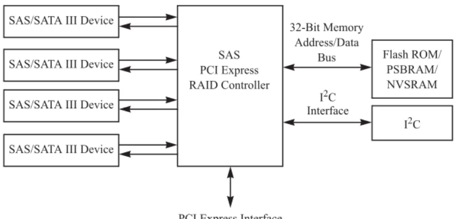
High-end external SAS/SATA configuration: This configuration is for external connectivity using SATA II drives, SATA III drives, SAS drives, or combinations of SATA and SAS drives. External enclosure management is supported through in-band, SCSI-enclosed storage. The configuration must support STP and SMP.The following figure shows a direct-connect configuration. The Inter-IC (I2C) interface communicates with peripherals. The external memory bus provides a 32-bit memory bus, parity checking, and chip select signals for pipelined synchronous burst static random access memory (PSBRAM), nonvolatile static random access memory (NVSRAM), and Flash ROM.
Figure 1. Example of an Intel SAS Direct-Connect Application
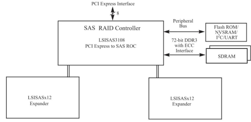
The following figure shows an example of a SAS RAID controller configured with an LSISASx12 expander that is connected to SAS drives, SATA III drives, or both.
Figure 2. Example of an Intel SAS RAID Controller Configured with an LSISASx12 Expander
Benefits of the SAS Interface
SAS is a serial, point-to-point, enterprise-level device interface that leverages the proven SCSI protocol set. SAS is a convergence of the advantages of SATA, SCSI, and Fibre Channel, and it is the future mainstay of the enterprise and high-end workstation storage markets. SAS offers a higher bandwidth per pin than parallel SCSI, and it improves signal and data integrity.
Flash ROM/ SAS
PCI Express RAID Controller SAS/SATA III Device
32-Bit Memory Address/Data
Bus
PSBRAM/
I2C SAS/SATA III Device
SAS/SATA III Device
SAS/SATA III Device
PCI Express Interface
NVSRAM I2C Interface LSISASx12 Flash ROM/ NVSRAM/ SRAM I2C/UART LSISASx12
PCI Express Interface 8 SRAM SRAM SDRAM Peripheral Bus 72-bit DDR3 with ECC Interface LSISAS3108
PCI Express to SAS ROC SAS RAID Controller
The SAS interface uses the proven SCSI command set to ensure reliable data transfers, while providing the connectivity and flexibility of point-to-point serial data transfers. The serial transmission of SCSI commands eliminates clock-skew challenges. The SAS interface provides improved performance, simplified cabling, smaller connectors, lower pin count, and lower power requirements when compared to parallel SCSI.
The SAS controllers leverage a common electrical and physical connection interface that is compatible with Serial ATA technology. The SAS protocols and the SATA III protocols use a thin, 7-wire connector instead of the 68-wire SCSI cable or 26-wire ATA cable. The SAS/SATA III connector and cable are easier to manipulate, allow connections to smaller devices, and do not inhibit airflow. The point-to-point SATA III architecture eliminates inherent difficulties created by the legacy ATA master-slave architecture, while maintaining compatibility with existing ATA firmware.
PCI Express Architecture
PCIe is a local bus system designed to increase data transfers without slowing down the central processing unit (CPU). You can install the 12Gb/s Intel® RAID Controllers in PCIe computer systems with a standard bracket type. With these controllers in your system, you can connect SAS devices and SATA devices over the bus.
Note: Some PCIe slots support PCIe graphics cards only; RAID controllers installed in these PCIe slots do not function.
PCIe goes beyond the PCI specification in that it is intended as a unifying I/O architecture for various systems: desktops, workstations, mobile devices, servers, communications, and embedded devices.
Operating System Support
The 12Gb/s Intel® RAID Controllers support the following operating systems:
•
Microsoft Windows 2003* R2 SP2, Windows Vista* SP2, Windows 7* ClientSP1, Windows 8*, Windows 2008* SP2, Windows 2008* R2 SP1, and Window Server 2012*
•
Red Hat* Linux•
SuSE* SLES•
Ubuntu* Linux•
VMware*•
Solaris*•
XenServer*Refer to the Intel SAS Device Driver Installation User Guide for more information about the drivers. To download the latest operating system drivers, go to
http://www.intel.com.
The 12Gb/s Intel® RAID Controllers use Fusion-MPT architecture for all major operating systems, thinner drivers, and better performance.
Summary of 12Gb/s Intel® RAID Controller
Characteristics
This section summarizes the features and benefits offered by the 12Gb/s Intel® RAID Controllers. It contains information on SAS features, SATA features, PCI performance, integration, usability, and flexibility.
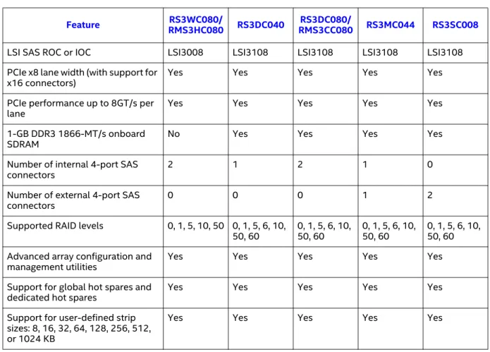
The 12Gb/s Intel® RAID Controllers have the following features.
Table 1. 12Gb/s Intel® RAID Controller Features
Feature RMS3HC080RS3WC080/ RS3DC040 RMS3CC080RS3DC080/ RS3MC044 RS3SC008
LSI SAS ROC or IOC LSI3008 LSI3108 LSI3108 LSI3108 LSI3108 PCIe x8 lane width (with support for
x16 connectors) Yes Yes Yes Yes Yes
PCIe performance up to 8GT/s per
lane Yes Yes Yes Yes Yes
1-GB DDR3 1866-MT/s onboard
SDRAM No Yes Yes Yes Yes
Number of internal 4-port SAS
connectors 2 1 2 1 0
Number of external 4-port SAS
connectors 0 0 0 1 2
Supported RAID levels 0, 1, 5, 10, 50 0, 1, 5, 6, 10,
50, 60 0, 1, 5, 6, 10, 50, 60 0, 1, 5, 6, 10, 50, 60 0, 1, 5, 6, 10, 50, 60 Advanced array configuration and
management utilities Yes Yes Yes Yes Yes
Support for global hot spares and
dedicated hot spares Yes Yes Yes Yes Yes
Support for user-defined strip sizes: 8, 16, 32, 64, 128, 256, 512, or 1024 KB
SAS Features
The 12Gb/s Intel® RAID Controllers support the following SAS features:
•
They provide four fully independent PHYs or eight fully independentPHYs, depending on the controller.
•
They support 12 Gb/s, 6Gb/s, and 3Gb/s SAS data transfers per PHY.•
They support SMP to communicate topology-management information.•
They support SSP to enable communication with other SAS devices.•
They support STP to enable communication with SATA devices throughan attached expander.
•
They provide a serial, point-to-point, enterprise-level storage interface.•
They simplify cabling between devices.•
They provide a scalable interface that supports up to 240 devices through the use of expanders.Advanced array configuration and management utilities offer these capabilities:
•
Online capacity expansion to add space to an existing drive or a new drive•
Online RAID level migration•
Drive migration•
Drive roaming•
No reboot necessary after expansion•
Load balancing•
Media scanYes Yes Yes Yes Yes
User-specified rebuild rate (specifying the percentage of system resources to use from 0 percent to 100 percent)
Yes Yes Yes Yes Yes
Nonvolatile random access memory (NVRAM) of 32 KB for storing RAID system configuration information; the MegaRAID SAS firmware is stored in flash ROM for easy upgrade.
Yes Yes Yes Yes Yes
Full MegaRAID Software Stack No Yes Yes Yes Yes
iMR Software Stack Yes No No No No
Note: The number of devices varies depending on the Intel® RAID Controller product. Check the Intel website, http://www.intel.com, for specific details about your product.
•
They support wide ports that consist of two, three, or four PHYs within a single quad port.•
They support narrow ports consisting of a single PHY.•
They transfer data by using SCSI information units.SAS Array Limitations
This section describes the array limitations of the 12Gb/s Intel® RAID Controllers. These limitations include the number of drives supported per controller, the maximum number of drives per controller, and the maximum number of virtual drives allowed per controller.
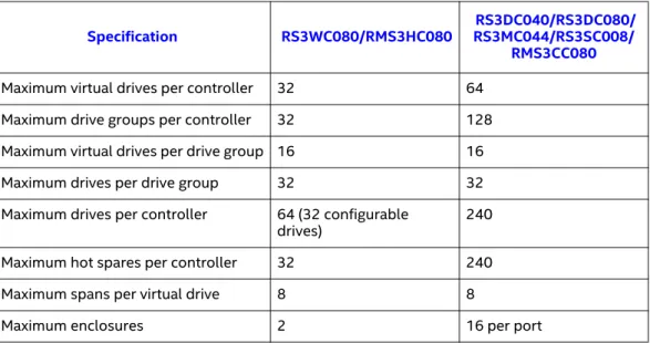
The following table lists the array limitations for the 12Gb/s Intel® RAID Controllers.
Table 2. 12Gb/s Intel® RAID Controller Array Limitations
The maximum numbers in the previous table depend on how many physical devices you have connected to the RAID controller. For example, the maximum number of drive groups is equal to the number of drives that are supported by the controller. Thus, for the Intel® RAID Controller RS3DC0x0, the maximum number of drive groups per controller is 240, which is based on the maximum number of physical devices that you can connect. In addition, the maximum number of hot spares per controller is equal to the maximum number of drives per controller.
Specification RS3WC080/RMS3HC080 RS3DC040/RS3DC080/RS3MC044/RS3SC008/
RMS3CC080
Maximum virtual drives per controller 32 64 Maximum drive groups per controller 32 128 Maximum virtual drives per drive group 16 16 Maximum drives per drive group 32 32 Maximum drives per controller 64 (32 configurable
drives) 240
Maximum hot spares per controller 32 240
Maximum spans per virtual drive 8 8
Although you can have up to 16 virtual drives per drive group, and up to 128 drive groups on most of the controllers, a limit of 64 virtual drives exists on those controllers.
These RAID controllers support 64-bit logical block addressing (LBA), which makes it possible to connect a large number of drives to the RAID controller, directly and through expanders. However, the actual number of drives that you can attach depends on the limits listed in this table rather than by actual RAID volume capacity.
SATA III Features
The following list describes the SATA III features of the RAID controllers:
•
They support SATA III data transfers of 6Gb/s for LSISAS3108-basedcontrollers.
•
They support STP data transfers of 3Gb/s.•
They provide a serial, point-to-point storage interface.•
They simplify cabling between devices.•
They eliminate the master-slave construction used in parallel ATA.•
They permit addressing of multiple SATA targets through an expander.•
They permit multiple initiators to address a single target (in a fail-overconfiguration) through an expander.
PCI Express Performance
The following list describes the PCIe performance features of the RAID controllers:
•
They provide a PCIe interface that does the following: — Supports a dedicated PCIe bus.— Supports x8 lane configuration.
— Supports transfer rates of up to 8GT/s per lane.
— Complies with the PCI Express specification, Revision 3.0, and the
Serial ATA specification, version 3.0.
•
They provide unequaled performance through the Fusion-MPT architecture.•
They provide high throughput and low CPU utilization to offload the host processor.Usability Features
•
They simplify cabling with point-to-point, serial architecture.•
They support smaller, thinner cables that do not restrict airflow.•
They provide drive spin-up sequencing control.•
They provide one LED signal for each PHY to indicate link activity (this is a fault LED only for controllers with internal port connectors).•
They provide an I2C interface for enclosure management.•
They support the internal SAS Sideband signal SFF-8485 (SGPIO) interface.Note: LED signals indicate an error condition or drive activity. The MegaRAID
controllers support different blink patterns for these LEDs, depending on the user configuration and storage enclosure. For information about the LED blink patterns, contact your storage enclosure manufacturer.
Flexibility Features
These features increase the flexibility of the RAID controllers:
•
They support a Flash ROM interface, a nonvolatile static RAM (NVSRAM) interface, and a pipelined synchronous burst SRAM (PSBRAM) interface.•
They offer a flexible programming interface to tune I/O performance.•
They permit mixed connections to SAS targets or SATA III targets.•
They leverage compatible connectors for SAS connections and SATA IIIconnections.
•
They permit grouping of up to four PHYs in a single quad port to form a wide port.•
They permit programming of the World Wide Name.Drive Roaming
Drive roaming occurs when the drives are changed to different ports on the same controller. When the drives are placed on different channels, the controller detects the RAID configuration from the configuration data on the drives.
Configuration data is saved in both the NVRAM on the RAID controller and on the drives attached to the controller. This action maintains the integrity of the data on each drive, even if the drives have changed their physical device ID.
Note: If you move a drive that is being rebuilt, the rebuild operation restarts; it does not resume from the stopping point.
1. Turn off the power to the server and all drives, enclosures, and system components. Disconnect the power cords from the system.
2. Open the host system by following the instructions in the host system technical documentation.
3. Move the drives to different positions on the backplane to change the targets.
4. Determine the SAS target requirements. 5. Perform a safety check.
a. Make sure that the drives are inserted correctly. b. Close the cabinet of the host system.
6. Reconnect the power cords to the system. 7. Turn on the power to the system.
The controller then detects the RAID configuration from the configuration data on the drives.
Drive Migration
Drive migration is the transfer of a set of drives in an existing configuration from one controller to another. The drives must remain on the same channel and must be reinstalled in the same order as in the original configuration. The controller to which you migrate the drives cannot have an existing configuration.
Note: Partial configurations, which include individual virtual drives, can be migrated.
Note: Drive roaming and drive migration cannot be supported at the same time.
Follow these steps to migrate drives:
1. Make sure that you clear the configuration on the system to which you migrate the drives to prevent a configuration data mismatch between the drives and the NVRAM.
Note: When you migrate drives, move only the drives that make up the virtual drive (not all of the drives in a drive group), so that you do not see an NVRAM mismatch error (providing a configuration is on the destination controller). The NVRAM mismatch error appears only if you move all of the drives to the other controller.
2. Turn off power to the server and all drives, enclosures, and system components. Disconnect the power cords from the systems.
3. Open the host system by following the instructions in the host system technical documentation.
4. Either remove the SAS cable connectors from the internal drives, or remove the shielded cables from the external drives that you want to migrate.
a. Make sure that pin 1 on the cable matches pin 1 on the connector. b. Make sure that the SAS cables conform to all SAS specifications. 5. Remove the drives from the first system, and insert them into the drive
bays on the second system.
6. Connect the SAS cables to the drives in the second system. 7. Determine the SAS target requirements.
8. Perform a safety check.
a. Make sure that all of the cables are attached correctly. b. Make sure that the RAID controller is installed correctly. c. Close the cabinet of the host system.
9. Reconnect the power cords to the system. 10. Turn on the power to the system.
The controller detects the RAID configuration from the configuration data on the drives.
Hardware Specifications
You can install the 12Gb/s Intel® RAID Controllers in a computer with a
motherboard that has a PCIe slot. The following table describes the hardware configuration features for the 12Gb/s Intel® RAID Controllers.
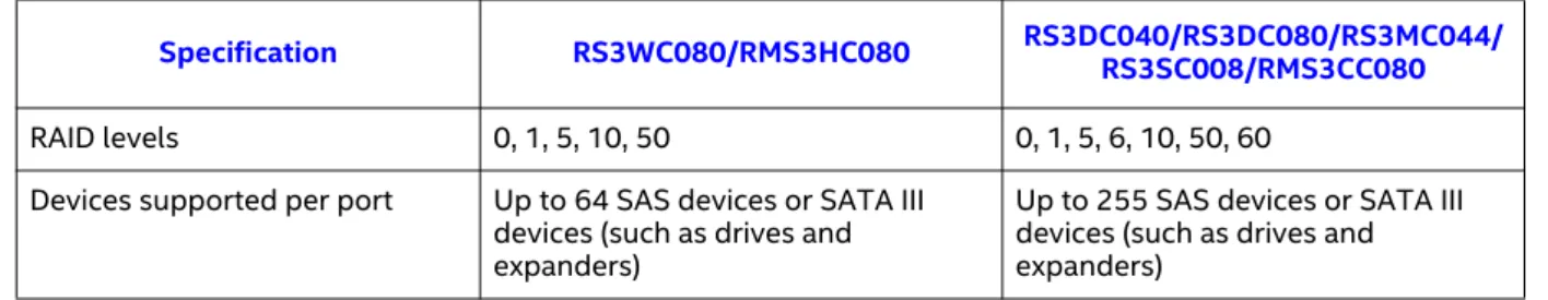
Table 3. 12Gb/s Intel® RAID Controller Hardware Specifications
Specification RS3WC080/RMS3HC080 RS3DC040/RS3DC080/RS3MC044/RS3SC008/RMS3CC080
RAID levels 0, 1, 5, 10, 50 0, 1, 5, 6, 10, 50, 60 Devices supported per port Up to 64 SAS devices or SATA III
devices (such as drives and expanders)
Up to 255 SAS devices or SATA III devices (such as drives and expanders)
Number of ports Eight ports through two SFF-8643
mini-SAS HD-4i connectors
•
RS3DC040 – Four ports through one SFF-8643 mini-SAS HD-4i connector•
RS3DC080 – Eight ports through two SFF-8643 mini-SAS HD-4i connectors•
RS3MC044 – Four external ports through one SFF-8644 mini-SAS HD-4e connector and four internal ports through one SFF-8643 mini-SAS HD-4i connector•
RS3SC080 – Eight external portsthrough two SFF-8644 mini-SAS HD-4e connectors
Data transfer rate Up to 12Gb/s per PHY Up to 12Gb/s per PHY
Bus PCIe 3.0 PCIe 3.0
PCIe form factor
•
RS3WC080: Standard PCIe•
RMS3HC080: Mezzanine port•
RS3DC040/RS3DC080/RS3MC044/ RS3SC008: Standard PCIe•
RMS3CC080: Mezzanine port Cache function Write-through, non-read-ahead,cache I/O, direct I/O Write-back, write-through, non-read-ahead, read-ahead, cache I/O, direct I/O
RAID Maintenance Free Backup
Unit (RMFBU) No support
•
RS3DC040/RS3DC080/RS3MC044/RS3SC080: RMFBU4•
RMS3CC080: RMFBU5Multiple virtual drives per
controller Up to 32 (this value is dependent on the firmware) Up to 64 (this value is dependent on the firmware)
Online capacity expansion Yes Yes
Dedicated and global hot spares Yes Yes
Hot-swap devices supported Yes Yes
Non-drive devices supported Yes Yes
Mixed-capacity drives supported Yes Yes Hardware exclusive OR (XOR)
assistance Yes Yes
Direct I/O Yes Yes
Architecture Fusion-MPT Fusion-MPT
2
12Gb/s Intel® RAID Controller
Hardware Installation
Requirements
The following items are required to install a 12Gb/s Intel® RAID Controller:
•
A 12Gb/s Intel® RAID Controller•
A host system with an available x8 PCIe 3.0 slotNote: These controllers also work in PCI Express first generation slots. The PCI Express software is backward compatible with previous revisions of the PCI bus and the PCI-X bus.
•
The necessary internal cables, external cables, or both•
SAS drives or SATA drivesNote: Make sure to use an uninterruptible power supply.
Quick Installation
The following steps quickly install your 12Gb/s Intel® RAID Controller. These steps are for experienced computer users or installers. Detailed Installation for 12Gb/s Intel® RAID Controllers or Detailed Installation for 12Gb/s Intel® RAID Modules contains the steps for all other users to follow.
1. Turn off the power to the system and all drives, enclosures, and system components, and disconnect the PC power cord.
2. Open the cabinet of the host system by following the instructions in the host system technical documentation.
3. Check the jumper settings to make sure that they are in the desired position. The jumpers are set at the factory, and you usually do not need to change them.
Note: See Chapter 3, 12Gb/s Intel® RAID Controller Characteristics, for detailed information about the jumpers and the connectors.
4. Install the 12Gb/s Intel® RAID Controller in the server, and connect SAS devices or SATA II devices to it. Make sure that the cables you use conform to all specifications.
5. Perform a safety check.
a. Make sure that all cables are attached correctly.
b. Make sure that the RAID controller is installed correctly. c. Close the cabinet of the host system.
6. Reconnect the power cords to the system. 7. Turn on the power to the system.
Make sure that the power is turned on to any external drives before the power is turned on to the host computer. If the computer is powered up before these devices, the devices might not be recognized.
Detailed Installation for 12Gb/s Intel® RAID
Controllers
This section provides detailed instructions on how to install your 12Gb/s Intel® RAID Controller.
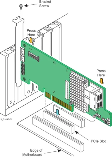
The figure in this section shows the installation of the Intel® RAID Controller RS3DC080 in a PCIe slot. You can install the Intel® RAID Controller RS3WC080, RS3DC040, RS3MC044, and RS3SC008 in the same way.
1. Unpack the 12Gb/s Intel® RAID Controller.
Unpack and remove your RAID controller. Inspect it for damage. If it appears damaged, contact your Intel Customer and Technical Support representative.
2. Turn off the power to the system.
Turn off the power to the computer, and disconnect the AC power cord. Remove the computer cover. Refer to the system documentation for instructions.
Caution: Before you install the controller, make sure that the computer is disconnected from the power and from any networks.
3. Review the RAID controller jumpers and connectors.
The jumpers are set at the factory, and you usually do not need to change them. See Chapter 3, 12Gb/s Intel® RAID Controller Characteristics, for diagrams of the 12Gb/s Intel® RAID Controllers that show their jumpers and connectors.
4. Install the RAID controller.
Select a PCIe slot, and align the controller’s PCIe bus connector to the slot, as shown in the following figure. Press down gently, but firmly, to make sure that the card is seated correctly in the slot. Secure the bracket to the computer chassis with the bracket screw.
Note: This RAID controller is a PCIe x8 card, and it can operate in x8 or x16 slots. Some PCIe slots, however, support only PCIe graphics cards; if a RAID controller is installed in one of these slots, the RAID controller will not function. Refer to the guide for your motherboard for information about the PCIe slot.
Figure 3. Example of the Intel® RAID Controller RS3DC080 Installation in a PCIe Slot Edge of Motherboard PCIe Slot Bracket Screw Press Here Press Here 3_01495-01
5. Configure and install the SAS devices, the SATA devices, or both in the host computer case.
Refer to the documentation for the devices for any pre-installation configuration requirements.
6. Connect the RAID controller to the devices.
Use SAS cables to connect SAS devices, SATA devices, or both to the 12Gb/s Intel® RAID Controller. See SAS Device Cables and Connectors for SAS cable and connector information. See Connecting a RAID Controller with Internal Port Connectors by Cable to Internal Drives for information about connecting the controller to the drives.
The maximum cable length is 10 meters (393.37 in.). You can connect one device per SAS PHY unless you use an expander.
System throughput problems can occur if the SAS cables are not the correct type. To minimize the potential for problems, use the following guidelines:
— Use cables no longer than 10 meters (393.37 in.). (Use shorter cables, if possible.)
— Use cables that meet the SAS specification. — Route the SAS cables carefully.
7. Turn on the power to the system.
Reinstall the computer cover, and reconnect the AC power cords. Turn on power to the host computer. Make sure that the power is turned on to the SAS devices, SATA devices, or both before or at the same time that the power is turned on to the host computer. If the computer is powered on before these devices, the devices might not be recognized.
During boot, a BIOS message appears. The firmware takes several seconds to initialize. The configuration utility prompt times out after several seconds. The second portion of the BIOS message shows the 12Gb/s Intel® RAID Controller number, firmware version, and cache SDRAM size. The numbering of the controllers follows the PCI slot scanning order used by the host motherboard.
8. Run the RAID BIOS Console Configuration Utility.
Run the RAID BIOS Console Configuration Utility to configure the drive groups and the virtual drives. When the message Press Ctrl+R for RAID BIOS Console appears on the screen, immediately press Ctrl+R to run the
utility.
9. Install the operating system driver.
The 12Gb/s Intel® RAID Controllers can operate under various operating systems. To operate under these operating systems, you must install the software drivers.
Detailed Installation for 12Gb/s Intel® RAID
Modules
This section provides detailed instructions on how to install your 12Gb/s Intel® RAID Module.
The figures in this section show the installation of the Intel® RAID Module RMS3HC080 in the Mezzanine port. You can install the Intel® RAID Module RMS3CC080 in the same way.
1. Unpack the 12Gb/s Intel® RAID Module.
Unpack and remove your RAID module. Inspect it for damage. If it appears damaged, contact your Intel Customer and Technical Support
representative.
2. Turn off the power to the system.
Turn off the power to the computer, and disconnect the AC power cord. Remove the computer cover. Refer to the system documentation for instructions.
Caution: Before you install the module, make sure that the computer is disconnected from the power and from any networks.
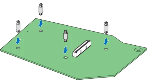
3. Install the barrel standoff.
a. Locate the matching SAS module connector on your server board. See your server board documentation.
b. Insert the barrel standoffs into the matching holes in the server board.
Figure 4. Install the Barrel Standoff
4. Review the RAID module jumpers and connectors.
The jumpers are set at the factory, and you usually do not need to change them. See Chapter 3, 12Gb/s Intel® RAID Controller Characteristics, for diagrams of the 12Gb/s Intel® RAID Module that show their jumpers and connectors.
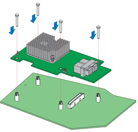
5. Install the RAID module.
a. Attach the RAID module to the matching server board connector and press the module card firmly to engage the barrel standoffs.
b. Press down gently but firmly to ensure that the card is properly seated in the connectors, and then insert the four pin standoffs into the barrel standoffs respectively.
Figure 5. Install the RAID Module
6. Configure and install the SAS devices, the SATA devices, or both in the host computer case. Refer to the documentation for the devices for any pre-installation configuration requirements.
7. Connect the RAID module to the devices.
Use SAS cables to connect SAS devices, SATA devices, or both to the 12Gb/s Intel® RAID Module. See SAS Device Cables and Connectors for SAS cable and connector information. See Connecting a RAID Controller with Internal Port Connectors by Cable to Internal Drives for information about connecting the module to the drives.
The maximum cable length is 10 meters (393.37 in.). You can connect one device per SAS PHY unless you use an expander.
System throughput problems can occur if the SAS cables are not the correct type. To minimize the potential for problems, use the following guidelines:
— Use cables no longer than 10 meters (393.37 in.). (Use shorter cables, if possible.)
— Use cables that meet the SAS specification. — Route the SAS cables carefully.
8. Turn on the power to the system.
Reinstall the computer cover, and reconnect the AC power cords. Turn on power to the host computer. Make sure that the power is turned on to the SAS devices, SATA devices, or both before or at the same time that the power is turned on to the host computer. If the computer is powered on before these devices, the devices might not be recognized.
During boot, a BIOS message appears. The firmware takes several seconds to initialize. The configuration utility prompt times out after several seconds. The second portion of the BIOS message shows the 12Gb/s Intel® RAID Module number, firmware version, and cache SDRAM size. The numbering of the modules follows the PCI slot scanning order used by the host motherboard.
9. Run the RAID BIOS Console Configuration Utility.
Run the RAID BIOS Console Configuration Utility to configure the drive groups and the virtual drives. When the message Press Ctrl+R for RAID BIOS Console appears on the screen, immediately press Ctrl+R to run the
utility.
After Installing the RAID Controller
After you install the 12Gb/s Intel® RAID Controller, you must configure the controller and install the operating system driver. The Intel® RAID Software User Guide instructs you on the configuration options and how to set them on your 12Gb/s Intel® RAID Controller. The Intel SAS Device Driver Installation User Guide provides detailed installation instructions for operating system drivers.
SAS Device Cables and Connectors
This section describes the cables and the connectors used on the 12Gb/s Intel® RAID Controllers and provides step-by-step instructions for connecting SAS drives, SATA drives, or both to the 12Gb/s Intel® RAID Controller. The SAS protocol and the SATA protocol use a thin, 7-wire connector instead of the 68-wire SCSI cable or the 40-wire ATA cable.
Note: Use only straight SAS cables, not crossover SAS cables.
The following figure shows the SAS cable that connects the internal connectors on a SAS RAID controller to SAS drives, SATA drives, or both.
Figure 6. Internal SAS Cable for Connection to SAS Drives, SATA II Drives, or SATA III Drives
The following figure shows the SATA III device plug connector that connects a SAS RAID controller with internal connectors to the host receptacle connector on a backplane. A SATA III connector consists of a signal connector and a power connector.
Figure 7. SATA III Connectors
Flash ROM/ SAS
PCI Express RAID Controller SAS/SATA III Device
32-Bit Memory Address/Data
Bus
PSBRAM/
I2C SAS/SATA III Device
SAS/SATA III Device
SAS/SATA III Device
PCI Express Interface
NVSRAM I2C Interface Device Plug Connector Host Receptacle Connector Serial ATA Signal Connector (pin 1) Serial ATA Power Connector (pin 1)
The following figure shows SAS connectors and SATA connectors on SAS drives and SATA drives, respectively. Cables connect internal connectors on the RAID controllers to connectors on SAS drives, SATA drives, or both. Both SAS drives and SATA drives can connect to SAS backplane receptacle connectors. The difference between the SAS connector and the SATA connector is the bridge between the SAS primary physical link and the power connector on the SAS controller, which the SATA connector does not have.
Note: SAS backplane connectors accept SAS drives or SATA drives, but SATA backplane connectors cannot accept SAS drives.
Figure 8. SAS Plugs, SATA Plugs, and SAS Backplane Receptacle Connector
The following subsection provides step-by-step instructions for connecting the 12Gb/s Intel® RAID Controllers to SAS drives and SATA drives, either directly or through an expander.
Connecting a RAID Controller with Internal Port Connectors
by Cable to Internal Drives
This section provides step-by-step instructions for connecting the SAS cable from the internal SAS port connectors on the RAID controller to internal SAS drives and SATA drives.
Follow these steps to connect your RAID controller with internal SAS port connectors directly to SAS drives or SATA drives.
Note: The Intel® RAID Controller RS3DC080 is shown as an example. You can connect the Intel® RAID Controller RS3DC040 in the same way.
Serial ATA SAS Primary Physical Link SAS Secondary Physical Link Power SATA II Physical Link Power
Serial Attached SCSI
SAS Backplane Receptacle Connector
Note: SATA backplane connectors do
not accept SAS drives. Power SAS Secondary Physical Link SATA II/SAS Primary Physical Link
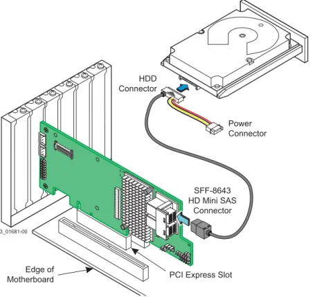
1. Insert the SFF-8643 internal mini-SAS HD-4i connector on the cable into a SFF-8643 internal mini-SAS HD-4i connector on the Intel® RAID Controller RS3DC080, as shown in the following figure.
2. Plug the HDD connector on the other end of the cable into the connector on the SAS drive or SATA drive.
3. If you have another drive, connect it to another plug on the internal cable. You can connect other devices if the cable has more connectors.
Figure 9. Connecting the Intel® RAID Controller RS3DC080 to a Drive
3_01681-00
Edge of
Motherboard PCI Express Slot
HDD Connector Power Connector SFF-8643 HD Mini SAS Connector
3
12Gb/s Intel® RAID Controller
Characteristics
12Gb/s Intel® RAID Controller Family
The 12Gb/s Intel® RAID Controllers are dual-PHY, SAS PCI Express RAID controllers and are used in a system with a PCI Express slot. PCI Express goes beyond the PCI specification in that it is intended as a unifying I/O architecture for various systems: desktops, workstations, mobile devices, servers,
communications, and embedded devices.
The following subsections provide figures and connector information for the 12Gb/s Intel® RAID Controllers.
Intel® RAID Controller RS3WC080
The Intel® RAID Controller RS3WC080 is a low-profile SAS+SATA RAID controller that controls eight internal SAS/SATA ports through two SFF-8643 internal mini-SAS HD-4i connectors.
Intel® RAID Controller RS3WC080 – Board Layout and Jumper and
Connector Information
This subsection provides the board layout, and the connector and jumper information for the Intel® RAID Controller RS3WC080. The following figure shows the jumpers and the connectors on the Intel® RAID Controller RS3WC080.
Figure 10. Card Layout for the Intel® RAID Controller RS3WC080
The following table describes the jumpers and the connectors on the Intel® RAID Controller RS3WC080.
Table 4. Jumpers and Connectors on the Intel® RAID Controller RS3WC080
Jumper/
Connector Type Description
EC1 Standard edge card connector PCIe* x8 board edge connector J1A SFF-8643 mini-SAS HD-4i internal
connector x4 SAS Port 0 through Port 3 J1B SFF-8643 mini-SAS HD-4i internal
connector x4 SAS Port 4 through Port 7
J2 10-pin header Complex programmable logic device (CPLD) header
Reserved for use.
J3 2-pin connector Modular RAID Key connector Reserved for use.
J4 4-pin connector On-board Serial Universal Asynchronous Receiver/Transmitter (UART) connector Reserved for use.
J5 16-pin header RISCwatch header
Reserved for use.
J6 2-pin header Test header
Reserved for use.
3_02070-00 EC1 J1A J5 J1B J3 J2 J4 J6
Intel® RAID Controller RS3DC040 and RS3DC080
The Intel® RAID Controller RS3DC040 is a low-profile SAS+SATA RAID controller that controls four internal SAS/SATA ports through one SFF-8643 internal mini-SAS HD-4i connectors.
The Intel® RAID Controller RS3DC080 is a low-profile SAS+SATA RAID controller that controls eight internal SAS/SATA ports through two SFF-8643 internal mini-SAS HD-4i connectors.
Intel® RAID Controller RS3DC080 – Board Layout and Jumper and
Connector Information
This subsection provides the board layout, and the connector and jumper information for the Intel® RAID Controller RS3DC0x0. The following figure shows the jumpers and the connectors on the Intel® RAID Controller RS3DC080.
Note: The Intel® RAID Controller RS3DC040 is the same as the Intel® RAID Controller RS3DC080 except that the J5A1 connector on the Intel® RAID Controller
RS3DC040 is a single internal port connector. The J5A1 connector on the Intel® RAID Controller RS3DC080 is a dual internal port connector.
Note: Pin 1 on the headers and connectors is highlighted in red in this figure.
Figure 11. Card Layout for the Intel® RAID Controller RS3DC080
3_01679-01 J1A2 J2B4 J4B1 J1A4 J1B1 J5B1 J6B1 J6B5 J6B4 J6B6 J6B3 J6B2 J1A3 J6B7 J5A1 J3L1
The following table describes the jumpers and the connectors on the Intel® RAID Controller RS3DC080.
Table 5. Jumpers and Connectors on the Intel® RAID Controller RS3DC080
Jumper/
Connector Type Description
J1A2 3-pin connector IPMI-style I2C connector for Ports 4 to 7. Supports SCSI Enclosure Services (SES) over I2C through an internal I2C backplane cable. J1A3 20-pin connector Local RAID Maintenance Free Backup Units
connector.
Connects the RMFBU directly to the RAID controller.
J1A4 3-pin connector IPMI-style I2C connector for Ports 0 to 3. Supports SES over I2C through an internal I2C backplane cable.
J1B1 2x8-pin header Ports 0 to 3 Ports 4 to 7
Individual PHY and drive fault indication header.
Connects to an LED that indicates whether a drive is in a fault condition. One LED exists per port. When lit, each LED indicates the corresponding drive has failed or is in the
Unconfigured-Bad state.
The LEDs function in a direct-attach
configuration (no SAS expanders exist). Direct attach is defined as a maximum of one drive connected directly to each port.
Note: The J5A1 connector on the Intel® RAID Controller RS3DC040 is a single internal port connector.
J2B4 Standard edge card connector The interface between the RAID controller and the host system.
Along with the PCIe interface, this connector provides power to the board and an I2C interface connected to the I2C bus for the Intelligent Platform Management Interface (IPMI).
J3L1 20-pin connector Remote RAID Maintenance Free Backup Units connector (on the backside of the controller). Connects the remote RMFBU to the RAID controller.
J4B1 70-pin connector Flash Module DDR3 Interface.
Connects the controller to a flash module. J5A1 Dual x4 SAS Port 0 through Port 7
internal connector Two SFF-8643 mini-SAS HD-4i internal connectors. Connects the controller by cable to SAS drives or SATA drives.
J5B1 2-pin connector Test header. Reserved for use.
J6B1 3-pin header Premium Feature Key header.
Enables support for selected advanced features, such as Recovery, CacheCade*, FastPath, and SafeStore* disk encryption. J6B2 2-pin connector Default Serial boot ROM (SBR) header.
Reserved for use.
J6B3 2-pin connector Global hard disk drive (HDD) activity LED header.
Connects to an LED that indicates activity on the drives connected to the controller.
J6B4 4-pin connector On-board Serial Universal Asynchronous Receiver/Transmitter (UART) connector. Reserved for use.
Jumper/
Intel® RAID Controller RS3MC044
The Intel® RAID Controller RS3MC044 is a low-profile SATA+SAS RAID controller that controls four internal SAS/SATA ports through one SFF-8643 internal mini-SAS HD-4i connector and four external SAS/SATA ports through one SFF-8644 mini-SAS HD-4e connector.
Intel® RAID Controller RS3MC044 – Board Layout and Jumper and
Connector Information
This subsection provides the board layout, and the connector and jumper information for the Intel® RAID Controller RS3MC044. The following figure shows the jumpers and the connectors on the controller.
Note: Pin 1 on the headers and connectors is highlighted in red in this figure.
J6B5 2-pin connector Global drive fault LED header.
Connects to an LED that indicates whether a drive is in a fault condition.
J6B6 6-pin connector Complex programmable logic device (CPLD) header.
Reserved for use.
J6B7 2-pin connector Cache write pending header.
Connector for an LED mounted on the system enclosure. The LED indicates that the data in the cache has yet to be written to the storage devices.
Jumper/
Figure 12. Card Layout for the Intel® RAID Controller RS3MC044
The following table describes the jumpers and the connectors on the Intel® RAID Controller RS3MC044.
Table 6. Jumpers and Connectors on the Intel® RAID Controller RS3MC044
Jumper/
Connector Type Description
J1A4 3-pin connector IPMI-style I2C connector for Ports 4 to 7.
Supports SCSI Enclosure Services (SES) over I2C through an internal I2C backplane cable.
J1A5 2-pin connector Default Serial boot ROM (SBR) header. Reserved for use.
J1A6 2-pin connector Global drive fault LED header.
Connects to an LED that indicates activity on the drives connected to the controller. J1A7 2-pin connector Cache write pending header.
Connector for an LED mounted on the system enclosure. The LED indicates that the data in the cache has yet to be written to the storage devices.
J1A8 5-pin connector CPLD header. Reserved for use.
3_02173-00 J1A11 J1B2 J2B4 J6B1 J1A6 J1A8 J1B1 J1A7 J1A5 J1A12 J1A4 J1A9 J2A1 J1A10
J1A9 4-pin connector On-board Serial Universal Asynchronous Receiver/Transmitter (UART) connector. Reserved for use.
J1A10 2x8-pin header Ports 0 to 3 Ports 4 to 7
Individual PHY and drive fault indication header.
Connects to an LED that indicates whether a drive is in a fault condition. One LED exists per port. When lit, each LED indicates the corresponding drive has failed or is in the
Unconfigured-Bad state.
The LEDs function in a direct-attach configuration (no SAS expanders exist). Direct attach is defined as a maximum of one drive connected directly to each port. J1A11 2-pin connector Global hard disk drive (HDD) activity LED
header.
Connects to an LED that indicates activity on the drives connected to the controller. J1A12 2-pin connector Test header.
Reserved for use.
J1B1 3-pin header Premium Feature Key header.
Enables support for selected advanced features, such as Recovery, CacheCade*, FastPath, and SafeStore* disk encryption. J1B2 x4 SAS Port 0 through Port 3
internal connector One SFF-8644 mini-SAS HD-4e external connector. Connects the controller by cable to an enclosure containing SAS drives or SATA drives.
J2A1 x4 SAS Port 0 through Port 3
external connector One SFF-8643 mini-SAS HD-4i internal connector. Connects the controller by cable to SAS drives or SATA drives.
J2B4 Standard edge card connector The interface between the RAID controller and the host system.
Along with the PCIe interface, this connector provides power to the board and an I2C interface connected to the I2C bus for the Intelligent Platform Management Interface (IPMI).
J2L1 20-pin connector Remote RAID Maintenance Free Backup Units connector (on the backside of the controller). Connects the remote RMFBU to the RAID controller.
Jumper/
Intel® RAID Controller RS3SC008
The Intel® RAID Controller RS3SC008 is a low-profile SATA+SAS RAID controller that controls eight external SAS/SATA ports through two SFF-8644 mini-SAS HD-4e connectors.
Intel® RAID Controller RS3SC008 – Board Layout and Jumper and
Connector Information
This subsection provides the board layout, and the connector and jumper information for the Intel® RAID Controller RS3SC008. The following figure shows the jumpers and the connectors on the controller.
Note: Pin 1 on the headers and connectors is highlighted in red in this figure.
Figure 13. Card Layout for the Intel® RAID Controller RS3SC008
The following table describes the jumpers and the connectors on the Intel® RAID Controller RS3SC008.
J4A1 80-pin connector Flash Module DDR3 Interface.
Connects the controller to a flash module. J6B1 20-pin connector Local RAID Maintenance Free Backup Units
connector.
Connects the RMFBU directly to the RAID controller.
Jumper/
Connector Type Description
3_02175-00 J1A11 J4A1 J2L1 J6B1 J1A5 J1B4 J1B3 J2B4 J1B2 J1B1 J1A8 J1A6 J1A12
Table 7. Jumpers and Connectors on the Intel® RAID Controller RS3SC008
Jumper/
Connector Type Description
J1A5 2-pin connector Default Serial boot ROM (SBR) header. Reserved for use.
J1A6 2-pin connector Global drive fault LED header.
Connects to an LED that indicates activity on the drives connected to the controller. J1A8 5-pin connector CPLD header.
Reserved for use.
J1A11 2-pin connector Global hard disk drive (HDD) activity LED header.
Connects to an LED that indicates activity on the drives connected to the controller. J1A12 x4 SAS Port 0 through Port 7
external connector Two SFF-8644 mini-SAS HD-4e external connectors. Connects the controller by cable to an enclosure containing SAS drives or SATA drives.
J1B1 3-pin header Premium Feature Key header.
Enables support for selected advanced features, such as Recovery, CacheCade*, FastPath, and SafeStore* disk encryption. J1B2 2-pin connector Cache write pending header.
Connector for an LED mounted on the system enclosure. The LED indicates that the data in the cache has yet to be written to the storage devices.
J1B3 2-pin connector Test header. Reserved for use.
J1B4 4-pin connector On-board Serial Universal Asynchronous Receiver/Transmitter (UART) connector. Reserved for use.
J2B4 Standard edge card connector The interface between the RAID controller and the host system.
Along with the PCIe interface, this connector provides power to the board and an I2C interface connected to the I2C bus for the Intelligent Platform Management Interface (IPMI).
Intel® RAID Module RMS3CC080
The Intel® RAID Module RMS3CC080 is an LSI* SAS3108 ROC based SATA+SAS RAID controller that controls four internal SAS/SATA ports through one SFF-8643 internal mini-SAS HD-4i connector.
The Intel® RAID Module RMS3CC080 is a PCI-Express* (PCIe*) 3.0 RAID adapter with a mezzanine port that is a custom 80-pin connector capable of
performance up to 8GT/s per lane.
Intel® RAID Module RMS3CC080 – Board Layout and Jumper and
Connector Information
This subsection provides the board layout, and the connector and jumper information for the Intel® RAID Module RMS3CC080. The following figure shows the jumpers and the connectors on the Intel® RAID Module RMS3CC080.
J2L1 20-pin connector Remote RAID Maintenance Free Backup Units connector (on the backside of the controller). Connects the remote RMFBU to the RAID controller.
J4A1 80-pin connector Flash Module DDR3 Interface.
Connects the controller to a flash module. J6B1 20-pin connector Local RAID Maintenance Free Backup Units
connector.
Connects the RMFBU directly to the RAID controller.
Jumper/
Figure 14. Card Layout for the Intel® RAID Module RMS3CC080
The following table describes the jumpers and the connectors on the Intel® RAID Module RMS3CC080.
Table 8. Jumpers and Connectors on the Intel® RAID Module RMS3CC080
Jumper/
Connector Type Description
J1 Mezzanine connector (on the
backside of the module) The PCIe* interface to the host system that is implemented with a board-to-board Mezzanine connector.
JT2 Dual x4 SAS Port 0 through Port 7
internal connector Two SFF-8643 mini-SAS HD-4i internal connectors. Connects the controller by cable to SAS drives or SATA drives.
JT3 Cache off-load connector Remote RAID Maintenance Free Backup Unit connector (on the backside of the controller). Connects the remote RMFBU to the RAID controller.
JT4 4-pin connector On-board Serial Universal Asynchronous Receiver/Transmitter (UART) connector. JT5 3-pin header Premium Feature Key header.
Enables support for selected advanced features, such as Recovery, CacheCade*, FastPath, and SafeStore* disk encryption.
AF006553
JT4
JT5
JT3
JT2
LSI SAS 3108
J1
Intel® RAID Module RMS3HC080
The Intel® RAID Module RMS3HC080 is an LSI* SAS3008 ROC based SATA+SAS RAID controller that controls four internal SAS/SATA ports through one SFF-8643 internal mini-SAS HD-4i connector.
The Intel® RAID Module RMS3HC080 is a PCI-Express* (PCIe*) 3.0 RAID adapter with a mezzanine port that is a custom 80-pin connector capable of
performance up to 8GT/s per lane.
Intel® RAID Module RMS3HC080 – Board Layout and Jumper and
Connector Information
This subsection provides the board layout, and the connector and jumper information for the Intel® RAID Module RMS3HC080. The following figure shows the jumpers and the connectors on the Intel® RAID Module RMS3HC080.
Figure 15. Card Layout for the Intel® RAID Module RMS3HC080
Table 9. Jumpers and Connectors on the Intel® RAID Module RMS3HC080
Jumper/
Connector Type Description
J1 2-pin connector Test Header.
Reserved for use.
J4 4-pin connector On-board Serial Universal Asynchronous Receiver/Transmitter (UART) connector.
AF006529
J1
LSI SAS 3008
J4
J5
J6
12Gb/s Intel® RAID Controller Characteristics
The following table shows the general characteristics for all 12Gb/s Intel® RAID Controllers.
Table 10. 12Gb/s Intel® RAID Controller Characteristics
A. For boot code and firmware. B. For BIOS configuration storage.
Each 12Gb/s Intel® RAID Controller ensures data integrity by intelligently validating the compatibility of the SAS domain. The 12Gb/s Intel® RAID Controllers use Fusion-MPT architecture, which allows for thinner drivers and better performance.
Technical Specifications
The design and implementation of the 12Gb/s Intel® RAID Controllers minimize electromagnetic emissions, susceptibility to radio frequency energy, and the effects of electrostatic discharge. The 12Gb/s Intel® RAID Controllers show the following marks and certifications:
•
CE mark•
C-Tick mark•
FCC Self-Certification logoJ5 Dual x4 SAS Port 0 through Port 7
internal connector Two SFF-8643 mini-SAS HD-4i internal connectors. Connects the controller by cable to SAS drives or SATA drives.
J6 Mezzanine connector (on the
backside of the module) The PCIe* interface to the host system that is implemented with a board-to-board Mezzanine connector.
Jumper/
Connector Type Description
Flash
ROM A EEPROM Serial B Data Transfer Rate SCSI Feature TerminationSCSI
Yes Yes Up to 12Gb/s per port for SAS and
up to 6Gb/s per port for SATA III Plug-and-PlayScatter/Gather Activity LED