Halogen Free
Value Added
ATA Disk Module
Ⅲ
Specification for Mini ADM (44P/90D)
Apr 26, 2011
Version 1.3
Apacer Technology Inc.
Features:
Standard ATA/IDE bus interface
– ATA command set compatible – ATA operating mode supports up to:
PIO Mode-4
Multiword DMA Mode-2 Ultra DMA Mode-4
Connector type
– 44-pin female connector
Low power consumption (typical)
– Supply voltage: 3.3V & 5V
– Active mode: 85mA/95mA (3.3V/5V) – Sleep mode: 500µA /600µA (3.3V/5V)
Performance
– Sustained read: Up to 35 MB/sec – Sustained write:
Standard: Up to 10 MB/sec High Speed: Up to 10 MB/sec
Capacity – Standard: 128, 256, 512 MB 1, 2, 16 GB – High Speed: 256, 512 MB 1, 2, 4, 8 GB
NAND Flash Type: SLC
Temperature ranges – Operation: Standard: 0°C to 70°C ET*: -40°C to 85°C – Storage: -40°C to 100°C Flash management
– Intelligent endurance design
Advanced wear-leveling algorithms S.M.A.R.T.
Built-in hardware ECC Enhanced data integrity
– Intelligent power failure recovery – Enhanced security level
Secure protection zone ATA Secure Erase
Halogen Free
Table of Contents
1.GENERAL DESCRIPTION ... 3
1.1PERFORMANCE-OPTIMIZED CONTROLLER... 3
1.1.1 Power Management Unit (PMU)... 3
1.1.2 SRAM Buffer ... 3
2. FUNCTIONAL BLOCK ... 4
3. PIN ASSIGNMENTS ... 5
4. CAPACITY SPECIFICATION ... 6
4.1PERFORMANCE SPECIFICATION... 6 4.2ENVIRONMENTAL SPECIFICATION... 75. FLASH MANAGEMENT ... 8
5.1INTELLIGENT ENDURANCE DESIGN... 8
5.1.1 Advanced wear-leveling algorithms ... 8
5.1.2 S.M.A.R.T. ... 8
5.1.3 Built-in hardware ECC ... 8
5.1.4 Enhanced data integrity ... 8
5.2INTELLIGENT POWER FAILURE RECOVERY... 9
5.3ENHANCED SECURITY LEVEL... 9
5.3.1 Secure protection zone ... 9
5.3.2 ATA Secure Erase ... 9
6. SOFTWARE INTERFACE ... 10
6.1COMMAND SET... 10
7. ELECTRICAL SPECIFICATION ... 12
8. PHYSICAL CHARACTERISTICS ... 13
8.1DIMENSION –MINI ADM... 13
8.1.1 44 pin/90 degree w/ jumper ... 13
8.1.2 44 pin/90 degree w/o jumper ... 14
9. PRODUCT ORDERING INFORMATION ... 15
9.1PRODUCT CODE DESIGNATIONS... 15
1. General Description
Apacer’s ATA-Disk Module (ADM) is a high-performance, embedded flash drive designed to replace the conventional IDE hard disk drive. The ADMs can be plugged into a standard IDE connector commonly found in desktops, IT-STB, industrial PCs and thin client systems. Apacer’s ADM SSD has a built-in microcontroller with file management firmware that communicates with the ATA standard interfaces. No additional or proprietary host software is required.
Well suited for embedded flash storage applications by offering new and expanded functionalities as well as more cost-effective designs, better performance and increased reliability, ADM is designed to work at either 5 or 3.3 Volts, supports the standard ATA/IDE protocol for up to PIO Mode-4, Multiword DMA Mode-2 and Ultra DMA Mode-4 interfaces, and uses the standard ATA driver complying with all major operating systems such as Microsoft’s Windows series, Apple’s Mac OS family, and Unix variants.
Featuring technologies as Advanced Wear-leveling algorithms, S.M.A.R.T, Enhanced Data Integrity, Intelligent Power Failure Recovery, Secure Protection Zone and ATA Secure Erase, Apacer’s ADM assures users of a versatile device on data storage.
1.1 Performance-Optimized Controller
The kernel of an ATA-Disk Module is the ATA controller, which translates standard ATA signals into the data and controls of the flash media. This proprietary ATA controller is specifically designed to attain high data throughput from the host to the flash.
1.1.1 Power Management Unit (PMU)
The power management unit (PMU) controls the power consumption of the ATA-Disk Module. It reduces the power consumption of the ATA-Disk Module Controller by putting circuitry not in operation into sleep mode. The PMU has zero wake-up latency.
1.1.2 SRAM Buffer
The ATA-Disk Module Controller performs as an SRAM buffer to optimize the host’s data transfer to and from the flash media.
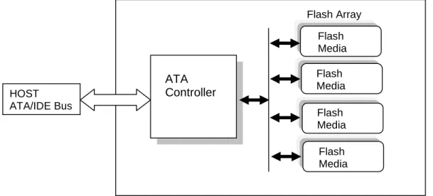
2. Functional Block
The ATA-Disk Module (ADM) includes the ATA controller and flash media, as well as the ATA standard interface. Figure 2-1 shows the functional block diagram.
Figure 2-1: Functional block diagram
ATA
Controller
Flash Media Flash Media Flash Media Flash Media Flash Array HOST ATA/IDE Bus3. Pin Assignments
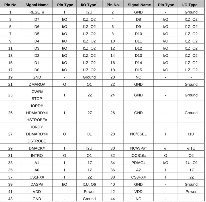
Table 3-1 lists the pin assignments with respective signal names for the 44-pin configuration. A “#” suffix indicates the active low signal. The pin type can be input, output or input/output.
Table 3-1: Pin assignments for the 44-pin configuration
Pin No. Signal Name Pin Type I/O Type1 Pin No. Signal Name Pin Type I/O Type
1 RESET# I I2U 2 GND - Ground 3 D7 I/O I1Z, O2 4 D8 I/O I1Z, O2 5 D6 I/O I1Z, O2 6 D9 I/O I1Z, O2 7 D5 I/O I1Z, O2 8 D10 I/O I1Z, O2 9 D4 I/O I1Z, O2 10 D11 I/O I1Z, O2 11 D3 I/O I1Z, O2 12 D12 I/O I1Z, O2 13 D2 I/O I1Z, O2 14 D13 I/O I1Z, O2 15 D1 I/O I1Z, O2 16 D14 I/O I1Z, O2 17 D0 I/O I1Z, O2 18 D15 I/O I1Z, O2 19 GND - Ground 20 NC - - 21 DMARQ# O O1 22 GND Ground 23 IOWR# STOP I I2Z 24 GND - Ground 25 IORD# HDMARDY# HSTROBE# I I2Z 26 GND - Ground 27 IORDY DDMARDY# DSTROBE O O1 28 NC/CSEL I I1U
29 DMACK# I I2U 30 NC/WP#1 -/I -/I1U 31 INTRQ O O1 32 IOCS16# O O2 33 A1 I I1Z 34 PDIAG# I/O I1U, O1 35 A0 I I1Z 36 A2 I I1Z 37 CS1FX# I I2Z 38 CS3FX# I I2Z 39 DASP# I/O I1U, O6 40 GND - Ground 41 VDD - Power 42 VDD - Power 43 GND - Ground 44 NC - -
1. Pin 30 is selectable as NC or WP# through a zero ohm resistor jumper. Default is NC. Note that pin 30 is a GND pin on standard
4. Capacity Specification
Capacity specification of the ATA-Disk Module (ADM) product family is available as shown in Table 4-1. It lists the specific capacity and the default numbers of heads, sectors and cylinders for each product line.
Table 4-1: Capacity specifications
Capacity Total bytes* Cylinders Heads Sectors Max LBA
128 MB 128,057,344 977 8 32 250,112 256 MB 256,901,120 980 16 32 501,760 512 MB 512,483,328 993 16 63 1,000,944 1 GB 1,024,966,656 1986 16 63 2,001,888 2 GB 2,048,385,024 3969 16 63 4,000,752 4 GB 4,096,253,952 7937 16 63 8,000,496 8 GB 8,001,552,384 15504 16 63 15,628,032 16 GB 16,001,040,384 16383** 16 63 31,252,032
*Display of total bytes varies from file systems.
**Cylinders, heads or sectors are not applicable for these capacities. Only LBA addressing applies
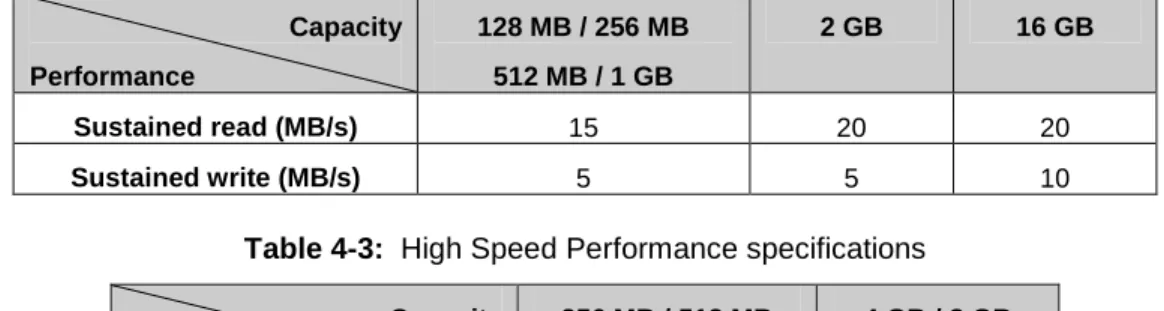
4.1 Performance Specification
Performances of the ATA-Flash Disk are listed in Table 4-2 and Table 4-3.
Table 4-2: Standard Performance specifications Capacity Performance 128 MB / 256 MB 512 MB / 1 GB 2 GB 16 GB Sustained read (MB/s) 15 20 20 Sustained write (MB/s) 5 5 10
Table 4-3: High Speed Performance specifications Capacity Performance 256 MB / 512 MB 1GB / 2 GB 4 GB / 8 GB Sustained read (MB/s) 25 35 Sustained write (MB/s) 7 10
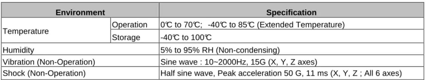
4.2 Environmental Specification
Environmental specification of the ATA-Disk Module (ADM) product family follows the MIL-STD-810F standard which is shown in Table 4-4.
Table 4-4: Environmental specifications Environment Specification
Operation 0°C to 70°C; -40°C to 85°C (Extended Temperature) Temperature
Storage -40°C to 100°C
Humidity 5% to 95% RH (Non-condensing)
Vibration (Non-Operation) Sine wave : 10~2000Hz, 15G (X, Y, Z axes)
5. Flash Management
5.1 Intelligent Endurance Design
5.1.1 Advanced wear-leveling algorithms
The NAND flash devices are limited by a certain number of write cycles. When using a file system, frequent file table updates is mandatory. If some area on the flash wears out faster than others, it would significantly reduce the lifetime of the whole device, even if the erase counts of others are far from the write cycle limit. Thus, if the write cycles can be distributed evenly across the media, the lifetime of the media can be prolonged significantly. The scheme is achieved both via buffer management and Apacer-specific advanced wear leveling to ensure that the lifetime of the flash media can be increased, and the disk access performance is optimized as well.
5.1.2 S.M.A.R.T.
S.M.A.R.T. is an acronym for Self-Monitoring, Analysis and Reporting Technology, an open standard allowing disk drives to automatically monitor their own health and report potential problems. It protects the user from unscheduled downtime by monitoring and storing critical drive performance and calibration parameters. Ideally, this should allow taking proactive actions to prevent impending drive failure. Apacer SMART feature adopts the standard SMART command B0h to read data from the drive. When the Apacer SMART Utility running on the host, it analyzes and reports the disk status to the host before the device is in critical condition.
5.1.3 Built-in hardware ECC
The ATA-Disk Module uses BCH Error Detection Code (EDC) and Error Correction Code (ECC) algorithms which correct up to eight random single-bit errors for each 512-byte block of data. High performance is fulfilled through hardware-based error detection and correction.
5.1.4 Enhanced data integrity
The properties of NAND flash memory make it ideal for applications that require high integrity while operating in challenging environments. The integrity of data to NAND flash memory is generally maintained through ECC algorithms and bad block management. Flash controllers can support up to 8 bits ECC capability for accuracy of data transactions, and bad block management is a preventive mechanism from loss of data by retiring unusable media blocks and relocating the data to the other blocks, along with the integration of advanced wear leveling algorithms, so that the lifespan of device can be expanded.
5.2 Intelligent Power Failure Recovery
The Low Power Detection on the controller initiates cached data saving before the power supply to the device is too low. This feature prevents the device from crash and ensures data integrity during an unexpected blackout. Once power was failure before cached data writing back into flash, data in the cache will lost. The next time the power is on, the controller will check these fragmented data segment, and, if necessary, replace them with old data kept in flash until programmed successfully.
5.3 Enhanced Security Level
5.3.1 Secure protection zone
Partitioning with static commands to logically secure data, protection zones are the solid frameworks of file vaults. 3 different types of zones, unprotected, read-only, and restricted, are offered for effortless administration. When the product is shipped out of Apacer, all sectors are in the unprotected zone, which means there is no control on any data transaction. For further management control, the read-only zone can be set to be accessed exclusively for grantees, and the restricted zone, to be as the maximum security stockade with full administration privilege required. A maximum of 4 zones can be configured as either restricted or read-only zone presenting concurrently. The space outside these 4 zones is automatically in the unprotected zone if available. After the zone has been configured, the protection zone can be de-activated or re-activated by either software methods or hardware components. Protection zone configuration is non-volatile and it will be in effect until the next set of configuration overwrites it.
5.3.2 ATA Secure Erase
Accomplished by the Secure Erase (SE) command, which added to the open ANSI standards that control disk drives, “ATA Secure Erase” is built into the disk drive itself and thus far less susceptible to malicious software attacks than external software utilities. It is a positive easy-to-use data destroy command, amounting to electronic data shredding. Executing the command causes a drive to internally completely erase all possible user data. This command is carried out within disk drives, so no additional software is required. Once executed, neither data nor the erase counter on the device would be recoverable, which blurs the accuracy of device lifespan. The process to erase will not be stopped until finished while encountering power failure, and will be continued when power is back on.
6. Software Interface
6.1 Command Set
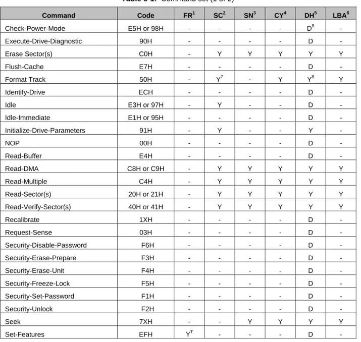
This section defines the software requirements and the format of the commands the host sends to the ATA-Disk Module (ADM). Commands are issued to the ADM by loading the required registers in the command block with the supplied parameters, and then writing the command code to the Command register. The manner in which a command is accepted varies.
Table 6-1: Command set (1 of 2)
Command Code FR1 SC2 SN3 CY4 DH5 LBA6
Check-Power-Mode E5H or 98H - - - - D8 - Execute-Drive-Diagnostic 90H - - - - D - Erase Sector(s) C0H - Y Y Y Y Y Flush-Cache E7H - - - - D - Format Track 50H - Y7 - Y Y8 Y Identify-Drive ECH - - - - D - Idle E3H or 97H - Y - - D - Idle-Immediate E1H or 95H - - - - D - Initialize-Drive-Parameters 91H - Y - - Y - NOP 00H - - - - D - Read-Buffer E4H - - - - D - Read-DMA C8H or C9H - Y Y Y Y Y Read-Multiple C4H - Y Y Y Y Y Read-Sector(s) 20H or 21H - Y Y Y Y Y Read-Verify-Sector(s) 40H or 41H - Y Y Y Y Y Recalibrate 1XH - - - - D - Request-Sense 03H - - - - D - Security-Disable-Password F6H - - - - D - Security-Erase-Prepare F3H - - - - D - Security-Erase-Unit F4H - - - - D - Security-Freeze-Lock F5H - - - - D - Security-Set-Password F1H - - - - D - Security-Unlock F2H - - - - D - Seek 7XH - - Y Y Y Y Set-Features EFH Y7 - - - D -
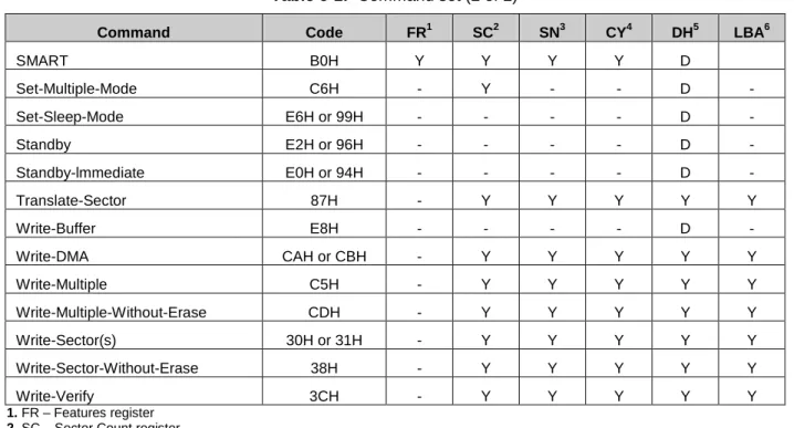
Table 6-1: Command set (2 of 2)
Command Code FR1 SC2 SN3 CY4 DH5 LBA6
SMART B0H Y Y Y Y D Set-Multiple-Mode C6H - Y - - D - Set-Sleep-Mode E6H or 99H - - - - D - Standby E2H or 96H - - - - D - Standby-lmmediate E0H or 94H - - - - D - Translate-Sector 87H - Y Y Y Y Y Write-Buffer E8H - - - - D - Write-DMA CAH or CBH - Y Y Y Y Y Write-Multiple C5H - Y Y Y Y Y Write-Multiple-Without-Erase CDH - Y Y Y Y Y Write-Sector(s) 30H or 31H - Y Y Y Y Y Write-Sector-Without-Erase 38H - Y Y Y Y Y Write-Verify 3CH - Y Y Y Y Y 1. FR – Features register 2. SC – Sector Count register 3. SN – Sector Number register 4. CY – Cylinder registers 5. DH – Drive/Head register
6. LBA – Logical Block Address mode supported (see command descriptions for use) 7. Y – The register contains a valid parameter for this command
8. For the Drive/Head register:
Y means both the ATA-Disk Module and Head parameters are used
7. Electrical Specification
Caution: Absolute Maximum Stress Ratings – Applied conditions greater than those listed under “Absolute Maximum Stress Ratings” may cause permanent damage to the device. This is a stress rating only and functional operation of the device at these conditions or conditions greater than those defined in the operational sections of this data sheet is not implied. Exposure to absolute maximum stress rating conditions may affect device reliability.
Table 7-1: Operating range
Range Ambient Temperature 3.3V 5V
Standard 0°C to +70°C
Extended Temperature -40°C to +85°C 3.135-3.465V 4.75-5.25V
Table 7-2: Absolute maximum power pin stress ratings Parameter Symbol Conditions
Input Power VDD -0.3V min. to 6.5V max.
Voltage on any pin except VDD with respect to GND V -0.5V min. to VDD + 0.5V max.
Table 7-3: Recommended system power-up timing
Symbol Parameter Typical Maximum Units
TPU-READY1 Power-up to Ready Operation 200 1000 ms
TPU-WRITE 1
Power-up to Write Operation 200 1000 ms
8. Physical Characteristics
8.1 Dimension – Mini ADM
8.1.2 44 pin/90 degree w/o jumper
Unit: ㎜
9. Product Ordering Information
9.1 Product Code Designations
AP – FM xxxx E 1 X X X S - X X X X
Hardware Setting
1: With both WP/Master Jumpers 4: Without Jumper Model Name Capacity: 0128: 128MB 0256: 256MB 0512: 512MB 001G: 1GB 002G: 2GB 004G: 4GB 008G: 8GB 016G: 16GB Controller Version Package Modifier: 44 pin / 90D PCB Version Speed: S: Standard D: High Speed Voltage: 3: 3.3V 5: 5.0V Environmental Spec Temperature: Blank: Standard W: Extended Temperature. Flash Type FW Version
9.2 Valid Combinations
StandardSingle (Standard Speed)
Dual (High Speed)
Capacity Model Number (5V) Capacity Model Number (5V)
128MB
AP-FM0128E15S5S-KS
256MBAP-FM0256E15D5S-KS
256MBAP-FM0256E15S5S-KS
512MBAP-FM0512E15D5S-KS
512MBAP-FM0512E15S5S-KS
1GBAP-FM001GE15D5S-KS
1GBAP-FM001GE15S5S-KS
2GBAP-FM002GE15D5S-KS
2GBAP-FM002GE15S5S-KS
4GBAP-FM004GE15D5S-KS
16GBAP-FM016GE15S5S-KT
8GBAP-FM008GE15D5S-KS
Capacity Model Number (3.3V) Capacity Model Number (3.3V)
128MB
AP-FM0128E15S3S-KS
256MBAP-FM0256E15D3S-KS
256MBAP-FM0256E15S3S-KS
512MBAP-FM0512E15D3S-KS
512MBAP-FM0512E15S3S-KS
1GBAP-FM001GE15D3S-KS
1GBAP-FM001GE15S3S-KS
2GBAP-FM002GE15D3S-KS
2GBAP-FM002GE15S3S-KS
4GBAP-FM004GE15D3S-KS
16GBAP-FM016GE15S3S-KT
8GBAP-FM008GE15D3S-KS
Extended TemperatureSingle (Standard Speed)
Dual (High Speed)
Capacity Model Number (5V) Capacity Model Number (5V)
128MB
AP-FM0128E15S5S-KSW
256MBAP-FM0256E15D5S-KSW
256MBAP-FM0256E15S5S-KSW
512MBAP-FM0512E15D5S-KSW
512MBAP-FM0512E15S5S-KSW
1GBAP-FM001GE15D5S-KSW
1GBAP-FM001GE15S5S-KSW
2GBAP-FM002GE15D5S-KSW
2GBAP-FM002GE15S5S-KSW
4GBAP-FM004GE15D5S-KSW
16GBAP-FM016GE15S5S-KTW
8GBAP-FM008GE15D5S-KSW
Capacity Model Number (3.3V) Capacity Model Number (3.3V)
128MB
AP-FM0128E15S3S-KSW
256MBAP-FM0256E15D3S-KSW
256MB
AP-FM0256E15S3S-KSW
512MBAP-FM0512E15D3S-KSW
512MB
AP-FM0512E15S3S-KSW
1GBAP-FM001GE15D3S-KSW
1GB
AP-FM001GE15S3S-KSW
2GBAP-FM002GE15D3S-KSW
Revision History
Revision Date Description Remark
1.0 03/07/2011 Official release
1.1 03/10/2011 Updated Product Ordering Information 1.2 03/11/2011 Updated Product Ordering Information 1.3 04/26/2011 Updated Product Ordering Information &
Global Presence
Taiwan (Headquarters)
Apacer Technology Inc.4th Fl., 75 Xintai 5th Rd., Sec.1 Hsichih, New Taipei City Taiwan 221
R.O.C.
Tel: +886-2-2698-2888 Fax: +886-2-2698-2889
U.S.A.
Apacer Memory America, Inc.386 Fairview Way, Suite102, Milpitas, CA 95035
Tel: 1-408-518-8699 Fax: 1-408-935-9611
Japan
Apacer Technology Corp.5F, Matsura Bldg., Shiba, Minato-Ku Tokyo, 105-0014, Japan
Tel: 81-3-5419-2668 Fax: 81-3-5419-0018
Europe
Apacer Technology B.V.Aziëlaan 22, 5232 BA 's-Hertogenbosch, The Netherlands Tel: 31-73-645-9620 Fax: 31-73-645-9629 [email protected]
China
Apacer Electronic (Shanghai) Co., Ltd1301, No.251,Xiaomuqiao Road, Shanghai, 200032, China
Tel: 86-21-5529-0222 Fax: 86-21-5206-6939
India
Apacer Technologies Pvt Ltd,#1064, 1st Floor, 7th ‘A’ Main,
3rd Block Koramangala, Bangalore – 560 034 Tel: +91 80 4152 9061/62/63
Fax: +91 80 4170 0215