Concurrent Round-Robin-Based Dispatching
Schemes for Clos-Network Switches
Eiji Oki, Member, IEEE, Zhigang Jing, Member, IEEE, Roberto Rojas-Cessa, Member, IEEE, and
H. Jonathan Chao, Fellow, IEEE
Abstract—A Clos-network switch architecture is attractive because of its scalability. Previously proposed implementable dispatching schemes from the first stage to the second stage, such as random dispatching (RD), are not able to achieve high throughput unless the internal bandwidth is expanded. This paper presents two round-robin-based dispatching schemes to overcome the throughput limitation of the RD scheme. First, we introduce a concurrent round-robin dispatching (CRRD) scheme for the Clos-network switch. The CRRD scheme provides high switch throughput without expanding internal bandwidth. CRRD implementation is very simple because only simple round-robin arbiters are adopted. We show via simulation that CRRD achieves 100% throughput under uniform traffic. When the offered load reaches 1.0, the pointers of round-robin arbiters at the first- and second-stage modules are completely desynchronized and contention is avoided. Second, we introduce a concurrent master–slave round-robin dispatching (CMSD) scheme as an improved version of CRRD to make it more scalable. CMSD uses hierarchical round-robin arbitration. We show that CMSD preserves the advantages of CRRD, reduces the scheduling time by 30% or more when arbitration time is significant and has a dramatically reduced number of crosspoints of the intercon-nection wires between round-robin arbiters in the dispatching scheduler with a ratio of1 , where is the switch size. This makes CMSD easier to implement than CRRD when the switch size becomes large.
Index Terms—Arbitration, Clos-network switch, dispatching, packet switch, throughput.
I. INTRODUCTION
A
S THE Internet continues to grow, high-capacity switches and routers are needed for backbone networks. Several ap-proaches have been presented for high-speed packet switching systems [2], [3], [13]. Most high-speed packet switching sys-tems use a fixed-sized cell in the switch fabric. Variable-length packets are segmented into several fixed-sized cells when they arrive, switched through the switch fabric and reassembled into packets before they depart.Manuscript received December 14, 2000; revised November 1, 2001; ap-proved by IEEE/ACM TRANSACTIONS ONNETWORKINGEditor N. McKeown. This work was supported in part by the New York State Center for Advanced Technology in Telecommunications (CATT), and in part by the National Sci-ence Foundation under Grant 9906673 and Grant ANI-9814856.
E. Oki was with the Polytechnic University of New York, Brooklyn, NY 11201 USA. He is now with the NTT Network Innovation Laboratories, Tokyo 180-8585, Japan (e-mail: [email protected]).
Z. Jing and H. J. Chao are with the Department of Electrical Engineering, Polytechnic University of New York, Brooklyn, NY 11201 USA (e-mail: [email protected]; [email protected]).
R. Rojas-Cessa was with the Department of Electrical Engineering, Poly-technic University of New York, Brooklyn, NY 11201 USA. He is now with the Department of Electrical and Computer Engineering, New Jersey Institute of Technology, Newark, NJ 07102 USA (e-mail: [email protected]).
Digital Object Identifier 10.1109/TNET.2002.804823
For implementation in a high-speed switching system, there are mainly two approaches. One is a single-stage switch archi-tecture. An example of the single-stage architecture is a crossbar switch. Identical switching elements are arranged on a matrix plane. Several high-speed crossbar switches are described [4], [13], [16]. However, the number of I/O pins in a crossbar chip limits the switch size. This makes a large-scale switch difficult to implement cost effectively as the number of chips becomes large.
The other approach is to use a multiple-stage switch archi-tecture, such as a Clos-network switch [7]. The Clos-network switch architecture, which is a three-stage switch, is very attrac-tive because of its scalability. We can categorize the Clos-net-work switch architecture into two types. One has buffers to store cells in the second-stage modules and the other has no buffers in the second-stage modules.
Reference [2] demonstrated a gigabit asynchronous transfer mode (ATM) switch using buffers in the second stage. In this architecture, every cell is randomly distributed from the first stage to the second-stage modules to balance the traffic load in the second stage. The purpose of implementing buffers in the second-stage modules is to resolve contention among cells from different first-stage modules [18]. The internal speed-up factor was suggested to be set more than 1.25 in [2]. However, this requires a re-sequence function at the third-stage modules or the latter modules because the buffers in the second-stage modules cause an out-of-sequence problem. Furthermore, as the port speed increases, this re-sequence function makes a switch more difficult to implement.
Reference [6] developed an ATM switch by using non-buffered second-stage modules. This approach is promising even if the port line speed increases because it does not cause the out-of-sequence problem. Since there is no buffer in the second-stage modules to resolve the contention, how to dis-patch cells from the first to second stage becomes an important issue. There are some buffers to absorb contention at the first and third stages.1
A random dispatching (RD) scheme is used for cell dis-patching from the first to second stage [6], as it is adopted in the case of the buffered second-stage modules in [2]. This scheme attempts to distribute traffic evenly to the second-stage modules. However, RD is not able to achieve a high throughput unless the internal bandwidth is expanded because the con-tention at the second stage cannot be avoided. To achieve 100%
1Although there are several studies on scheduling algorithms [9], [10] where
every stage has no buffer, the assumption used in the literature is out of the scope of this paper. This is because the assumption requires a contention resolution function for output ports (OPs) before cells enter the Clos-network switch. This function is not easy to implement in high-speed switching systems.
throughput under uniform traffic2 by using RD, the internal
expansion ratio has to be set to approximately 1.6 when the switch size is large [6].
One question arises: Is it possible to achieve a high throughput by using a practical dispatching scheme without allocating any buffers in the second stage to avoid the out-of-sequence problem and without expanding the internal bandwidth?
This paper presents two solutions to this question. First, we introduce an innovative dispatching scheme called the concurrent round-robin dispatching (CRRD) scheme for a Clos-network switch. The basic idea of the novel CRRD scheme is to use the desynchronization effect [11] in the Clos-network switch. The desynchronization effect has been studied using such simple scheduling algorithms as [11], [14] and dual round-robin matching (DRRM) [4], [5] in an input-queued crossbar switch. CRRD provides high switch throughput without increasing internal bandwidth and its im-plementation is very simple because only simple round-robin arbiters are employed. We show via simulation that CRRD achieves 100% throughput under uniform traffic. With slightly unbalanced traffic, we also show that CRRD provides a better performance than RD.
Second, this paper describes a scalable round-robin-based dispatching scheme, called the concurrent master–slave round-robin dispatching (CMSD) scheme. CMSD is an improved version of CRRD that provides more scalability. To make CRRD more scalable while preserving CRRD’s advantages, we introduce two sets of output-link round-robin arbiters in the first-stage module, which are master arbiters and slave arbiters. These two sets of arbiters operate in a hierarchical round-robin manner. The dispatching scheduling time is reduced, as is the interconnection complexity of the dispatching scheduler. This makes the hardware of CMSD easier to implement than that of CRRD when the switch size becomes large. In addition, CMSD preserves the advantage of CRRD where the desynchronization effect is obtained in a Clos-network switch. Simulation suggests that CMSD also achieves 100% throughput under uniform traffic without expanding internal switch capacity.
Fig. 1 categorizes several scheduling schemes and shows the analogy of our proposed schemes. In crossbar switches , a round-robin-based algorithm, was developed to overcome the throughput limitation of the parallel iterative matching (PIM) al-gorithm [1], which uses randomness. In Clos-network switches, CRRD and CMSD, two round-robin-based algorithms, are de-veloped to overcome the throughput limitation and the high im-plementation complexity of RD, which also uses randomness.
The remainder of this paper is organized as follows. Sec-tion II describes a Clos-network switch model that we reference throughout this paper. Section III explains throughput limita-tion of RD. Seclimita-tion IV introduces CRRD. Seclimita-tion V describes CMSD as an improved version of CRRD. Section VI presents a performance study of CRRD and CMSD. Section VII discusses
2A switch can achieve 100% throughput under uniform traffic if the switch
is stable. The stable sate is defined in [12] and [15]. Note that the 100% defini-tion in [15] is more general than the one used here because all independent and admissible arrivals are considered in [15].
Fig. 1. Analogy among scheduling schemes.
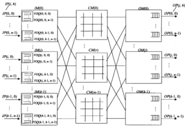
Fig. 2. Clos-network switch with VOQs in the IMs.
implementation of CRRD and CMSD. Section VIII summarizes the key points.
II. CLOS-NETWORKSWITCHMODEL
Fig. 2 shows a three-stage Clos-network switch. The termi-nology used in this paper is as follows.
IM Input module at the first stage. CM Central module at the second stage. OM Output module at the third stage.
Number of input ports (IPs)/OPs in each IM/OM, respectively.
Number of IMs/OMs. Number of CMs.
IM number, where .
OM number, where .
IP/OP number in each IM/OM, respectively,
where . CM number, where . ( )th IM. ( )th CM. ( )th OM. ( )th IP at . ( )th OP at .
Virtual output queue (VOQ) at that stores cells destined for .
Output link at that is connected to .
Output link at that is connected to .
The first stage consists of IMs, each of which has dimension. The second stage consists of bufferless CMs, each of which has dimension. The third stage consists of OMs, each of which has dimension.
An has VOQs to eliminate head-of-line (HOL)
blocking. A VOQ is denoted as . Each
stores cells that go from to the OP at . A VOQ can receive at most cells from IPs and can send one cell to a CM in one cell time slot.3
Each has output links. Each output link is
connected to each .
A has output links, each of which is denoted as , which are connected to OMs, each of which is .
An has OPs, each of which is and has an
output buffer.4 Each output buffer receives at most cells at
one cell time slot and each OP at the OM forward one cell in a first-in-first-out (FIFO) manner to the output line.5
III. RD SCHEME
The ATLANTA switch, developed by Lucent Technologies, uses the random selection in its dispatching algorithm [6]. This section describes the basic concept and performance character-istics of the RD scheme. This description helps to understand the CRRD and CMSD schemes.
A. RD Algorithm
Two phases are considered for dispatching from the first to second stage. The details of RD are described in [6]. We show an example of RD in Section III-B. In phase 1, up to VOQs from each IM are selected as candidates and a selected VOQ is assigned to an IM output link. A request that is associated with this output link is sent from the IM to the CM. This matching between VOQs and output links is performed only within the IM. The number of VOQs that are chosen in this matching is
always , where is the number of nonempty
VOQs. In phase 2, each selected VOQ that is associated with each IM output link sends a request from the IM to CM. CMs respond with the arbitration results to IMs so that the matching between IMs and CMs can be completed.
• Phase 1: Matching within IM
— Step 1: At each time slot, nonempty VOQs send re-quests for candidate selection.
— Step 2: selects up to requests out of
nonempty VOQs. For example, a round-robin arbi-tration can be employed for this selection [6]. Then, proposes up to candidate cells to randomly selected CMs.
3AnL-bit cell must be written to or read from a VOQ memory in a time less
thanL=C(n + 1), where C is a line speed. For example, when L = 6428 bits,
C = 10 Gbit/s and n = 8, L=C(n + 1) is 5.6 ns. This is feasible when we
consider current available CMOS technologies.
4We assume that the output buffer size atOP(j; h) is large enough to avoid
cell loss without flow control between IMs and OMs so that we can focus the discussion on the properties of dispatching schemes in this paper. However, the flow control mechanism can be adopted between IMs and OMs to avoid cell loss when the output buffer size is limited.
5Similar to the VOQ memory, anL-bit cell must be written to or read from
an output memory in a time less thanL=C(m + 1).
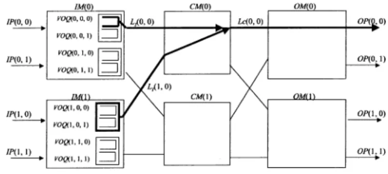
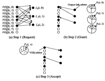
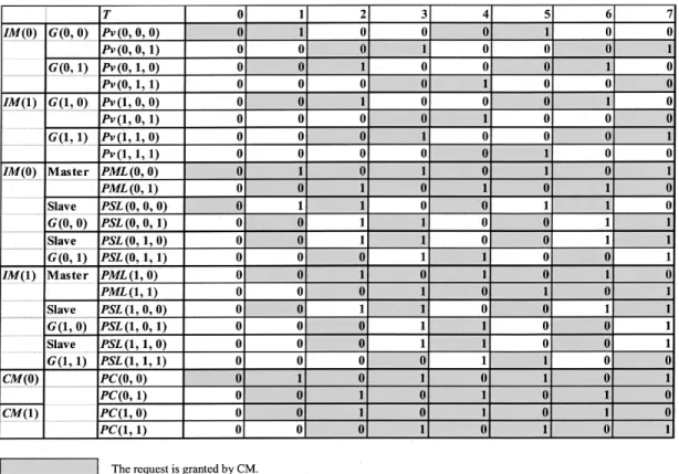
Fig. 3. Example of RD scheme (n = m = k = 2). • Phase 2: Matching between IM and CM
— Step 1: A request that is associated with is
sent out to the corresponding . A has
output links , each of which corresponds to an . An arbiter that is associated with
selects one request among requests. A random-selec-tion scheme is used for this arbitrarandom-selec-tion.6 sends
up to grants, each of which is associated with one , to the corresponding IMs.
— Step 2: If a VOQ at the IM receives the grant from the CM, it sends the corresponding cell at next time slot. Otherwise, the VOQ will be a candidate again at step 2 in phase 1 at the next time slot.
B. Performance of RD Scheme
Although RD can dispatch cells evenly to CMs, a high switch throughput cannot be achieved due to the contention at the CM, unless the internal bandwidth is expanded. Fig. 3 shows an ex-ample of the throughput limitation in the case of
. Let us assume that every VOQ is always occupied with cells. Each VOQ sends a request for a candidate at every time slot.
We estimate how much utilization an output link
can achieve for the cell transmission.7 Since the utilization
of every is the same, we focus only on a single one,
i.e., . The link utilization of is obtained
from the sum of the cell-transmission rates of
and . First, we estimate how much traffic
can send through . The probability that
uses to request for is 1/4
because there are four VOQs in . Consider that
requests for using . If either
or requests for through ,
a contention occurs with the request by at
. The aggregate probability that either
or , among four VOQs in , requests for
through is 1/2. In this case, the winning probability of is 1/2. If there is no contention
for caused by requests in , can
always send a cell with a probability of 1.0 without contention.
6Even when the round-robin scheme is employed as the contention resolution
function forL (r; j) at CM(r), the result that we will discuss later is the same as the random selection due to the effect of the RD.
7The output-link utilization is defined as the probability that the output link
is used in cell transmission. Since we assume that the traffic load destined for each OP is not less than 1.0, we consider the maximum switch throughput as the output-link utilization throughout this paper, unless specifically stated oth-erwise.
Therefore, the traffic that can send through is given as follows:
(1)
Since can use either or (i.e., two
CMs) and is in the same situation as (i.e., two VOQs), the total link utilization of is
(2)
Thus, in this example of , the switch can
achieve a throughput of only 75%, unless the internal bandwidth is expanded.
This observation can be generally extended. We derive the formula that gives the maximum throughput by using RD under uniform traffic in the following equation:
(3) We describe how to obtain in detail in Appendix A. The factor in (3) expresses the expansion ratio.
When the expansion ratio is 1.0 (i.e., ), the maximum throughput is only a function of . As described in the above example of , the maximum throughput is 0.75. As in-creases, the maximum throughput decreases. When , the maximum throughput tends to
(see Appendix B). In other words, to achieve 100% throughput by using RD, the expansion ratio has to be set to at least
.
IV. CRRD SCHEME
A. CRRD Algorithm
The switch model described in this section is the same as the one described in Section II. However, to simplify the
explana-tion of CRRD, the order of in is rearranged
for dispatching as follows:
Fig. 4. CRRD scheme.
Therefore, is redefined as , where
and .8
Fig. 4 illustrates the detailed CRRD algorithm by showing an example. To determine the matching between a request from and the output link , CRRD uses an itera-tive matching in . In , there are output-link round-robin arbiters and VOQ round-robin arbiters. An output-link arbiter associated with and has its own pointer . A VOQ arbiter associated with has its own pointer . In , there are round-robin arbiters, each of which corresponds to and has its own pointer .
As described in Section III-A, two phases are also considered in CRRD. In phase 1, CRRD employs an iterative matching by using round-robin arbiters to assign a VOQ to an IM output link. The matching between VOQs and output links is performed within the IM. It is based on a round-robin arbitration and is similar to the request/grant/accept approach. A major difference is that in CRRD, a VOQ sends a request to every output-link arbiter; in , a VOQ sends a request to only the destined output-link arbiter. In phase 2, each selected VOQ that is matched with an output link sends a request from the IM to the CM. CMs send the arbitration results to IMs to complete the matching between the IM and CM.
• Phase 1: Matching within IM — First iteration
* Step 1: Each nonempty VOQ sends a request to every output-link arbiter.
* Step 2: Each output-link arbiter chooses one nonempty VOQ request in a round-robin fashion by searching from the position of . It then sends the grant to the selected VOQ.
* Step 3: The VOQ arbiter sends the accept to the granting output-link arbiter among all those received in a round-robin fashion by searching from the
posi-tion of .
— th iteration ( )9
8The purpose of redefining the VOQs is to easily obtain the desynchronization
effect.
9The number of iterations is designed by considering the limitation of the
arbitration time in advance. CRRD tries to choose as many nonempty VOQs in this matching as possible, but it does not always choose the maximum available nonempty VOQs if the number of iterations is not enough. On the other hand, RD can choose the maximum number of nonempty VOQs in phase 1.
Fig. 5. Example of desynchronization effect of CRRD (n = m = k = 2). * Step 1: Each unmatched VOQ at the previous iterations
sends another request to all unmatched output-link ar-biters.
* Steps 2 and 3: The same procedure is performed as in the first iteration for matching between unmatched nonempty VOQs and unmatched output links. • Phase 2: Matching between IM and CM
— Step 1: After phase 1 is completed, sends the request to . Each round-robin arbiter associated with then chooses one request by searching from the position of and sends the grant to
of .
— Step 2: If the IM receives the grant from the CM, it sends a corresponding cell from that VOQ at the next time slot. Otherwise, the IM cannot send the cell at the next time slot. The request from the CM that is not granted will again be attempted to be matched at the next time slot because the pointers that are related to the ungranted requests are not moved.
As with , the round-robin pointers and
in and in are updated to one
position after the granted position only if the matching within the IM is achieved at the first iteration in phase 1 and the request is also granted by the CM in phase 2.
Fig. 4 shows an example of , where CRRD
operates at the first iteration in phase 1. At step 1, ,
, , and , which are nonempty
VOQs, send requests to all the output-link arbiters. At step 2, output-link arbiters that are associated with , ,
and select , , and ,
respectively, according to their pointers’ positions. At step 3, receives two grants from both output-link arbiters
of and and accepts by using its
own VOQ arbiter. Since receives one grant from output-link arbiter , it accepts the grant. With one iteration, cannot be matched with any nonempty VOQs. At the next iteration, the matching between unmatched nonempty VOQs and will be performed.
B. Desynchronization Effect of CRRD
While RD causes contention at the CM, as described in Appendix A, CRRD decreases contention at the CM because
pointers , , and are desynchronized.
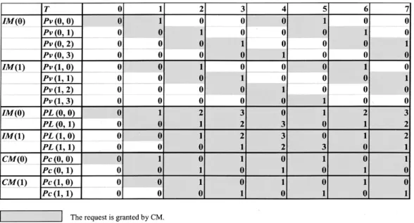
We demonstrate how the pointers are desynchronized by using simple examples. Let us consider the example of , as shown in Fig. 5. We assume that every VOQ is always occupied with cells. Each VOQ sends a request to be selected as a candidate at every time slot. All the pointers
are set to be , , and at the
initial state. Only one iteration in phase 1 is considered here. At time slot , since all the pointers are set to zero, only
one VOQ in , which is , can send a cell with
through . The related pointers with the grant
, , and are updated from zero to one.
At , three VOQs, which are , ,
and , can send cells. The related pointers with the grants are updated. Four VOQs can send cells at . In this situation, 100% switch throughput is achieved. There is no contention at all at the CMs from because the pointers are desynchronized.
Similar to the above example, CRRD can achieve the desyn-chronization effect and provide high throughput even though the switch size is increased.
V. CMSD SCHEME
CRRD overcomes the problem of limited switch throughput of the RD scheme by using simple round-robin arbiters. CMSD is an improved version of CRRD that preserves CRRD’s advan-tages and provides more scalability.
A. CMSD Algorithm
Two phases are also considered in the description of the CMSD scheme, as in the CRRD scheme. The difference
be-(a) (b)
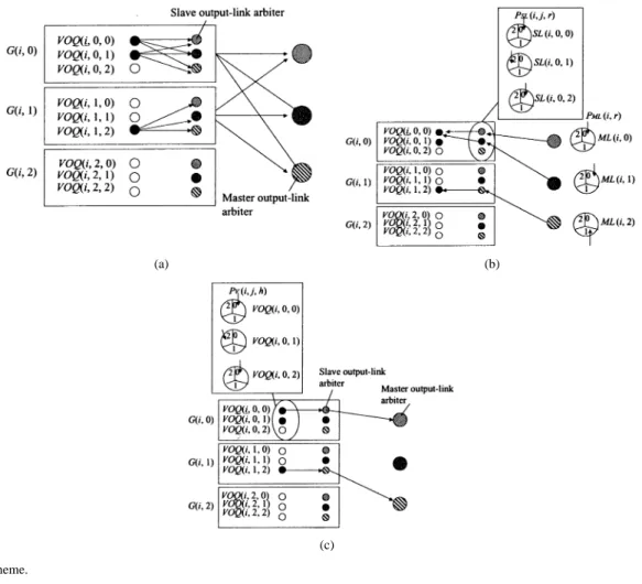
(c) Fig. 6. CMSD scheme.
tween CMSD and CRRD is how the iterative matching within the IM operates in phase 1.
We define several notations to describe the CMSD algorithm, which is shown in an example in Fig. 6. is denoted as a VOQ group that consists of VOQs, each of which is
de-noted as . In , there are master output-link
round-robin arbiters, slave output-link round-robin arbiters, and VOQ round-robin arbiters. Each master output-link
ar-biter associated with is denoted as and has
its own pointer . Each slave output-link arbiter
asso-ciated with and is denoted as and
has its own pointer . A VOQ arbiter associated with
has its own pointer .
• Phase 1: Matching within IM — First iteration
* Step 1: There are two sets of requests issued to the output-link arbiters. One set is a request that is
sent from a nonempty to every
asso-ciated within . The other set is a
group-level request sent from that has at least
one nonempty VOQ to every .
* Step 2: Each chooses a request among
VOQ groups independently in a round-robin fashion by searching from the position of and sends the grant to that belongs to the selected . receives the grant from its master arbiter and selects one VOQ request in a round-robin
fashion by searching from the position of 10
and sends the grant to the selected VOQ.
* Step 3: The VOQ arbiter sends the accept to the granting master and slave output-link arbiters among all those received in a round-robin fashion by searching
from the position of .
— th iteration ( )
* Step 1: Each unmatched VOQ at the previous itera-tions sends a request to all the slave output-link ar-biters again. , which has at least one unmatched nonempty VOQ, sends a request to all the unmatched master output-link arbiters again.
* Steps 2 and 3: The same procedure is performed as in the first iteration for matching between the unmatched nonempty VOQs and unmatched output links. • Phase 2: Matching between IM and CM
This operation is the same as in CRRD.
As with CRRD, the round-robin pointers ,
, and in and in
are updated to one position after the granted position only if the matching within the IM is achieved at the first iteration in phase 1 and the request is also granted by the CM in phase 2.
Fig. 6 shows an example of , where
CMSD is used at the first iteration in phase 1. At step 1,
10In the actual hardware design,SL(i; j; r) can start to search for a VOQ
request without waiting to receive the grant from a master arbiter. IfSL(i; j; r) does not receive a grant, the search bySL(i; j; r) is invalid. This is an advantage of CMSD. Section VII-A discusses the dispatching scheduling time.
Fig. 7. Example of the desynchronization effect (n = m = k = 2).
, , and , which are
nonempty VOQs, send requests to the associated slave output-link arbiters. and send requests to all the master output-link arbiters. At step 2, , , and
select , , and , respectively,
ac-cording to the pointers’ positions. , , and
, which belong to the selected VOQ groups, choose
, , and , respectively. At
step 3, receives two grants from both
and . It accepts by using its own VOQ
arbiter. Since receives one grant from ,
it accepts the grant. In this iteration, is not matched with any nonempty VOQs. At the next iteration, the matching
between an unmatched nonempty VOQ and will be
performed.
B. Desynchronization Effect of CMSD
CMSD also decreases contention at the CM because pointers
, , , and are
desynchro-nized.
We illustrate how the pointers are desynchronized by using simple examples. Let us consider the example of
, as shown in Fig. 7. We assume that every VOQ is al-ways occupied with cells. Each VOQ sends a request to be se-lected as a candidate at every time slot. All the pointers are set
to be , , , and
at the initial state. Only one iteration in phase 1 is considered here.
At time slot , since all the pointers are set to zero, only
one VOQ in , which is , can send a cell with
through . The related pointers with the grant
, , and are updated from zero to one.
At , three VOQs, which are , ,
and can send cells. The related pointers with the grants are updated. Four VOQs can send cells at . In this situation, 100% switch throughput is achieved. There is no contention at the CMs from because the pointers are desynchronized.
Similar to the above example, CMSD can also achieve the desynchronization effect and provide high throughput even though the switch size is increased, as in CRRD.
VI. PERFORMANCE OFCRRDANDCMSD
The performance of CRRD and CMSD was evaluated by sim-ulation using uniform and nonuniform traffic.
A. Uniform Traffic
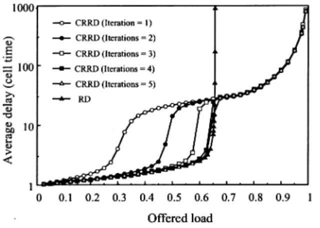
1) CRRD: Fig. 8 shows that CRRD provides higher throughput than RD under uniform traffic. A Bernoulli arrival process is used for input traffic. Simulation suggests that CRRD can achieve 100% throughput for any number of iterations in IM.
The reason CRRD provides 100% throughput under uniform traffic is explained as follows. When the offered load is 1.0 and if the idle state, in which the internal link is not fully utilized, still occurs due to contention in the IM and CM, a VOQ that fails in the contention has to store backlogged cells. Under uniform traffic, every VOQ keeps backlogged cells until the idle state is eliminated, i.e., until the stable state is reached. The stable state is defined in [12]. In the stable state, every VOQ is occupied with backlogged cells. In this situation, as illustrated in Fig. 5,
Fig. 8. Delay performance of CRRD and RD schemes (n = m = k = 8). the desynchronization effect is always obtained. Therefore, even when the offered load is 1.0, no contention occurs in the stable state.
As the number of iterations increases, the delay performance improves when the offered load is less than 0.7, as shown in Fig. 8. This is because the matching between VOQs and output links within the IM increases. When the offered traffic load is not heavy, the desynchronization of the pointers is not completely achieved. At the low offered load, the delay per-formance of RD is better than that of CRRD with one itera-tion. This is because the matching within the IM in CRRD is not completely achieved, while the complete matching within the IM in RD is always achieved, as described in Section III-A. When the offered load is larger than 0.7, the delay performance of CRRD is not improved by the number of iterations in the IM. The number of iterations in the IM only improves the matching within the IM, but does not improve the matching between the IM and CM. The delay performance is improved by the number of iterations in the IM when the offered load is not heavy. Fig. 8 shows that, when the number of iterations in the IM increases to four, the delay performances almost converge.
Fig. 9 shows that 99.9% delay of CRRD has the same ten-dency as the average delay, as shown in Fig. 8.
Our simulation shows, as presented in Fig. 10, that even when the input traffic is bursty, CRRD provides 100% throughput for any number of iterations. However, the delay performance under the bursty traffic becomes worse than that of the non-bursty traffic at the heavy load condition. The reason for the 100% throughput even for bursty traffic can be explained as de-scribed in the Bernoulli traffic discussion above. We assume that the burst length is exponentially distributed as the bursty traffic. In this evaluation, the burst length is set to ten.
By looking at Fig. 10, we can make the following observa-tions.
When the input offered load , where is very low, the number of iterations does not affect the delay performance sig-nificantly. This is because average match size ratios for the matching within the IM in phase 1 and for the matching between the IM and CM in phase 2 are close to 1.0, as shown in Figs. 11 and 12.
The average match size ratios and are defined as follows.
Fig. 9. 99.9% delay of CRRD (n = m = k = 8).
Fig. 10. Delay performance of CRRD affected by bursty traffic (n = m =
k = 8).
Fig. 11. Average match size ratioR in phase 1 (n = m = k = 8). is defined as
(4)
where is a match size within in phase
1 and is the number of nonempty VOQs in
at each time slot. When ,
is set to 1.0. Note that RD always
provides , as is described in
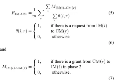
Fig. 12. Average match size ratioR in phase 2 (n = m = k = 8). is defined as
(5) if there is a request from
to otherwise
(6) and
if there is a grant from to in phase 2
otherwise
(7)
When , is set to
1.0.
When increases to approximately 0.4, of CRRD with one iteration for Bernoulli traffic decreases due to contention in the IM. for the bursty traffic is not more affected by than for Bernoulli traffic. The desynchronization effect is more difficult to obtain for Bernoulli traffic than for bursty traffic be-cause the arrival process is more independent. In this load re-gion, where the traffic load is approximately 0.4, the delay per-formance with one iteration for Bernoulli traffic is worse than for bursty traffic.
At , the number of iterations affects the delay performance for Bernoulli traffic, as shown in Fig. 10. In this load region, with one iteration for Bernoulli traffic is low, as shown in Fig. 11, while with four iterations is nearly 1.0. On the other hand, at , the number of iterations affects the delay performance for the bursty traffic, as shown in Fig. 10. In this load region, with one iteration for the bursty traffic is low, as shown in Fig. 11, while with four iterations is nearly 1.0.
When the traffic load becomes very heavy, and
with any iterations for both Bernoulli and bursty traffic approach 1.0. In this load region, the desynchronization effect is easy to obtain, as described above.
Fig. 13. Delay performance of CMSD compared with CRRD (n = m = k =
8).
2) CMSD: This section describes the performance of CMSD under uniform traffic by comparing it to CRRD.
Fig. 13 shows that CMSD provides 100% throughput under uniform traffic, as CRRD does, due to the desynchronization effect, as described in Section V-B. The throughput of CMSD is also independent of the number of iterations in the IM.
In Fig. 13, the number of iterations in the IM improves the delay performance even in heavy load regions in the CMSD scheme. On the other hand, the delay performance of CRRD is improved by the number of iterations in the IM when the offered load is not heavy. As a result, in the heavy load region, the delay performance of CMSD is better than that of CRRD when the number of iterations in the IM is large.
Since the master output-link arbiter of CMSD can choose a VOQ group, not a VOQ itself in CRRD, the master output-link arbiter of CMSD affects the matching between the IM and CM more than the output-link arbiter of CRRD. Therefore, CMSD makes the matching between the IM and CM more efficient than CRRD when the number of iterations in the IM increases. Al-though this is one of the advantages of CMSD, the main advan-tage is that CMSD is easier to implement than CRRD when the switch size increases; this will be described in Section VII.
Fig. 13 shows that when the number of iterations in the IM increases to four for CMSD, the delay performance almost con-verges.
Fig. 14 shows via simulation that CMSD also provides 100% throughput under uniform traffic even when a bursty arrival process is considered. The bursty traffic assumption in Fig. 14 is the same as that in Fig. 10.
In the heavy-load region, the delay performance of CMSD is better than that of CRRD under bursty traffic when the number of iterations in the IM is large.
3) Expansion Factor: Fig. 15 shows that RD requires an ex-pansion ratio of over 1.5 to achieve 100% throughput, while CRRD and CMSD need no bandwidth expansion.
B. Nonuniform Traffic
We compared the performance of CRRD, CMSD, and RD using nonuniform traffic. The nonuniform traffic considered here is defined by introducing unbalanced probability, . Let us
Fig. 14. Delay performance of CMSD in bursty traffic compared with CRRD (n = m = k = 8).
Fig. 15. Relationship between switch throughput and expansion factor (n =
k = 8).
consider IP , OP , and the offered input load for each IP . The traffic load from IP to OP , is given by
if otherwise
(8)
where is the switch size. Here, the aggregate offered load that goes to output from all the IPs is given by
(9) When , the offered traffic is uniform. On the other hand, when , it is completely unbalanced. This means that all the traffic of IP is destined for only OP , where .
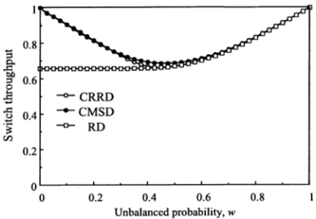
Fig. 16 shows that the throughput with CRRD and CMSD is higher than that of RD when the traffic is slightly unbalanced.11
The throughput of CRRD is almost the same as that of CMSD. We assume that enough large numbers of iterations in the IM are adopted in this evaluation for both CRRD and CMSD schemes to observe how nonuniform traffic impacts the matching
be-tween the IM and CM. From to around , the
throughput of CRRD and CMSD decreases. This is because the complete desynchronization of the pointers is hard to achieve under unbalanced traffic.12However, when is larger than 0.4, 11Although both results shown in Fig. 16 are obtained by simulation, we also
analytically derived the upper bound throughput of RD in Appendix C.
12For the same reason, when input traffic is very asymmetric, throughput
degradation occurs.
Fig. 16. Switch throughput under nonuniform traffic (n = m = k = 8). the throughput of CRRD and CMSD increases because the con-tention at the CM decreases. The reason is that, as increases, more traffic from is destined for by using
and less traffic from is destined for by using , where , according to (8). That is why contention
of at decreases.
Due to the desynchronization effect, both CRRD and CMSD provide better performance than RD when is smaller than 0.4. In addition, the throughput of CRRD and CMSD is not worse than that of RD at any larger than 0.4, as shown in Fig. 16.
Developing a new practical dispatching scheme that avoids the throughput degradation even under nonuniform traffic without expanding the internal bandwidth is for further study.
VII. IMPLEMENTATION OFCRRDANDCMSD
This section discusses the implementation of CRRD and CMSD. First, we briefly compare them to RD. Since the CRRD and CMSD schemes are based on round-robin arbitration, their implementations are much simpler than that of RD which needs random generators in the IMs. These generator are difficult and expensive to implement at high speeds [14]. Therefore, the implementation cost for CRRD and CMSD is reduced compared to RD.
The following sections describe the dispatching scheduling time, hardware complexity, and interconnection-wire com-plexity for CRRD and CMSD.
A. Dispatching Scheduling Time
1) CRRD: In phase 1, at each iteration, two round-robin ar-biters are used. One is an output-link arbiter that chooses one VOQ request out of, at most, requests. The other is a VOQ ar-biter that chooses one grant from, at most, output-link grants. We assume that priority encoders are used for the implementa-tion of the round-robin arbiters [14]. Since , the dis-patching scheduling time complexity of each iteration in phase 1 is (see Appendix D) [8]. As is the case of , ideally, iterations in phase 1 are preferable because there are output links that should be matched with VOQs in the IM. Therefore, the time complexity in phase 1 is . How-ever, we do not practically need iterations. As described in Section VI, simulation suggests that one iteration is sufficient to achieve 100% throughput under uniform traffic. In this case,
increasing the number of iterations improves the delay perfor-mance.
In phase 2, one IM request is chosen from, at most, requests. The time complexity at phase 2 is .
As a result, the time complexity of CRRD is
, where is the number of switch ports. If we set the number of iterations in phase 1 as , where , for practical purposes, the time complexity of CRRD is expressed
as .
Next, we consider the required dispatching scheduling time of CRRD. The required time of CRRD, i.e., , is approximately
(10) where is a constant coefficient, which is determined by device technologies. is the transmission delay between arbiters. 2) CMSD: In phase 1, at each iteration, three round-robin arbiters are used. The first one is a master output-link arbiter that chooses one out of VOQ group requests. The second one is a slave output-link arbiter that chooses one out of re-quests. The third one is a VOQ arbiter that chooses one out of output-link grants. The slave output-link arbiter can per-form its arbitration without waiting for the result in the master output-link arbitration, as described in Section V-A. In other words, both master output-link and slave output-link arbiters operate simultaneously. Since is satisfied, the longer arbitration time of either the master output-link arbitration or the VOQ arbitration time is dominant. Therefore, the time
com-plexity of each iteration in phase 1 is .
The time complexity in phase 1 is if
iterations are adopted.
In phase 2, one is chosen out of IM requests. The dis-patching scheduling time complexity at phase 2 is .
As a result, the time complexity of CMSD is
. As in the case of CRRD, for practical purposes, the time complexity of CMSD is expressed
as . When we assume ,
the time complexity of CMSD is , which is
equivalent to . This is the same order of time complexity as CRRD.
We consider the required dispatching scheduling time of CMSD. With the same assumption as CRRD, the required time
of CMSD, i.e., , is approximately
(11) where is the transmission delay between arbiters.
3) Comparison of Required Dispatching Scheduling Times: Although the order of the scheduling time complexity of CRRD is the same as that of CMSD, the required times are different. To compare both required times, we define the ratio
of to as follows:
(12) First, we assume that the transmission delay between arbiters and is negligible compared to the required
TABLE I
RATIO OFT (CMSD)TOT (CRRD), R (n = k = m)
round-robin execution time to clarify the dependency on , , and so that we can further eliminate the device-dependent factor . Using (10)–(12), we obtain the following equation:
(13) Table I shows the relationship between and when we
assume . Note that when , depends
only on and is independent of .13
When , for example, the required time of CMSD is reduced more than 30% compared to CRRD.
In (13), we ignored the factors of and . When and are large, the reduction effect of CMSD in Table I decreases. As the distance between two arbiters gets larger, these factors become significant.
B. Hardware Complexity for Dispatching in the IM
Since the CM arbitration algorithm of CMSD is the same as that of CRRD, we discuss hardware complexities in the IM only. 1) CRRD: According to implementation results presented in [14], the hardware complexity for each round-robin arbiter is , where is the number of requests to be selected by the arbiter.
Each IM has output-link arbiters and VOQ arbiters. Each output-link arbiter chooses one out of requests. The hardware complexity for all the output-link arbiters is . Each VOQ arbiter chooses one out of requests. The hardware complexity for all the VOQ arbiters is . Therefore, the hardware complexity of CRRD in the IM is .
2) CMSD: Each IM has master output-link arbiters and slave output-link arbiters VOQ arbiters. Each master output-link arbiter chooses one out of requests. The hardware complexity for all the master output-link arbiters is . Each slave output-link arbiter chooses one out of requests. The hardware complexity for all the slave output-link arbiters is . Each VOQ chooses one out of requests. The hard-ware complexity for all the VOQ arbiters is . Therefore, the hardware complexity of CMSD in the IM is . Thus, the order of the hardware complexity of CMSD is the same as that of CRRD.
C. Interconnection-Wire Complexity Between Arbiters 1) CRRD: In CRRD, each VOQ arbiter is connected to all output-link arbiters with three groups of wires. The first group is used by a VOQ arbiter to send requests to the output-link arbiters. The second one is used by a VOQ arbiter to receive grants from the output-link arbiters. The third one is used by a VOQ arbiter to send grants to the output-link arbiters.
As the switch size is larger, the number of wires that connect all the VOQ arbiters with all the output-link arbiters becomes
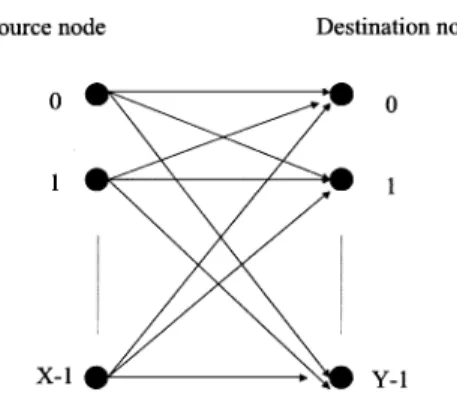
Fig. 17. Interconnection-wire model.
large. In this situation, a large number of crosspoints is pro-duced. That causes high layout complexity. When we implement the dispatching scheduler in one chip, the layout complexity af-fects the interconnection between transistors. However, if we cannot implement it in one chip due to a gate limitation, we need to use multiple chips. In this case, the layout complexity influ-ences not only the interconnection within a chip, but also the in-terconnection between chips on printed circuit boards (PCBs). In addition, the number of pins in the scheduler chips of CRRD increases.
Consider that there are source nodes and destination nodes. We assume that each source node is connected to all the destination nodes with wires without detouring, as shown in Fig. 17. The number of crosspoints for the interconnection wires between nodes is given by
(14) The derivation of (14) is described in Appendix E. Let the number of crosspoints for interconnection wires between
VOQs and output-link arbiters be .
is determined by
(15) Note that the factor of three in (15) expresses the number of groups of wires, as described at the beginning of Sec-tion VII-C-I.
2) CMSD: In CMSD, each VOQ arbiter is connected to its own slave output-link arbiters with three groups of wires. The first group is used by a VOQ arbiter to send requests to the slave output-link arbiters. The second one is used by a VOQ arbiter to receive grants from the slave output-link arbiters. The third one is used by a VOQ arbiter to send grants to the slave output-link arbiters.
In the same way, each VOQ group is connected to all the master output-link arbiters with three groups of wires. The first is used by a VOQ group to send requests to the master output-link arbiters. The second is used by a VOQ group to receive grants from the master output-link arbiters. The third is used by a VOQ group to send grants to the master output-link arbiters.
Let the number of crosspoints for interconnection wires
be-tween arbiters in CMSD be . is
de-termined by
(16)
The first term on the right-hand side is the number of cross-points of the interconnection wires between VOQs and slave output-link arbiters in VOQ groups. The second term is the number of crosspoints of the interconnection wires between
VOQ groups and master output-link arbiters.
3) Comparison of : As the switch size
in-creases, is much larger than . In
gen-eral, when ,
. For example, when and , the number
of crosspoints of the interconnection wires of CMSD is reduced by 87.5%, 93.8%, and 96.9%, respectively, compared with that of CRRD. Thus, CMSD can dramatically reduce the number of wire crosspoints.
VIII. CONCLUSIONS
A Clos-network switch architecture is attractive because of its scalability. Unfortunately, previously proposed implementable dispatching schemes are not able to achieve high throughput unless the internal bandwidth is expanded.
First, we have introduced a novel dispatching scheme called CRRD for the Clos-network switch. CRRD provides high switch throughput without increasing internal bandwidth, while only simple round-robin arbiters are employed. Our simulation showed that CRRD achieves 100% throughput under uniform traffic. Even though the offered load reaches 1.0, the pointers of round-robin arbiters that we use at the IMs and CMs are completely desynchronized and contention is avoided.
Second, we have presented CMSD with hierarchical round-robin arbitration, which was developed as an improved version of CRRD to make it more scalable in terms of dis-patching scheduling time and interconnection complexity in the dispatching scheduler when the size of the switch increases. We showed that CMSD preserves the advantages of CRRD and achieves more than 30% reduction of the dispatching sched-uling time when arbitration time is significant. Furthermore, with CMSD, the number of interconnection crosspoints is
dra-matically reduced with the ratio of . When ,
a 96.9% reduction effect is obtained. This makes CMSD easier to implement than CRRD when the switch size becomes large.
This paper assumes that the dispatching scheduling must be completed within one time slot. However, the constraint is a bottleneck when port speed becomes high. In a future study, based approaches should be considered. A pipeline-based scheduling approach for a crossbar switches is described in [17], which relaxes the scheduling timing constraint without throughput degradation.
APPENDIX I
MAXIMUMSWITCHTHROUGHPUTWITHRD SCHEME UNDERUNIFORMTRAFFIC
To derive (3), we consider the throughput of output link , . This is the same as the switch throughput that we would like to derive because the conditions of all the output links are the same. Therefore,
(17) First, we define several notations. is the prob-ability that one output link in , e.g., , is used by
a ’s request. Here, does not depend on which output link in is used for the request because it is selected randomly. is the probability that the re-quest by wins the contention of output link at
.
By using and , is expressed
in the following equation:
(18) Here, in the last form of (18), we consider that and
do not depend on both and .
Since has VOQs, each VOQ is equally selected by
each output link in . is given by
(19)
Next, we consider . is obtained as follows:
(20) The first term of the right-hand side at (20) is the winning proba-bility of the request by at when there are totally requests for . The second term is the winning proba-bility of the request by at when there are requests at . In the same way, the ( )th term is the
winning probability of the request by at when
there are requests at .
can then be expressed in the following equation:
(21) By using (17)–(19) and (21), we can derive (3).
APPENDIX II
DERIVATION OF FOR
We sketch the term in (3) according to the decreasing order in the following:
(22)
When ,
(23) Therefore,
(24) In the above deduction, we use the following equation:
(25)
APPENDIX III
UPPERBOUND OFMAXIMUMSWITCHTHROUGHPUTWITH RD SHEMEUNDERNONUNIFORMTRAFFIC
The upper bound of the maximum switch throughput with RD scheme under nonuniform traffic is determined by (26), shown at the bottom of the page.
Equation (26) can be easily derived in the same way as (3). However, since the traffic load of each VOQ is different, (3) has
Fig. 18. Comparison between simulation and analytical upper bound results under nonuniform traffic (n = m = k = 8).
to be modified. The first term of the right-hand side at (26) is ob-tained by considering the probability that a heavy-loaded VOQ sends a request to the CM and wins the contention. The second term of the right-hand side is obtained by considering the prob-ability that, when a heavy-loaded VOQ and nonheavy-loaded VOQs send a request to the CM, a nonheavy-loaded VOQ wins the contention. The third term of the right-hand side is obtained by considering the probability that a heavy-loaded VOQ does not send a request to the CM, nonheavy-loaded VOQs send re-quests to the CM, and a nonheavy-loaded VOQ wins the con-tention.
Note that (26) gives the upper bound of the switch throughput of the RD scheme in the switch model described in Section II. This is because only one cell can be read from the same VOQ at the same time slot in the switch model, as described in Sec-tion II. However, we assume that more than one cell can be read from the same VOQ at the same time slot in the derivation of (26) for simplicity. This different assumption causes different results under nonuniform traffic.14
Fig. 18 compares the simulation result with the upper bound result obtained by (26). As increases to approximately 0.6, the difference between the simulation and analytical results in-creases due to the reason described above. At the region of , the difference decreases with because the contention probability at the CM decreases.
APPENDIX IV
TIMECOMPLEXITY OFROUND-ROBINARBITER In a round-robin arbiter, the arbitration time complexity is dominated by an -to- priority encoder, where is the number of inputs for the arbiter.
The priority encoder is analogous to a maximum or minimum search algorithm. We use a binary search tree, whose computa-tion complexity (and, thus, the timing) is , where is the depth of the tree, and where is equal to for a binary tree.
The priority encoder, in the canonical form, has two stages: theAND-gate stage and theOR-gate stage. In theAND-gate stage,
14However, under uniform traffic, both results are exactly the same because
all the VOQs can be assumed to be in a nonempty state. This does not cause any difference in the results.
there are ANDgates where the largest gate has inputs. An -inputANDgate can be built by using a number of -inputAND gates where the level of delay is , i.e., in . As for theOR-gate stage, there are ORgates where the largest has inputs. The largest ANDgate delay is then the delay order for the priority encoder.
APPENDIX V DERIVATION OF(14)
We define an interconnection wire between source node ,
where and destination node , where
, as . We also define the number of crosspoints
that wire has as .
The total number of crosspoints of the interconnection wires between source nodes and destination nodes is ex-pressed by
(27)
Here, the factor of 1/2 on the right-hand side of (27) eliminates the double counting of the number of crosspoints.
First consider . Since has no crosspoints
with other wires, . Since has
crosspoints with ,
. has
crosspoints with ,
. Therefore,
. In the same way, .
Next, consider . Since has
crosspoints with ,
. has crosspoints with
and
cross-points with . Therefore,
. has
crosspoints with ,
and
cross-points with . Therefore,
. In the same way, .
We can then derive the following:
In general, is given by
(28) We substitute (28) into (27). The following equation is obtained:
REFERENCES
[1] T. Anderson, S. Owicki, J. Saxe, and C. Thacker, “High speed switch scheduling for local area networks,” ACM Trans. Comput. Syst., vol. 11, no. 4, pp. 319–352, Nov. 1993.
[2] T. Chaney, J. A. Fingerhut, M. Flucke, and J. S. Turner, “Design of a Gigabit ATM switch,” in Proc. IEEE INFOCOM, Apr. 1997, pp. 2–11. [3] H. J. Chao, B.-S. Choe, J.-S. Park, and N. Uzun, “Design and
imple-mentation of Abacus switch: A scalable multicast ATM switch,” IEEE
J. Select. Areas Commun., vol. 15, pp. 830–843, June 1997.
[4] H. J. Chao and J.-S. Park, “Centralized contention resolution schemes for a large-capacity optical ATM switch,” in Proc. IEEE ATM Workshop, Fairfax, VA, May 1998, pp. 11–16.
[5] H. J. Chao, “Saturn: A terabit packet switch using Dual Round-Robin,” in Proc. IEEE Globecom, Dec. 2000, pp. 487–495.
[6] F. M. Chiussi, J. G. Kneuer, and V. P. Kumar, “Low-cost scalable switching solutions for broadband networking: The ATLANTA archi-tecture and chipset,” IEEE Commun. Mag., pp. 44–53, Dec. 1997. [7] C. Clos, “A study of nonblocking switching networks,” Bell Syst. Tech.
J., pp. 406–424, Mar. 1953.
[8] T. H. Cormen, C. E. Leiserson, and R. L. Rivest, Introduction to
Algo-rithms, 19 ed. Cambridge, MA: MIT Press, 1997, sec. 13.2, p. 246. [9] C. Y. Lee and A. Y. Qruc, “A fast parallel algorithm for routing unicast
assignments in Benes networks,” IEEE Trans. Parallel Distrib. Syst., vol. 6, pp. 329–333, Mar. 1995.
[10] T. T. Lee and S.-Y. Liew, “Parallel routing algorithm in Benes-Clos net-works,” in Proc. IEEE INFOCOM, 1996, pp. 279–286.
[11] N. McKeown, “Scheduling algorithm for input-queued cell switches,” Ph.D. dissertation, Dept. Elect. Eng. Comput. Sci., Univ. California at Berkeley, Berkeley, CA, 1995.
[12] N. McKeown, V. Anantharam, and J. Walrand, “Achieving 100% throughput in an input-queued switch,” in Proc. IEEE INFOCOM, 1996, pp. 296–302.
[13] N. McKeown, M. Izzard, A. Mekkittikul, W. Ellerisick, and M. Horowitz, “Tiny-Tera: A packet switch core,” IEEE Micro, pp. 26–33, Jan.–Feb. 1997.
[14] N. McKeown, “The iSLIP scheduling algorithm for input-queues switches,” IEEE/ACM Trans. Networking, vol. 7, pp. 188–200, Apr. 1999.
[15] A. Mekkittikul and N. McKeown, “A practical scheduling algorithm to achieve 100% throughput in input-queued switches,” in Proc. IEEE
IN-FOCOM, 1998, pp. 792–799.
[16] E. Oki, N. Yamanaka, Y. Ohtomo, K. Okazaki, and R. Kawano, “A 10-Gb/s (1.25 Gb/s2 8) 4 22 0.25-m CMOS/SIMOX ATM switch based on scalable distributed arbitration,” IEEE J. Solid-State Circuits, vol. 34, pp. 1921–1934, Dec. 1999.
[17] E. Oki, R. Rojas-Cessa, and H. J. Chao, “A pipeline-based approach for maximal-sized matching scheduling in input-buffered switches,” IEEE
Commun. Lett., vol. 5, pp. 263–265, June 2001.
[18] J. Turner and N. Yamanaka, “Architectural choices in large scale ATM switches,” IEICE Trans. Commun., vol. E81-B, no. 2, pp. 120–137, Feb. 1998.
Eiji Oki (M’95) received the B.E. and M.E. degrees in instrumentation engineering and the Ph.D. degree in electrical engineering from Keio University, Yoko-hama, Japan, in 1991, 1993, and 1999, respectively.
In 1993, he joined the Communication Switching Laboratories, Nippon Telegraph and Telephone Corporation (NTT), Tokyo, Japan, where he has researched multimedia-communication network ar-chitectures based on ATM techniques, traffic-control methods, and high-speed switching systems with the NTT Network Service Systems Laboratories. From 2000 to 2001, he was a Visiting Scholar with Polytechnic University of New York, Brooklyn. He is currently engaged in research and development of high-speed optical IP backbone networks as a Research Engineer with NTT Network Innovation Laboratories, Tokyo, Japan. He coauthored Broadband
Packet Switching Technologies (New York: Wiley, 2001).
Dr. Oki is a member of the Institute of Electrical, Information and Commu-nication Engineers (IEICE), Japan. He was the recipient of the 1998 Switching System Research Award and the 1999 Excellent Paper Award presented by IEICE, Japan, and the IEEE ComSoc. 2001 APB Outstanding Young Researcher Award.
Zhigang Jing (M’01) received the B.S., M.S., and Ph.D. degrees in optical fiber communication from the University of Electronic Science and Technology of China, Chengdu, China, in 1993, 1996, and 1999, respectively, all in electrical engineering.
He then joined the Department of Electrical Engineering, Tsinghua University, Beijing, China, where he was a Post-Doctoral Fellow. Since March 2000, he has been with the Department of Electrical Engineering, Polytechnic University of New York, Brooklyn, as a Post-Doctoral Fellow. His current research interests are high-speed networks, terabit IP routers, multimedia communication, Internet QoS, Diffserv, MPLS, etc.
Roberto Rojas-Cessa (S’97–M’01) received the B.S. degree in electronic instrumentation from the Universidad Veracruzana (University of Veracruz), Veracruz, Mexico, in 1991. He graduated with an Honorary Diploma. He received the M.S. degree in electrical engineering from the Centro de In-vestigacion y de Estudios Avanzados del Instituto Politecnico Nacional (CINVESTAV-IPN), Mexico City, Mexico, in 1995, and the M.S. degree in computer engineering and Ph.D. degree in electrical engineering from the Polytechnic University of New York, Brooklyn, in 2000 and 2001, respectively.
In 1993, he was with the Sapporo Electronics Center in Japan for a Micro-electronics Certification. From 1994 to 1996, he was with UNITEC and Iber-chip, Mexico City, Mexico. From 1996 to 2001, he was a Teaching and Re-search Fellow with the Polytechnic University of Brooklyn. In 2001, he was a Post-Doctoral Fellow with the Department of Electrical and Computer Engi-neering, Polytechnic University of Brooklyn. He has been involved in applica-tion-specific integrated-circuit (ASIC) design for biomedical applications and research on scheduling schemes for high-speed packet switches and switch reli-ability. He is currently an Assistant Professor with the Department of Electrical and Computer Engineering, New Jersey Institute of Technology, Newark. His research interests include high-speed and high-performance switching, fault tol-erance, and implementable scheduling algorithms for packet switches.
Dr. Rojas-Cessa is a member of the Institute of Electrical, Information and Communication Engineers (IEICE), Japan. He was a CONACYT Fellow.
H. Jonathan Chao (S’83–M’85–SM’95–F’01) received the B.S. and M.S. degrees in electrical engineering from the National Chiao Tung Univer-sity, Taiwan, R.O.C., respectively, and the Ph.D. in electrical engineering from The Ohio State University, Columbus.
In January 1992, he joined the Polytechnic Univer-sity of New York, Brooklyn, where he is currently a Professor of electrical engineering. He has served as a consultant for various companies such as NEC, Lu-cent Technologies, and Telcordia in the areas of ATM switches, packet scheduling, and MPLS traffic engineering. He has given short courses to industry in the subjects of the IP/ATM/SONET network for over a decade. He was cofounder and from 2000 to 2001, the CTO of Coree Networks, where he led a team in the implementation of a multiterabit packet switch system with carrier-class reliability. From 1985 to 1992, he was a Member of Technical Staff with Telcordia, where he was involved in transport and switching system architecture designs and ASIC implementations, such as the first SONET-like framer chip, ATM layer chip, aequencer chip (the first chip handling packet scheduling), and ATM switch chip. From 1977 to 1981, he was a Senior En-gineer with Telecommunication Laboratories, Taiwan, R.O.C., where he was involved with circuit designs for a digital telephone switching system. He has authored or coauthored over 100 journal and conference papers. He coauthored
Broadband Packet Switching Technologies (New York: Wiley, 2001) and Quality of Service Control in High-Speed Networks (New York: Wiley, 2001). He has
performed research in the areas of terabit packet switches/routers and QoS con-trol in IP/ATM/MPLS networks. He holds 19 patents with five pending.
Dr. Chao served as a guest editor for the IEEE JOURNAL ONSELECTEDAREAS INCOMMUNICATIONSwith special topic on “Advances in ATM Switching Sys-tems for B-ISDN” (June 1997) and “Next Generation IP Switches and Routers” (June 1999). He also served as an editor for the IEEE/ACM TRANSACTIONS ON
NETWORKING(1997–2000). He was the recipient of the 1987 Telcordia Excel-lence Award. He was a corecipient of the 2001 Best Paper Award of the IEEE TRANSACTIONS ONCIRCUITS ANDSYSTEMS FORVIDEOTECHNOLOGY.