TECHNICAL UNIVERSITY OF CLUJ-NAPOCA
ACTA TECHNICA NAPOCENSIS
Series: Applied Mathematics, Mechanics, and Engineering Vol. 60, Issue II, June, 2017
THE DESIGN OF A PLASTIC INJECTION MOLD FOR THE PART
“TENSILE TEST SPECIMEN”
Camelia MORAR, Adrian POPESCU
Abstract: This paper presents the process of manufacturing an injection mold, starting with the design of the part, the design for the cavity plate, followed by the simulation of the injection molding process and the establishment of the manufacturing process. Our aim was to design a mold for the injection of tensile test specimens made from polyamide 6.6. In order to achieve this, after the dimensioning of the mold cavity, we created three design solutions in the Solid Works software and simulated the injection molding process for them using the Simulation Mold Flow software, after which we made the simulation for the manufacturing of the cavity plates using the Solid CAM software. After conducting all the simulations, we were able to find the best solution for the design of the injection mold.
Key words: plastic injection, injection mold, polyamide, molding process, mold design.
1. INTRODUCTION
Injection molding is a manufacturing process, widely used for manufacturing a variety of parts, starting from micro-components to entire body panels of cars. Parts to be injected must be very carefully designed to facilitate the injection process. The material used for the part, the desired shape and features of the part, the material of the mold, and the properties of the molding machine must all be taken into account.
The versatility of injection molding is facilitated by this breadth of design considerations and possibilities. In this paper, the main task is to find the best design for a plastic injection mold with several molds cavities, to achieve the desired shape and accuracy for the part “tensile test specimen”. Finding the best solution involves issues from the economical, technological and design fields. A mold designed and adjusted correctly must work properly to ensure the volume of parts required per unit of time, and to be cheap. Also, the produced parts must be accurate, without flaws in the material structure.
The issue of designing the plastic materials injection molds involves a number of factors that need to be taken into account. These factors must be complied particularly when it comes at the processing and the dimensioning of the injection molds cavities. In order to be efficient in designing, but, in the same time to be able to take into account the economical side, we must have an efficient design strategy. This issue has been approached by other researchers in their works [1], [2], [3], [4], [5]. The Solid Works 3D computer-aided design (CAD) software delivers powerful design functionality, and it made it possible for us to design several multi-cavity plates in order to find the best solution for the manufacturing of the mold. For the dimensioning of the molds cavities, it’s important to take in consideration the properties of the material (in this case polyamide 6.6) and the characteristics of the plastic injection machine.
injection pressure and the confidence of fill for each plate [8], [9].
By using this method of simulation for the process we found an estimation of the manufacturing time and also the weak points of our designs, so we know where and what we should modify before we invest anything in tooling.
To calculate the manufacturing time and the costs in order to produce the cavity plates, we used computer-aided manufacturing (CAM) software called Solid Cam.
Finally, one of the cavity plates designs was chosen and we designed the rest of the injection mold components and realized the assembly.
2. ANALYTICAL RESULTS AND SIMULATIONS
In order to obtain the correct dimensions for the part, the first thing we needed to do was to make the dimensioning calculations of the molds cavities in which the plastic will be injected, considering the material shrinkage (0,6-3%) and density (1,14 g/cm3), as well as the injection machine characteristics (Wittmann EcoPower 240).
The dimensioning of the cavity, as well as the dimensioning and choosing of the injection system has a decisive influence on the quality and productivity of the injected parts and the manufacturing process [6], [7].
The parts to be injected are the tensile test specimens, made according to SR EN ISO 527 – 2000, Figure 1.
Fig. 1. Tensile test specimens according to
SR EN ISO 527-200, E=115±5[mm]
The calculated dimensions of the molds cavities for the tolerated dimensions of the test specimen are presented in Table 1.
Table 1
Calculated dimensions of the molds cavities.
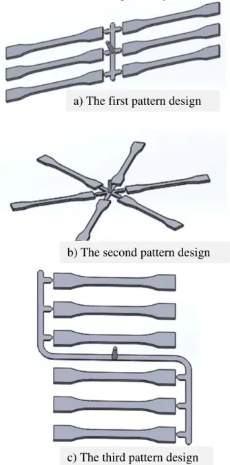
After the dimensioning of the molds cavities and the calculation of their number (depending on the injection machine capacity of 67 g/s), we designed three patterns for the distributions of the molds cavities on the plate, Figure 2.
Fig. 2. Molds cavities patterns and the injection network Dimension of the test
specimen [mm]
Calculated dimension of the cavity [mm] Φ10 ± 0,2
Φ20 ± 0,2
Φ50 ± 0,2
Φ60 ± 0,5
Φ115 ± 1
a) The first pattern design
b) The second pattern design
Once we obtained the three forms resulting from the injection, we imported them all Autodesk Simulation Mold Flow software. Under the program, we first analyzed the part to eliminate potential design flaws, and then we oriented the abutment’s axis parallel with the Z axis. Then we choose the injection point and the type of material injected. After the choice of material, we have to set the melting temperature of the plastic and the mold temperature. Therefore, for the material PA 6.6, we obtained the melting point of about 301 °C and mold temperature of about 71 °C. After choosing all these parameters we could start the proper analysis of material flow (rheological simulation), called Fill analysis. The analysis offers us a series of results, but the most important for the productivity of the process, if other results are acceptable, are the fill time of the molds cavities time and the cooling time to reach the ejection temperature.
The cooling time is calculated in the analysis for the case where the mold does not have cooling channels which help to speed up the process.
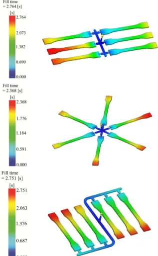
You can see in Figure 3 the fill time results from the rheological simulation for all three designs of the injection network. It is easy to observe that the third design of the injection pattern has the most uniform filling and the first one does not have a correct filling, which may result in pieces (test specimens) with internal stresses. These stresses, when released, lead to
warping. Warping is usually caused by non-uniform cooling of the mold material.
Different cooling rates in different parts of the mold cause the plastic to cool differently and thus create internal stresses.
Fig. 3. The filling time for the all three designs of the
injection network
The main results for all three designs can be seen in the Table 2.
Table 2
Main results of the rheological simulation from the Mold Flow software.
The model The results
The first design pattern
The second design pattern
The third design pattern
Fill time [s] 2,764 2,368 2,751
Time to reach ejection temperature [s] 18,51 17,03 17,35
Confidence of fill [%] 100 100 100
Quality prediction [%] 96,3 98,4 99,3
Injection pressure [MPa] 59,65 91,91 90,83
Pressure drop [MPa] 59,65 91,91 90,83
Temperature at flow front [°C] 300,1 304,0 304,5
Average temperature [°C] 309.9 309.9 310,3
Temperature variance [°C] 4,521 6,611 4,5
Cooling time variance [s] 13,76 4,166 5,155
Total part weight [g] 61,94 61,38 71,93
Shot volume [cm3] 55,305 54,807 64,22
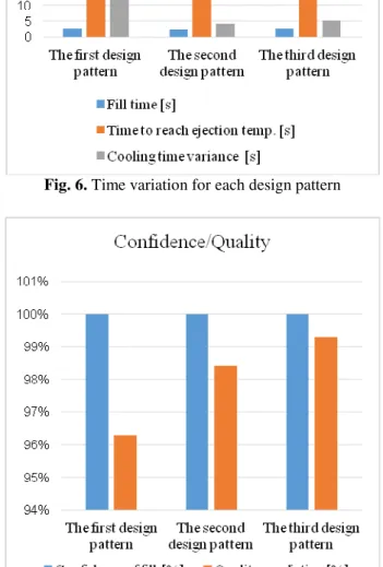
The significant values presented in the table 2 have been graphically represented in the figures 4, 5, 6 and 7. Figure 4 highlights the injection temperature variation for each mold model, and figure 5 shows the injection pressures values.
Figures 6 and 7 have shown the variation of the parameters that take into quality of the filling of the molds cavities and the filling time, respectively the cooling time needed till the extraction of the parts from the mold.
The time needed for the cooling of the parts obtained through injection has a pretty big impact upon the economical factor. This issue was been treated even by Marian B. [10], [11].
Fig. 4. Temperature variation for each design pattern
Fig. 5 Injection pressure variation for each design pattern
The information presented above helps us in choosing the optimal injection mold design from the economical point of view and also from the point of view of the technological process parameters.
When we are designing an injection mold, a number of simulations must be done. They allow the highlighting of the filling of the molds cavities, its quality and also the time needed till the extraction of the parts from the mold.
Fig. 6. Time variation for each design pattern
Fig. 7. Quality prediction for each design pattern
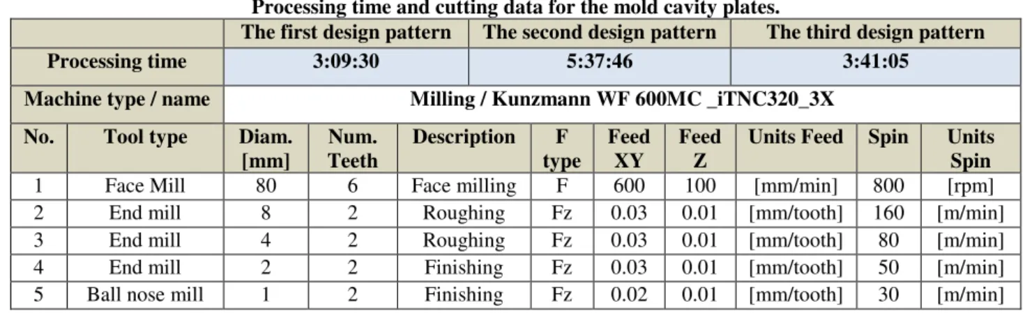
It is preferable that, design of the mold to allow the achieving the greatest possible number of parts in one injection cycle, but, in the same time, the dimensions of the mold to be as minimized as possible and the extraction of the parts after injection to be as easy to achieve. In order to simulate the manufacturing process of the plates we used the Solid CAM software.
We considered that the manufacturing is carried out in three-axis milling machine
Kunzmann-WF 600MC _iTNC320_3X.
The cutting data and the resulted time of the simulation can be seen in Table 3.
Table 3
Processing time and cutting data for the mold cavity plates.
The first design pattern The second design pattern The third design pattern
Processing time 3:09:30 5:37:46 3:41:05
Machine type / name Milling / Kunzmann WF 600MC _iTNC320_3X
No. Tool type Diam. [mm]
Num. Teeth
Description F type
Feed XY
Feed Z
Units Feed Spin Units Spin
1 Face Mill 80 6 Face milling F 600 100 [mm/min] 800 [rpm]
2 End mill 8 2 Roughing Fz 0.03 0.01 [mm/tooth] 160 [m/min]
3 End mill 4 2 Roughing Fz 0.03 0.01 [mm/tooth] 80 [m/min]
4 End mill 2 2 Finishing Fz 0.03 0.01 [mm/tooth] 50 [m/min]
5 Ball nose mill 1 2 Finishing Fz 0.02 0.01 [mm/tooth] 30 [m/min]
We choosen the third option of the cavity plates design for designing the entire mold because it has the most uniform injection, the fabrication time is shorter and volume of the plate is lower compared to the other plates, consequently the mold will be easier and cheaper. The final step was the designing of the mold, using Solid Works software. The designing of the mold was made by taking into account the technological, functional and economical factors.
3. CONCLUSIONS
The injection process, on one hand, must meet the requirements for the quality of the parts, and on the other hand, it needs to shorten the injection cycle time to reduce the cost of manufacture. It is very important to make these analyzes and simulations before executing the mold because one mistake can lead to it’s rejection, which means lost time and high costs. By knowing the best solutions used in the manufacturing practice and by continuous improvement of the designing for injection molds, the molds are conceived with superior performances.
To find the best option for designing the cavity plates, we designed three variants with different molds cavities settlements. For the three types we performed an analysis of the filling, to determine the injection time and cooling time of the injected parts. With the help
of the simulation we found that one of the designed plates does not have a correct filling, which can lead to warpage of the test specimens. Then, for each of the three variants we have simulated the manufacturing process using Solid CAM software and determined the fabrication time. Using all the data from the simulations, we could choose the best plate for injection and to design the mold.
4. REFERENCES
[1] Popan I.A., Popan A., Cosma S.C., Carean A..Analyses of process parameters influence on the drilling process by using carbide drills for steel ST52-3, International
Conference on Computing and Solutions in Manufacturing Engineering - CoSME'16, published in MATEC Web of Conferences 94, 02011, 2017, doi: 10.1051/matecconf/20179402011, Brasov, 2017.
[2] Popan I.A., Balc N., Luca B., Popan A..
CNC machining of the complex copper electrodes, Acta Universitatis Cibiniensis –
Technical Series, Vol. LXVI, DOI: 10.1515/aucts-2015-0045, Sibiu, 2015. [3] Panc N., Bocăneţ V., Bulgaru M., Beldean
C.. Research on holes finishing operations performance by cutting, Acta Technica
[4] Panc N., Vuscan I., Bâlc N.. Research on the deformations caused by the manufacturing devices onto the parts with low rigidity, Academic Journal of
Manufacturing Engineering, ISSN 1583-7904, Vol 11, Issue 4, 2013.
[5] Beldean C., Vuşcan I., Panc N., Mărieş M.. Trapezoidal threading cycle for numerical controlled lathes, Acta Technica
Napocensis, Series: Applied Mathematics and Mechanics, ISSN 1221-5872, Vol 57, Issue 1, Cluj-Napoca, 2014.
[6] David O. K.. Injection Mold Design Engineering (Second Edition), Carl Hanser
Verlag, ISBN: 978-1-56990-570-8, Munich, 2015.
[7] Peter K., Rong Z.. Flow Analysis of Injection Molds, Hanser Publications 6915
Valley Avenue, ISBN 978-1-56990-512-8, München, Germany, 2013.
[8] Katharina A., Erwin B., Hans J. E., Ralf G., Nina G., Martin K., Marco N., Tim O., Philip S., Sandro W., Karl W., Jörg M..
Measuring fibre orientation in sisal
fiber-reinforced, injection molded polypropylene – Pros and cons of the experimental methods to validate injection molding simulation,
Composites: Part A 95, pg. 56-64, 2017. [9] Sun X., Lasecki J., Zeng D., Gan Y., Su X.,
Tao J.. Measurement and quantitative analysis of fiber orientation distribution in long fiber reinforced part by injection molding, Polym Test 42 pg.168–74, 2015.
[10] Bútora, P., Náplava, A., Ridzoň, M., Jozef
Bílik, J., Tittel, V.. Particle Filled Polyethylene Composites Used In The Technology Of Rotational Moulding,
Research Papers, Faculty Of Materials Science And Technology In Trnava, Slovak University Of Technology In Bratislava, 10.2478/v10186-011-0051-5 2011, Volume 19, Number 31, Trnava, 2011.
[11] Blaško, M., Tittel, V., Ridzoň M.. Cae Analysis Of Conformal Cooling Application – Case Study, International Journal of
Engineering, Tome X, Fascicule 3, ISSN-1584-2673, Slovakia, 2012.
PROIECTAREA UNEI MATRIŢE DE INJECTAT PENTRU REPERUL “EPRUVETA PENTRU INCERCAREA LA TRACŢIUNE”
Rezumat: Lucrarea de față abordează probleme de cercetare și modernizare a proiectării matrițelor de injectat
materiale plastice. Ea prezintă întregul proces de fabricație a unei matrițe de injectat materiale plastice, începând cu
proiectarea piesei și calcularea dimensiunilor cuiburilor, urmate de simularea procesului de injectare și stabilirea
procesului de fabricație. Scopul a fost realizarea unei matrițe de injectare adecvată pentru obținerea unor epruvete
pentru încercarea la tracțiune din poliamidă 6.6. Găsirea celei mai bune soluții de proiectare implică aspecte de natură
economică, tehnologicăși constructivă. O matriță proiectată și reglată corect trebuie să funcționeze bine, să asigure
volumul de piese în unitatea de timp impusă, și să fie cât mai ieftină. De asemenea, piesele obținute trebuie să fie
precise, fără defecte în structura materialului. În acest sens, după efectuarea calculelor de dimensionare, am proiectat
trei variante constructive diferite ale plăcilor de formare cu ajutorul programului Solid Works și am simulat procesul de
injectare al materialului (analiza reologică) utilizând programul Simulation Mold Flow, după care am simulat procesul
de fabricație cu programul Solid Cam. Folosind toate aceste date și simulări, am reușit să alegem cea mai bună formă
constructivă pentru a proiecta matrița.
Camelia MORAR, Student, Technical University of Cluj-Napoca, Department of Manufacturing
Engineering, [email protected].
Adrian POPESCU, Lecturer, PhD, Technical University of Cluj-Napoca, Department of