TECHNICAL UNIVERSITY OF CLUJ-NAPOCA
ACTA TECHNICA NAPOCENSIS
Series: Applied Mathematics, Mechanics, and Engineering Vol. 59, Issue II, June, 2016
STUDIES REGARDING THE VIBRATION TABLE
AND DUMPING THEIR
Aurora Felicia CRISTEA, Cosmin DEAC
Abstract: The paper’s study presents simplistic one of the most common elements used in the depreciation of industrial equipment (rubber). This study involves the mathematical model and the advantages or disadvantages to using this material. It also, deals with the problem of the source of the vibration generators, namely vibrant table "MEVI", by calculation, choosing the number of vibration generators, force generators and obtained as a result of their vibrations.
Key words: vibrant table, rubber, vibration generator.
1. INTRODUCTION
1.1. Generality
Vibrating tables [6] can be used in various industrial applications, in order to achieve compaction, sorting materials, emptying and filling of containers etc.
Vibrating tables will design according to their destination. The principle of operation of these tables consists of inducing vibrations in a metal countertop that is isolated through elastic elements, the fixed part of the meal (its support).
Basics of concrete apparently executed, you can compact equipment for on the exciter. Vibrant table's power will be correlated with the weight of the printing element assembly.
Vibrations [1], [2] may induce by fitting metal countertop has one or more electric or hydraulic vibrators. Centrifugal force to them you can adjust by changing hexcentric position vibrators. Low vibration frequency can be 5-15 Hz or high frequency over 100 kHz.
Table can be fitted with restraint systems or containers of forms, which are used in the production process.
2. VIBRATING MACHINES
MONOMASICE, OPERATED WITH VIBRATION GENERATORS
INCLUDING THE UNBALANCED MASSES
Vibrating mono-masses machines can be designed as conveyors, vibratory separators, sieves, vibrating tables etc. [6]. Such a machine can be mono-masses by a generator vibration rigid mounted on the body of work. Vibration generator with unbalanced masses is trained by an electric motor, mounted on the machine are placed. For this purpose, the most used are generators of vibration unbalanced flywheel static or eccentric. The working body is mounted on the frame use only by means of elastic links. Elastic elements springs can be used with linear and non-linear characteristic [3].
2.1. Mathematical model of “MEVI” table
to generate a harmonic force of inertia after the normal direction at the leaf springs.
Because the vibration amplitude of these machines is relatively small (1-8 mm) may consider it as the model for calculating simple oscillator, damped [6].
Mathematical model from Figure 1 is identified in simplified form, with vibrant, table model, MEVI "got into the study in this project. In Figure 1 is shown schematically this type car, where vibration generator will need to generate a harmonic force of inertia after the normal direction at the leaf springs.
Because the vibration amplitude of these machines is relatively small (1-8 mm) may consider it as the model for calculating simple oscillator, damped [6].
Mathematical model from Figure 1 is identified in simplified form, with vibrant, table model, MEVI "got into the study in this paper.
Fig. 1 Vibrating board (table) with the vibrating
generator surse [6].
To determine the strength of vibration generators, shall be considered as the study on the vibrating table simplify only from one direction, reported to a fixed reference system namely Ox axis.
Differential equation of motion of the body after the direction normal to the Ox, the leaf springs is [6]:
(
m+m0)
&x&+cx&+kx=F0cosωt (1) where, F0 =m0rω2 (2) and Fo [N] – harmonically excitation force duethe vibration generator source;
• M, mo [kg] – engine mass, respectively,
causing unbalanced mass production of vibrations;
•
ω
- angular velocity [rad/s] - dependent-engine revolution n [RPM] and where ; • r - the radius of the pallet (mm) engines; • x [m] and its derivatives of order one and two, respectively, velocity and acceleration vibration due to the table after the direction of the Ox;where:
- m0 = 3 kg, counterweight;
- m = 800 – 2000 kg, vibrant table load; - r = e [m], generator eccentricity; - F0[N] – disruptive force;
- f – in this case the f symbolizes the frequency 50-250 Hz
- angular velocity ω = 314 rad/s (f = 250 Hz) and 15 000 rad/s (f = 250 Hz);
- generator rotation n = 100 RPM (f = 50 Hz) and n = 15 000 RPM (f = 250 Hz).
Relation (1) becomes:
t m m F p x n
x 2 cosω
0 0 2 + = + + & &
& (3)
notated:
(
)
,2m m0 c n + = 0 m m k p +
= (4)
- p – system oscillation [s-1];
Stationary solution of equation (3) is:
x=xacos
(
ωt−ϕ)
(5)(
)
(
)
2 0
2
2 2 2 2
0 , 4 a m r x
m m p n
ω ω ω = + − + 2 2 2 ω ω ϕ − = p n
tg (6)
• – undimensional unit and
named fraction of the critical dumping ccr. where: φ – phase [rad];
( )
[
]
(
2)
2 2 2 2 2 2 2 4 1 1 1 4 γ ζ γ ε γ γ ζ + − + − + =f (7)
(
)
[
2](
2)
2 2 3 1 1 1 4 2 γ γ ε γ ζ εζγ ϕ − − + + =
tg (8)
where f (γ) [mm] – vibration amplitude function of 2 1 1 2 γ ζ = − ;
t x r m
M =− 0 &&sinω (9)
Fig. 2 P perturbation force of the generator source [6].
The maximum and minimum values of the engine moment M, notated the Mmin [Nm], in
accordance with the relationship (9) are: where f and fm-dimensionless factor characterized by
disruptive force transmissibility.
M =M0
(
fm + fa)
,(
fm fa)
M
Mmin = 0 − . (10)
Reaction force of the oscillation bearing notated the P1 [N] to the stationary moving is
[6]:
(
)
− + +=F t
Pl ω
γ γ ζ ϕ εγ cos 1 4 cos 1 2 2 2 2 2
0 (11)
Durable work performed in a cycle, due to
frictional forces from the camps is [6]:
L
(
)
[
]
− + − += 2 2 2 2
2 2 0 ) 1 ( 4 1 2 1 2 γ γ ζ π γ εγ
πrFs (12)
where D [mm] is the bearing diameter
µ – friction coefficient of the bearing
(undimensional) and r D s 2 = .
The instantaneous power expression is:
(
)
[
ω ϕ]
ω
ω= + +
=M M f f t
N 0 m 0sin2 (13)
The medium power is:
(
2)
2 2 23 2
0
4
1 γ ζ γ
εζγ ω
+ − =rF
Nm (14)
Power consumed in the bearing is:
(
)
(
)
− + − + = = 2 2 2 2 2 2 0 1 4 1 2 12 π ζ γ γ
γ εγ ω µ π ω F r s L
Nl (15)
The medium power use of the engine is:
(
)
(
(
)
)
− + − + + + − = 2 2 2 2 2 2 2 2 2 2 3 3 2 1 1 2 1 41 π ζ γ γ
γ εγ µ γ ζ γ εζγ ω s mr
Nm (16)
It is noted that the average power is proportional to the square of the amplitude and represents a maximum field of resonance.
Advantages: in all these relations it could see that the material is an excellent rubber silencer. The speed of propagation of sound in the rubber is 45 m/s vs. air-340 m/s, and in steel of 5100 m/s so it is an ideal material to minimize vibrations in equipment vibrant, if you would use other materials for reducing vibrations including noise, as for example the steel arcs they would not soften the noise at rotations of 1000 RPM.
As disadvantage of rubber insulators are under the Act:-atmospheric agents and especially of the various impurities that can reach the rubber (water, oil, acids), it loses its elastic properties. As a result, against such corrosive agents are appropriate measures of protection;
- with time (after 5 ... 20 years), rubber "ages", losing their elastic properties, causing displacement of the Foundation, which can be dangerous and for this reason, machines with long service life, it should be referred to the constructive possibilities of replacing the insulators;
- in terms of calculations, must take account of the fact that the relationship between stresses and deformations is nonlinear, elastic constants and values vary considerably, in relation to the composition of the rubber;
- the rubber spark gaps are not used at temperatures above 70 ... 800C or sub-200 c.
Will this continue some relationships and values concerning the behavior of elastic rubber insulators?
On problems of mechanical rubber requests using Cf form factor, defined as the
ratio between the surface area through which the isolator is loaded and the lateral surface.
2.2. Description of the phenomena
a. In the first phase, the technical characteristics with which I work for selecting the vibration generator, based on the desired vibration amplitudes respectively 1-8 mm. 2 0 F x 2 0 F O x
m && 2
0 x
Hence, using the relations 3,2 for calculation of amplitude and force disruptive, we get the elastic elements which are assumed the status between the vibrant mass "MEVI", respectively vibrating table and are placed, i.e. elements of rubber elastomers:
- rubber studies like d (diameter) x g (thickness) = 10 cm x 8 cm (dimensions for the design of the table: 10 m x 4 m, so it was the need to use a number about 40 pieces of rubber pills status on four rows, at a distance of 1 m in length and 10 pieces in one row.
c - damping coefficient = 20441.01 Ns/m k- coefficient of elasticity N/m = 208,917.6 E- constant longitudinal elasticity =10 MPa.
With relationships (17-18) was calculated coefficient of elasticity and damping rubber, size: function, for all 40 pills of rubber
m N l
ES
k= / =208917,6 / [1]; (18) where: - S the circular surface of the tungsten tip rubber [cm2];
- l-length of circular rubber tungsten tip [cm].
m Ns m
k
c=2 =20441,01 / , [Bra 00] (19)
b. Second step will be calculated and disturbing force F0 magnitude generated by
this at frequencies of 50 Hz and 250 Hz. It said that it takes into account the eccentricity of 0, 5 m and 1.5 m for 3 kg of counterweight at frequencies from 50-250Hz.
As an observation required it is recommended to specify that it is difficult to combine these variables simultaneously, i.e. disruptive force F0, the eccentricity of the
generator, counterweight, so some of the features you need to have vibration generator for "MEVI" proposed for designing all the time, but one or two of the above characteristics will be considered (Table 1).
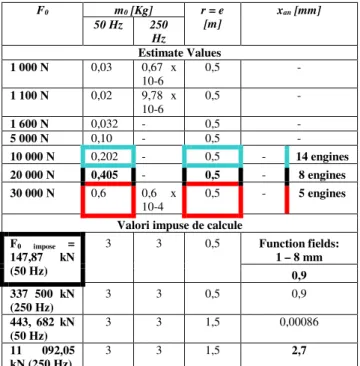
Note: 1. Choosing the type of vibration generator will make the following estimated data calculated in table 1/and juggling with the dimensions r = e, mo, and Fo, so as to obtain
the amplitudes between 1 xan-8 mm.
2. There is no question of the design of this type of generator, since the literature
offers a wide range of such generators, as both and, as well as features like forms, functioning and patterns.
Table 1 Technical characteristics taken into account for the choice of vibration generators and their number, used in the operation of the table "MEVI".
From the calculation of disturbing force F0,
given by the relation (2) shall determine the vibrant table movements "MEVI", calculated from the maximum amount imposed, the loading table vibrant m = 2 000 kg, and at the minimum frequency of 50 Hz, 250 Hz, maximum calculations were performed in Matlab and are rendered graphically in the figures 3-6.
Fig. 3 The velocities and displacements to frequency f = 50 Hz (F0= 147,87 kN).
F0 m0 [Kg] r = e
[m]
xan [mm]
50 Hz 250 Hz
Estimate Values
1 000 N 0,03 0,67 x
10-6
0,5 -
1 100 N 0,02 9,78 x
10-6
0,5 -
1 600 N 0,032 - 0,5 -
5 000 N 0,10 - 0,5 -
10 000 N 0,202 - 0,5 - 14 engines
20 000 N 0,405 - 0,5 - 8 engines
30 000 N 0,6 0,6 x
10-4
0,5 - 5 engines
Valori impuse de calcule F0 impose =
147,87 kN
(50 Hz)
3 3 0,5 Function fields:
1 – 8 mm
0,9 337 500 kN
(250 Hz)
3 3 0,5 0,9
443, 682 kN (50 Hz)
3 3 1,5 0,00086
11 092,05
kN (250 Hz)
Fig. 4 Zoom of the figure 3 – The velocities and displacements to frequency f = 50 Hz (F0 = 147,87 kN].
Fig. 5 The velocities and displacements to frequency f = 250 Hz (F0 = 147,87 kN].
Fig. 6 Zoom of the figure 5 regarding the velocities and displacements to frequency f = 250 Hz
(F0= 147,87 kN].
Figures 3 to 6 represent the speeds and movements for strength of excitation frequencies F0 generated 50 Hz and 250 Hz. If it refers to the movements obtained it appears that they are in the field of 0.003 m, for frequencies studied, i.e. a maximum of 3 mm.
These values are contained within the field of study, if we mean amplitudes of a targeted be obtained respectively from 1-8 mm.
3. CONCLUSIONS
• the necessity of achieving a vibration exciter of large size (w x l = 10 m x 4 m) is a real one, from the need for casting concrete plates, for rapid building of supermarkets.
• for this purpose were addressed in this study:
- the literature study, with types of vibration exciter on the national and international level;
- choosing a type of vibrant mass in terms of the generation of vibrations and determining the number of vibration generators required for expected load.
- The upshot of the study being sizing calculations of resistance, later designing and simulating of vibration table in the study "MEVI".
4. REFERENCES
[1] P. Bratu – Vibraţiile sistemelor mecanice, Editura Tehnică, Bucureşti, 2000, 350 pagini.
[2] P. Bratu – Izolarea şi amortizarea vibraţiilor la utilaje de construcţii, Editura, Incert, Bucureşti 1982, 300 pagini.
[3] Gh. Buzdugan , L. Fetcu , M. Radeş, Vibraţii Mecanice, Editura Didactică şi Pedagogică Bucureşti 1982, 336 pagini. [4] C. Bia, V. Ille, M.V.Soare – Rezistenţa
Materialelor şi Teoria Elasticităţii, Editura Didactică şi Pedagogică, Bucureşti 1983, 936 pagini.
[6] M. Munteanu – Introducere în dinamica maşinilor vibratoare, Editura Academiei Republicii Socialiste România, Bucureşti 1986,307 pagini.
[7] M. Popoviciu , V. Anton , Hidraulică şi maşini hidraulice, Editura Didactică şi Pedagogică, Bucureşti, 1979.
[8] R. Voinea, D. Voiculescu, F. Simion – Introducere în Mecanica Solidului cu Aplicaţii în Inginerie, Editura Arad RSR, 1989, 1151 pagini.
Studii privind mesele vibrante şi amortizarea acestora
Rezumat: Lucrarea tratează la modul simplist unul din cele mai uzuale elemente de amortizare folosite în cazul echipamentelor industriale (cauciuc). Acest studiu implica model matematic si avantaje sau dezavantaje la folosirea acestui material. De asemenea, tratează problema sursei generatoare a echipamentului în vibraţie si anume masa vibrantă „MEVI”, aceasta prin calcul, alegerea numărului de generatoare de vibraţii, respectiv a forţei generatoare şi posibila deplasare de particule obţinută în urma vibrării acestora.
Cuvinte cheie. Masa vibrantă, cauciuc, generator de vibraţii.
CRISTEA Aurora-Felicia, Lector PhD. Dipl. Eng., Technical University of Cluj-Napoca, Mechanical Engineering System Department, no.103-105 B-dul Muncii, Cluj-Napoca, ROMANIA, e-mail: [email protected].
![Fig. 1 Vibrating board (table) with the vibrating generator surse [6].](https://thumb-us.123doks.com/thumbv2/123dok_us/8000219.2121003/2.892.410.787.96.1164/fig-vibrating-board-table-vibrating-generator-surse.webp)
![Fig. 4 Zoom of the figure 3 – The velocities and displacements to frequency f = 50 Hz (F 0 = 147,87 kN]](https://thumb-us.123doks.com/thumbv2/123dok_us/8000219.2121003/5.892.109.451.129.367/fig-zoom-figure-velocities-displacements-frequency-hz-f.webp)
