A multi-objective optimization-based layer-by-layer blade-coating approach for organic solar cells: rational control of
vertical stratification for high performance Journal: Energy & Environmental Science
Manuscript ID EE-ART-07-2019-002295.R1 Article Type: Paper
Date Submitted by the
Author: 20-Aug-2019
Complete List of Authors: Min, Jie; The Institute for Advanced Studies, Wuhan University, Sun, Rui; The Institute for Advanced Studies, Wuhan University, Guo, Jie; Green Catalysis Institute, The College of Chemistry and Molecular Sciences
Wu, Qiang; The Institute for Advanced Studies, Wuhan University Zhang, Zhuohan; Key Laboratory of Soft Chemistry and Functional Materials
Yang, Wenyan; The Institute for Advanced Studies
Guo, Jing; The Insitute for Advanced Studies, Wuhan University Shi, Mumin; The Institute for Advanced Studies
Ye, Long; North Carolina State University, Physics
Jiao, Xuechen ; Monash University, Department of Materials Science and Engineering
Kahmann, Simon; University of Groningen, Zernike Institute for Advanced Materials
Loi, Maria Antonietta; University of Groningen, Zernike Institute for Advanced Materials
Zhang, Yaohong; Faculty of Informatics and Engineering, the University of Electro-Communications
Shen, Qing; Denki Tsushin Daigaku Joho Rikogakubu Joho Rikogaku Kenkyuka, Department of Engineering Science
Ade, Harald; North Carolina State University, Physics
Tang, Weihua; Nanjing University of Science and Technology, Chemical Engineering
Brabec, Christoph; Friedrich-Alexander-Universität Erlangen-Nürnberg, Institute Materials for electronics and energy technology
Photovoltaic performance of solution-processed organic solar cells (OSCs), including
device efficiency and stability, is strongly correlated to the bulk heterojunction (BHJ)
blend microstructure of specific photoactive materials or systems. In these decades, the
BHJ solution processing approach has taken an irreplaceable lead in the development
of OSCs and recently pushed the PCEs to a record high. However, it still has some
drawbacks. Thus, finding an effective and highly repeatable way to control the
morphology is still one of the most important research subjects in OSC field. Based on
this view, we diverted our interest to building optimal morphology with a p-i-n
architecture
via
the layer-by-layer (LbL) blade-coating technique, which is
parsimonious and more easily transferable to a roll-to-roll (R2R) coating environment.
In this contribution, we minutely depicted the intrinsic characteristics of BHJ and LbL
blends during the film formation, and systematically evaluated their multiple target
parameters, including morphological characteristics, optical simulation, physical
kinetics, device efficiency, and blend stability issues. There results highlight that the
LbL approach is more beneficial to reduce the efficiency-stability gap of OSCs and
even a superior alternative to BHJ method in commercial applications.
A multi-objective optimization-based layer-by-layer blade-coating approach for organic solar cells: rational control of vertical stratification for high performance
Rui Sun1, Jie Guo1, Qiang Wu1, Zhuohan Zhang2, Wenyan Yang1, Jing Guo1, Mumin Shi1,
Yaohong Zhang3, Simon Kahmann4, Long Ye5, Xuechen Jiao6, Maria A. Loi4, Qing Shen3,
Harald Ade5, Weihua Tang2, Christoph J. Brabec7, Jie Min1*
1The Institute for Advanced Studies, Wuhan University, Wuhan 430072, China
E-mail: [email protected]
2Key Laboratory of Soft Chemistry and Functional Materials, Ministry of Education, Nanjing
University of Science and Technology, Nanjing 210094, China
3Faculty of Informatics and Engineering, the University of Electro-Communications, 1-5-1
Chofugaoka, Tokyo 182-8585, Japan
4Zernike Institute for Advanced Materials, University of Groningen, NL-9747AG Groningen,
The Netherlands
5Department of Physics and Organic and Carbon Electronics Laboratory (ORaCEL), North
Carolina State University, Raleigh, NC 27695, United States
6Department of Materials Science and Engineering, Monash University, Victoria, Australia.
7Institute of Materials for Electronics and Energy Technology (i-MEET), Department of
Materials Science and Engineering, Friedrich-Alexander-Universität Erlangen-Nürnberg, Martensstr. 7, 91058 Erlangen, Germany
Abstract
A major breakthrough of organic solar cells (OSCs) in the last thirty years was the development of the bulk heterojunction (BHJ) solution processing strategy, which effectively provides nanoscale phase-separated morphology aids in separating Coulombically bound excitons, and facilitating charge transport and extraction. Compared with the application of layer-by-layer (LbL) approach proposed in the same period, BHJ spin-coating technology shows overwhelming advantages for evaluating performance of photovoltaic materials and achieving more-efficient photoelectric conversion. Despite, in this work we further compared the BHJ and LbL processing strategies via the doctor-blade coating technology, because it is a roll-to-roll compatible high-throughput thin film fabrication route. We systematically evaluated the multiple target parameters, including morphological characteristics, optical simulation, physical kinetics, device efficiency, and blend stability issues. It is worth emphasizing that our findings are disproving old stereotypes--that BHJ processing method is superior to LbL technology in preparing high-performance OSCs, for example, or that LbL approach has to use an orthogonal solvent and requires donor/acceptor materials with special solubility. The studies demonstrate that the LbL blade-coating approach is a promising strategy to effectively reduce the efficiency-stability gap of OSCs and even a superior alternative to BHJ method in commercial applications.
1. Introduction
Photovoltaic performance of solution-processed organic solar cells (OSCs) is strongly correlated to the blend microstructure of specific photoactive materials or systems.[1-5] The
strategies of morphology control in the past three decades can be divided into three categories, as depicted in Fig. 1a, including vacuum evaporated planar bilayer structure, solution-processed bulk heterojunction (BHJ) structure, and layer-by-layer (LbL, or pseudo-bilayer) structure. In the middle of the 1980s, vacuum evaporated donor/acceptor (D/A) bilayer heterojunction architecture was intensively investigated.[6] Although such devices typically
have a very low power conversion efficiency (PCE) of approximately 1% due to the short exciton diffusion length in organic materials (typically 5-20 nm).[7, 8] To overcome the
drawbacks of this type of active layer structure, as early as 1995, Heeger et al. created the BHJ concept and fabricated a nanoscale phase-separated morphology with a larger D/A interface area.[9] Benefiting from its suitable microstructure for separating bound singlet excitons into
free charge pairs, BHJ processing technology significantly enhances the short-circuit current density (Jsc) and thus improves device efficiency.[2, 10-12] Since then, the BHJ approach has taken
an irreplaceable lead in the development of OSCs and recently pushed the PCEs to a record high.[13-18]
Even so, the BHJ structure, which is viewed as a mixture of donor-rich, acceptor-rich and mixed amorphous or disordered D/A domains resulting from partial miscibility of the components, still has some insurmountable disadvantages. Firstly, optimizing the BHJ morphology, including its crystallinity, molecular order and orientation, domain size and purity, distribution of the components, etc., is highly sensitive to material properties, processing conditions, surrounding environment and post-treatments.[5, 19-22] Second, the optimal morphologies of the
BHJ structure can allow efficient exciton dissociation and balanced charge transport properties, but they are usually a metastable state and will further move toward a thermodynamic equilibrium state to form phase separation, mainly accelerated by the inherently low miscibility of D/A materials[23] or the accumulated heat. [24-26] Based on this view, a growing understanding
of the use of processes to control and tune morphology through chemical or processing methods is allowing rapid progress to be made in the development of high-performance BHJ OSCs. Amounts of strategies, including addition of cross-linkable groups and volatilizable solid additives,[26, 27] introduction of molecular locking strategy,[28] development of alloy
components,[29,30] modification of material structure and photoactive systems,[25, 31-33]etc., have
been demonstrated to be able to modify and solidify the BHJ morphology. Nevertheless, these processing approaches are generally limited by individual photovoltaic systems and are still not the best option. Finding an effective and highly repeatable way to control the morphology is still one of the most important research subjects in OSC field and a challenging task.
One widely held view is that an optimal active layer morphology should be a pseudo-bilayer configuration (such as a p-i-n (D/D:A/A) structure, Fig. 1a).[34-36] Many strategies, including
nanoimprint lithography,[37] LbL vacuum deposition or solution process,[36, 38] stamping or
lamination methods,[39] have been developed to effectively form a pseudo-bilayer configuration.
Among them, the LbL solution processing approach is an unavoidable option to construct the optimal morphology of the active layer. In 2009, Ayzner et al. firstly reported this strategy that the electron donor poly(3-hexylthiophene-2,5-diyl) (P3HT) and acceptor [6,6]-phenyl-C61-butyric acid methyl ester (PCBM) were deposited sequentially and separately from orthogonal solvents.[40] After that, several other groups reported that by using this LbL approach, similar
or even better PCEs compared with the BHJ devices were obtained for many photovoltaic fullerene and non-fullerene systems.[35, 41-44] However, these LbL blends were formed by
sequentially spin-coating from solutions of orthogonal solvents, which do not appear to be suitable for large scale fabrication of OSCs. In our previous work inspired by the results from spin-coating as well as its inherent defects,[36] we diverted our interest to building optimal
morphology via the LbL blade-coating technique (Fig. 1b). The doctor-blade (DB) coating technology is parsimonious and more easily transferable to a roll-to-roll (R2R) coating environment. However, until now, of the few well demonstrated studies have reported on sequentially bladed LbL structure and mainly focused on the device efficiency comparisons.[36, 43] In order to quickly drive OSCs from laboratory to industry,[13] the BHJ and LbL approaches
should be systematically investigated and compared, and then selected for the commercial applications. Thus, further gaining in-depth knowledge of comprehensive evaluation of LbL-bladed architecture is essential and urgent, especially when the device efficiency is approaching the theoretical value.[45]
Herein, we focus our endeavor to depict minutely the intrinsic characteristics of BHJ and LbL blends. The subject of this study is the polymer donor J71,[46] blended with ITC6-IC as
acceptor,[47] as provided in Fig. 1c. In the details, we firstly applied an in-situ
photoluminescence (PL) setup to delineate nanoscale microstructure evolution of active layers processed either by BHJ or LbL approach and also treated by long-time thermal annealing (TA)
LbL processing approaches are described in the Experimental Section in the Supporting Information (SI). The absorption spectra of pristine J71 and ITC6-IC films are provided in Fig. S1. The photovoltaic performance of the corresponding OSCs based on bladed BHJ and LbL active layers, as well as their external quantum efficiency (EQE) curves, are shown in Fig. S2
in the SI and the relevant parameters are summarized in Table S1. The OSCs based on J71: ITC6-IC LbL blend show the comparable PCEs with our previous reported results, which are higher than those of BHJ based devices.[36] Of note is that our current work is an in-depth
analysis and discussion into the specific advantages of LbL doctor-blading approach with the exception of device efficiency comparisons.
As we know, unlike the BHJ processing method, which requires to prepare a D:A mixed solution and screen relevant D:A weight ratios, LbL strategy generally does an extra step, explained in terms of relevant acceptor layer deposited on the donor film. Thus, a further distinction associated with the effects of BHJ and LbL approaches on the formation, optimization, and degradation of blend morphology should be figured out, which is under investigation in the following section.
2.2.In-situ morphology evolution of BHJ and LbL blends
The real-time evolution of the BHJ and LbL blend morphologies coated by the doctor-blade technique are investigated by in-situ photoluminescence (PL) spectroscopy. The doctor-blade coater was mounted into the fume hood in an air atmosphere where the blade was translated over the substrate with the PL probe incident on the sample at a fixed distance from the blade, as shown in Fig. S3. This not only enabled the in-situ characterization of the morphology as the solvent was evaporating but also to monitor the morphology evolution during the TA treatment. In this section, emphasis is placed on multimodal studies that combine sensitive in-situ PL with relevant optical and morphological characterizations for clearly defining the evolution of solute structure, including aggregation, crystallinity, topography, domain size, phase separation, and vertical component distribution, etc. As a result, a clear schematic presentation of BHJ and LbL morphology characteristics based on J71: ITC6-IC system is given.
2.2.1. Film formation of BHJ and LbL layers
Shown in Fig. 2a, b are the in-situ PL results where it is evident that both phase separation and material ordering happened much more rapidly with decreasing chloroform (CF) concentration. The PL intensities of BHJ and LbL processes gradually reduced from 0 s to 11.5 s. In the J71:
As discussed above, both BHJ and LbL blends need to undergo TA treatments with 5 minutes at 150 oC for further modifying the blend microstructure and thus resulting in the high PCEs in
both devices. As shown in Fig. 2e and 2f, detailed characterization of the evolution of the blend morphology during the TA treatment from the sub-nanometer to many tens of nanometers can also be achieved by the PL signal. Interestingly, the peak position of BHJ film gradually decreased in the first one minute, then increased in the next two minutes, and stabilized after three minutes, as depicted in the Fig. 2g. Meanwhile, the peak height of BHJ film gradually increased in the previous two minutes, then decreased in the next two minutes, and stabilized after four minutes. Thus, the changes of the PL spectra during the TA treatment of the BHJ film illustrate two processes of morphological evolution: the former process is the increasing phase separation of the BHJ blend, the latter process is mainly due to the secondary crystallization of the acceptor materials. Unlike the BHJ blend treated by TA treatment, the peak position of LbL thin film gradually increased from 752 nm to 760 nm within the first four minutes, and then remained stable afterwards. In addition, the peak height of the LbL film gradually decreased in the previous two minutes, and then increased in the next two minutes. Combining with the morphological characteristics of the LbL film formation, the changes of morphology evolution during the TA treatment of LbL film also indicates two main processes, including secondary crystallization of the acceptor materials and their crystal growth after two minutes of TA treatment. Thus, the morphologies of BHJ and LbL blends during the TA treatments have different evolutions, which further illustrates the differences between these two optimal microstructures.
2.2.3. Thermal stability of the BHJ and LbL morphologies
The above-discussed results drive us to understand the thermal stability of BHJ and LbL morphologies. Here we further heated the two types of films to a high temperature of 150 oC
and measured their evolution of PL signals as presented in Fig. 2i and 2j. Note that these samples were heated in a glovebox in the dark to avoid photo-oxidation issues.[45] The peak
heights of both BHJ and LbL films gradually decreased as shown in Fig. 2l, probably due to the further crystallization of D and A materials in their blends. However, distinctly different behaviors of the peak position based on these two blends are observed in Fig. 2k. After one-hour of heat treatment, the peak position of the BHJ film still decreased continuously, but the peak position of LbL film, in contrast, was still in a stable state. It should be noted that additional near-infrared peaks appeared in the PL spectra of the aged BHJ film after one-hour heating
the strong crystallization of the acceptor materials and obvious trend of secondary phase separation in the heated BHJ film. Thus, a preliminary conclusion can be drawn that the LbL blend is more stable under heat than the formed BHJ blend. A more detailed description and analysis of the thermal stability of relevant blends will be provided in the discussion section.
2.3. Microstructures of optimal BHJ and LbL blends
From our in-situ PL measurements thus far, we have found that the film formation and optimization of the BHJ active layer, as well as its thermal degradation, are not identical to the corresponding processes of the LbL blend. Thus, we will characterize both the lateral and vertical domain morphologies in the following sections, as well as the molecular packing and crystallinity across the BHJ and LbL active layers.
2.3.1. Lateral Morphology
The optimal morphologies of BHJ and LbL blends were first investigated by atomic force microscopy (AFM) and transmission electron microscopy (TEM) measurements. Fig. 3a, b
shows the AFM surface images of optimal BHJ and LbL blends. Note that the films were prepared under the same condition as the related devices were fabricated. The AFM image of the BHJ blend exhibits very smooth surfaces with no visible macroscopic phase separation. Such amorphous morphology at the nanoscales lacks in percolated pathways to the electrodes and thus suffers from increased carrier recombination.[49] In contrast, phase separation of the
LbL blend with a clearer bi-continuous network is observed over the entire surface. Such networks could act as “highways” for the efficient exciton diffusion, and charge extraction thus would contribute to the enhanced device performance.[21] Both BHJ and LbL blends show small
root-mean-square (RMS) surface roughness (1.5 nm for BHJ and 1.2 nm for LbL, respectively). More insight into the bulk microstructure comes from TEM investigations (Fig. 3a and 3b, insets), which show uniform surfaces for the BHJ film without any significant crystallization or phase separation. In contrast, in the case of LbL film, nanoscale phase separation becomes discernible.
2.3.2. Crystallinity
The Q5Q stacking peak of pristine J71 film is preferentially oriented in the out-of-plane direction
(Fig. S5a). The pristine ITC6-IC film, in contrast, is highly disordered (Fig. S5b), with weak
diffusive scattering from lamellar packing. As shown in Fig. 3c and 3d, a strong out-of-plane scattering peak was observed in the BHJ and LbL films treated by TA. Notably, the 2D
ion mass spectrometry (TOF-SIMS) measurement, which quantitatively monitors the vertical profiles of each component across the whole thickness of the active layers.[5] As shown in Fig.
3f, we observed the characteristic mass fragments of BHJ and LbL blends. Note that fluorine (F) was used to track the J71 polymer donor. An escalating F signal was obtained at the beginning of the sputtering indicated a donor-rich surface in the BHJ blend coated by the mixed solution. Unlike BHJ processing method, in the LbL coating process J71 layer was coated firstly and then ITC6-IC layer were deposited on it. Combining with the F signal as depicted in Fig. 3f, we can easily conclude that ITC6-IC acceptors were assembled at the LbL/air surface, and J71 donors were enriched in the bottom of LbL blend. Again, this suggests distinctly different film formation characteristics for these BHJ and LbL technologies, and dynamical patterns for corresponding BHJ and LbL morphologies.
Here, our in-depth morphological analyses provide a more detailed description of the aggregation patterns and vertical phase separation in optimal BHJ and LbL blends as depicted
in Fig. 3g. By combining all findings from these morphological characterizations, we conclude
that the LbL coating process can effectively modify the vertical phase components.[36] In
contrast, although BHJ coating process can achieve the nanoscale phase separation, but leaves BHJ blend relatively disordered in the vertical phase. Undoubtedly, the distinct 3D microstructures of BHJ and LbL blends are also reflected in their optical absorption profiles investigated in the next section.
2.4. Optical simulations of BHJ and LbL systems
As compared to the optimal BHJ blend, as shown in Fig. 4a, the optimal LbL blend shows a slightly red-shifted absorption spectra with a higher absorption coefficient of approximately 8.0
104 cm-1, indicating enhanced molecular ordering of ITC6-IC acceptors demonstrated by the
×
above-mentioned morphology characterizations. The higher absorption coefficient suggests that, the more number of photons in the LbL blend can be absorbed, and converted into energy, which has been demonstrated by the measurements of photovoltaic parameters (Fig. S2). Here we simulated maximum Jsc values and photo-absorption rate in devices for further highlighting
the advantage of LbL blade-processing strategy.
2.4.1. Simulated maximum Jsc values
The difference of optical absorption drove us to employ spectroscopic ellipsometry to determine accurate optical constants (n and k) of BHJ and LbL layers, as shown in Fig. 4b. It should be
noted that our ellipsometric n and k analysis used films with different thicknesses (Fig. S6) to avoid any issues with a morphology-induced thickness dependence of the optical constants.[50]
Moreover, exceptional care was taken in measuring the extinction coefficients and thicknesses of the active layer materials in order to make photocurrent estimates as accurate as possible. As depicted in Fig. 3g, when films were fabricated by the LbL blading method, a faster molecular aggregation of ITC6-IC can be observed before it drops down to the J71 bottom region. It helps the already formed crystallites and enhances the absorption coefficient of active layer, demonstrated by the ellipsometric n and k analysis. As shown in Fig. 4b, both BHJ and LbL films exhibit quite marked differences. In Fig. 4c, we plot the simulated photocurrent assuming 100% internal quantum efficiency (IQE, and weighted by the AM1.5G solar spectrum) as a function of cavity thickness. We also show for comparison the actual Jsc values measured in
several cells with different active layer thicknesses in the BHJ and LbL devices. The effects of thickness on J-V curve characteristics of BHJ and LbL devices are exhibited in Fig. S7 and the relevant photovoltaic parameters are summarized in Table S2. Also, plots of simulated current density (Jopt) and observed Jsc values versus film thickness are shown in Fig. 4c. Both BHJ and
LbL blends exhibit peak efficiencies with thin active layers near the first interference maximum (80-100 nm). As the thickness increases from approximately 125 nm, it is found that the predicted maximum photocurrent of LbL system is smoother than that of BHJ system with a wave rising trend feature. Besides, since increased recombination substantially reduces the IQE while real devices have less than 100% IQE,[50, 51] the simulated and measured photocurrents
slightly diverge in thicker active layers. These trends are in agreement with the FF values of these BHJ and LbL devices when their thicknesses are beyond 125 nm (Table S2). Nevertheless, the measured photocurrents of devices based on thicker LbL blends are still higher than those of BHJ devices with a similar blend thicknesses.
the charge generation and extraction dynamics, transient dynamics studies over the femtosecond to microsecond time scales were explored in the following section.
2.5. Physical Dynamics
The photovoltaic parameters (Table S1) of BHJ and LbL blends are all affected by several fundamental processes associated with the conversion of light (photons) into current (extracted charges at electrodes). Moreover, the variation in the BHJ and LbL blend morphologies as above-mentioned is particularly significant as it changes the interfacial area between D and A materials, and vertical phase separation as well as traps or defect densities. It, in turn, can cause changes in exciton dissociation and carrier dynamics, and therefore provide more insight into the reasons for the observed performance trends. Thus, we turn to a stepwise characterization of the exciton dynamics, charge generation, transport, and collection processes in BHJ and LbL blends by employing steady-state and transient spectroscopic techniques.
2.5.1. Exciton Dynamics
Photoluminescence (PL) quenching provides direct evidence for exciton dissociation, and the degree of PL quenching reflects the efficiency of the exciton dissociation, which is an effective ceiling on the efficiency of converting excitons into charge carriers.[53] In order to understand
the limitations of BHJ and LbL blends, we firstly measured the steady-state PL spectra of the neat films of J71 and ITC6-IC as well as their blended BHJ and LbL films upon excitation at 400 nm. Of note is that the PL intensity of J71 decreased significantly when adding ITC6-IC, as seen in Fig. S8a. The relevant quenching efficiencies are summarized in Table S1. The PL quenching is approximately 90% for BHJ blend and 93% for LbL blend, indicating that most excitons created (photons absorbed) are available for charge generation.
To gain further insight into exciton diffusion, we monitored their dynamics by time-resolved PL (TRPL) spectroscopy. These measurements were carried out by exciting into the ground state absorption of the J71 donor (Fig. S1) and probing the decay of the J71 PL using a streak camera system. Fig. S8b shows the PL intensity decay of neat J71 and ITC6-IC films in comparison to their BHJ and LbL thin films. The data indicate a very efficient reduction of the PL in both architectures. As indicated by the steady state spectra, the emission from the J71 donor is almost completely quenched, whilst a much reduced, but finite emission from the donor remains visible in both the BHJ and the LbL films. The extracted lifetimes of the PL decay at maximum emission shows a drastic reduction for the blends (16-18 ps), which indicates that
excitons dissociate quickly after their generation and neither of the systems is diffusion limited. We furthermore note that the more efficient quenching of the J71 PL might be aided by an additional Förster-type transfer process.[51] Thus, the energy transfer in J71:ITC6-IC system
may further explain the differences in EQE spectra observed. 2.5.2. Charge Generation
As shown in recent studies,[47-51] the ability of charges to rapidly move away from the
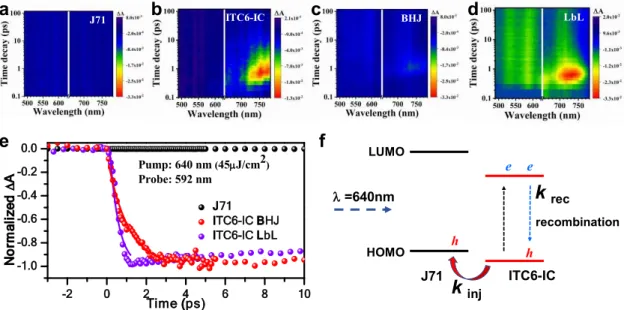
donor-acceptor interface plays a major role in efficient charge generation. Thus, we further investigated the exciton relaxation dynamics of the BHJ and LbL blends using femtosecond transient absorption spectroscopy (TAS). Fig. 5a-5d show the spectro-temporal TA maps of pristine J71 film, ITC6-IC film, BHJ, and LbL blends, respectively. In order to observe the hole injection dynamics from ITC6-IC to J71 in the blends, TA spectra were measured under low excitation fluences (45 U J 2). While all samples are pumped by 640 nm (1.95 eV) laser pulses.
Note that the photoinduced transmission changes / 0 of all samples are positive, representing
the bleach of the lowest exciton state. As shown in Fig. 5a, no decay of the TA signal intensities for J71 film can be observed in the timescale up to 100 ps. In contrast, a significant decay of the TA single intensities can be found in the pristine ITC6-IC film (Fig. 5b). In the same intensity scale, we further found that the TA signal intensities decay of LbL bend (Fig. 5d) faster than that of the BHJ blend (Fig. 5c) under the same excitation fluence. This result indicates that a more efficient hole transfer channel appears in the LbL blend as compared to its BHJ counterpart. Furthermore, we monitored the charge separated polaron dynamics (592 nm) of both blended films (Fig. 5e), indicating the more effective move of hole in LbL blend. We also calculated the hole injection rate constant (kinj), i.e., hole injection time by fitting the
TA decay curves with a single exponential function. Of note is that the fitting results reproduce the experimental results well (Fig. 5e).
The hoe injection efficiencies in both BHJ and LbL morphologies can be calculated according to the equation of = /( + ),[55, 56] where is the hole injection efficiency in
blend film and is the charge recombination rate. In the BHJ blend, the is estimated to be as high as 89.7%. The higher phase separation is probably a reason for the efficient “hole injection efficiency” in the BHJ blend. Interestingly, the of LbL blend is 95.3%, which is higher than that of BHJ blend. It indicates the more efficient exciton diffusion and charge generation in the LbL morphology with a p-i-n like structure depicted in Fig. 3g.
Both BHJ and LbL blends are also pumped by 470 nm (2.64 eV) laser pulses for investigating the photoinduced electron transfer from donor to acceptor (Fig. S9). As shown in Fig. S9d, no bleach can be found in the region of 500-600 nm in the LbL blend, indicating that the photoexcited electrons in J71 have injected into ITC6-IC very fast less than one ps. In contrast, as provided in Fig. S9c, there is a little bleach signal which suggests the injection of photoexcited electrons from J71 to ITC6-IC in the case of BHJ is a little slower compared to that of LbL blend. In addition, as shown in Fig. S9f and S9g, it was also found the bleach signals of LbL blend at 730 nm is stronger than that of BHJ blend, indicating that more photoexcited electrons from J71 to ITC6-IC were injected in the LbL blend. These results are in agreement with the PL quenching efficiencies of both blends, which also indicate reasonably efficient exciton dissociation in the LbL blend.
We also studied the charge photo-generation of relevant devices by examining the photocurrent at the saturation point where the internal field is large enough to sweep out all carriers to the electrodes prior to recombination. Fig. S10 shows the photocurrent density (Jph) versus the
internal voltage (Vin) of the devices for the BHJ and LbL systems, under illumination at 100
mW cm-2. Here we expect that almost all of the photo-generated free charges within both
systems are collected at higher Vin (> 3V). Moreover, we find the Jph at Vin = 4 V is about 18.49
mA cm-2 for the LbL device. The J
ph at the same Vin, however, is only 17.28 mA cm-2 for the
BHJ device. On one hand, just a small portion of the large Jsc losses of BHJ device compared
to LbL device can be explained by the poor optical properties of the optimal BHJ blend, as discussed in Fig. 4. On the other hand, the loss in Jsc in BHJ device may be partially attributed
to the unbalanced and poor charge carrier transport as well as an increased non-geminate recombination. These assumptions will be experimentally verified in the next section.
-2 0 2 4 6 8 10 -1.0 -0.8 -0.6 -0.4 -0.2 0.0 J71 ITC6-IC BHJ ITC6-IC LbL N o rm a li z e d A Time (ps) Pump: 640 nm (45 J/cm2) Probe: 592 nm HOMO LUMO J71 ITC6-IC =640nm h e e h recombination
k
reck
inj J71a
f
e
d
c
b
ITC6-IC LbL BHJFig. 5. The fs-ns transient dynamics for the pristine (a) J71 and (b) ITC6-IC films as well as
their (c) BHJ and (d) LbL blends pumped at 640 nm and monitored at the same intensity scale of time decay. (e) The fs-ns transient dynamics for the BHJ and LbL blends pumped at 640 nm and monitored at 592 nm. The solid lines represent the multiexponential fitting of these dynamics. (f) Schematic illumination of hole injection dynamics from ITC6-IC to J71 for BHJ and LbL blends.
2.5.3. Charge Transport Properties
To investigate the effects of BHJ and LbL morphologies on the charge transport properties, we firstly did space charge limited current (SCLC) measurements on representative BHJ and LbL hole-only devices, as presented in Fig. S11. The hole mobilities are 4.66×10⁻⁴ cm2V-1s-1 for
BHJ blend and 3.75×10⁻⁴ cm2V-1s-1 for LbL blend, respectively. The hole mobility values of
LbL hole-only diodes were slightly lower than that of the BHJ system, probably resulting from their different vertical phase separation. More acceptor materials were enriched on the top of LbL blend as depicted in Fig. 3g, which can inevitably suppress the delivery of holes.[36] In
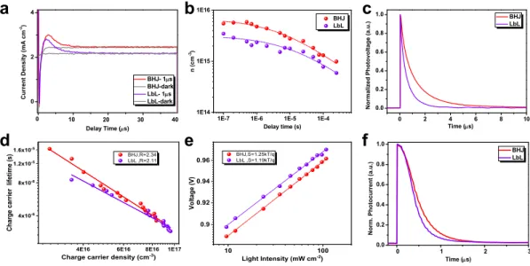
addition, we also employed photo-induced charge carrier extraction by linearly increasing the voltage (photo-CELIV) over the nanosecond-microsecond B (5U(C time regime to determine the ambipolar charge extraction from an actual photovoltaic device. Fig. 6a shows the photocurrent transients recorded by applying a 2V/40 U( linearly increasing reverse bias pulse to the BHJ and LbL solar cells after a 1 U( delay time. To determine the mobility, fourteen photo-CELIV curves have been recorded using different experimental conditions for each sample, differing in delay time, applied voltage, (Fig. S12). The average mobilities in the devices are provided
device (8.41×10⁻⁵ cm2 VW sW ). Thus, it can be concluded that charge carriers can be
transmitted more efficiently in a real LbL device.
0 2 4 40 30 20 10 BHJ- 1 s BHJ-dark LbL- 1 s LbL-dark C ur rent D ensi ty (m A cm -2) Delay Time ( s) 0 0 1 2 3 0.0 0.2 0.4 0.6 0.8 1.0 N or m . P hot ocur rent ( a. u. ) Time ( s) BHJ LbL
4E16 6E16 8E16 1E17 4x10⁻⁶ 8x10⁻⁶ 1.2x10⁻⁵ 1.6x10⁻⁵ BHJ,R=2.34 LbL ,R=2.11 C h a rg e c a rr ie r l if e ti me ( s )
Charge carrier density (cm-3)
0 2 4 6 8 10 0.0 0.2 0.4 0.6 0.8 1.0 N or m al iz ed P hot ovol tage (a. u. ) Time ( s) BHJ LbL
1E-7 1E-6 1E-5 1E-4
1E14 1E15 1E16 BHJ LbL n (cm -3) Delay time (s) 10 100 0.9 0.92 0.94 0.96 BHJ,S=1.25kT/q LbL ,S=1.19kT/q V o lt a g e ( V ) Light Intensity (mW cm-2)
a
b
c
d
e
f
Fig. 6. (a) The photo-CELIV traces for the BHJ and LbL devices after a delay time of 1 s. The
dark CELIV traces are also shown in this Figure. (b) Numbers of extracted carrier as a function of delay time and the fit. (c) Transient photo-voltage measurements of BHJ and LbL devices. Charge carrier lifetime, obtained from TPV, as a function of charge carrier density (n), calculated from CE measurements under Voc conditions. The solid lines represent linear fits of
the data. (e) Voltage against light intensity of the relevant devices. Intensities are corrected for AM1.5G spectral mismatch. (f) Normalized TPC data for the BHJ and LbL solar cells. The illumination pulse intensity was 150 mW cm-2 (a light pulse of 50 U(C"
2.5.4. Charge Carrier recombination and extraction
The time-dependence of charge carrier density was also studied in order to investigate the recombination mechanisms of charge carriers in the BHJ and LbL blends. As shown in Fig. 6b, the number of extracted carriers reduces with increasing delay time between photogeneration and extraction due to various recombination processes in the devices. Furthermore, using the following equation ( ( ) = (0)/(1 +
( )
), where (0) is the initial density of photogenerated carriers at t = 0 and is the time-independent parameter), the effective 2nd orderrecombination coefficient BXB, or known as bimolecular recombination coefficient) were
calculated.[49] Relevant parameters fitted and calculated by the above-mentioned equation are
summarized in Table S5. It is strange that the initial density of photogenerated carriers of BHJ blend is higher than that of LbL blend, probably resulting from the different vertical phase separation. Because the laser shines directly into the anode electrode (ITO (indium tin oxide)/ PEDOT: PSS (poly(3,4-ethylenedioxythiophene) polystyrene sulfonate)) and passes through the active layer. As a result, more photogenerated carriers occurred in the BHJ blend, which
also explains the shorter bimolecular recombination coefficient (5.59×10⁻⁵ s for BHJ blend and
1.31×10⁻⁴ s for LbL blend, respectively). We further calculated the transient time ( = 2
, where d is the film thickness).[36] The values are 2.38×10⁻⁷ s for BHJ device and
1.23×10⁻⁷ s for LbL device. This result is also identical to the transient photovoltage (TPV)
measurements, as presented in Fig. 6c. The BHJ device showed a carrier lifetime of 3.4 U( when the light intensity is around 2.5 suns, whereas the lifetime of J71/ITC6-IC system using a LbL structure decreased to 2.8 U( at the same intensity. It may be ascribed to less charge recombination and fewer traps within the LbL blend supported by the above-discussed morphology characterizations and the light intensity dependence of the open-circuit voltage (Voc) and Jsc data discussed in the following. Additionally, as shown in Table S5, the longer
drift length of the charge carriers ( = 466 nm, is that the mean distance over which the charges can move before significant recombination occurs) indicates that carriers are able to travel significantly longer distances in the LbL blend without considerable recombination as compared to the BHJ blend ( = 379 nm).
In order to directly figure out the situations of carrier recombination in these two blends, we combined the TPV and CE techniques to yield the charge carrier lifetime X as a function of charge carrier density under open circuit conditions, 1(n) (Fig. 6d).[36] Note that the 1 and n
values in BHJ or LbL treated devices are comparable. Here, a non-geminate recombination order R (R = Z[ C can be calculated via the equation = 0( 0 , where X0 and n0 are
constants and Z is the so-called recombination exponent.[5, 57] Generally, a recombination order
higher than two is attributed to the effect of trapping and release in energetic traps, as well as morphological traps.[10, 44, 46] As shown in Fig. 6d, a slightly higher recombination order value
(R = 2.34) for the BHJ device as compared to the LbL device (R = 2.11) can be found. In addition, multiple studies have demonstrated that the light intensity dependence of the Voc can
directly provide insight into the role of trap-assisted recombination versus 2nd order
recombination at the open circuit condition. The Voc and light intensity (I) can be correlated by
the expression[46] of , where E
gap is the energy difference between
= $gap% $&ln[(1% ') (
2
') ]
the highest occupied molecular orbital (HOMO) of the electron donor and the lowest unoccupied molecular orbital (LUMO) of the electron acceptor, q is the elementary charge, k is the Boltzman constant, T is temperature in Kelvin, P is the dissociation probability of the electron-hole pairs into free carriers, the recombination constant, Nc the density of states in
the conduction band, and G the generation rate of electron-hole pairs. Following the rules, the formula predicts a slope S = (kT/q) of the Voc versus the natural logarithm of the incident light
intensity. This implies that the slope of Voc versus ln(I) is equal to kT/q for 2nd order
recombination. When trap-assisted recombination is involved, a stronger dependency of Voc on
the light intensity is observed.As shown in Fig. 6e, the LbL device exhibits a logarithmic dependence on light intensity with a slope of 1.19 kT/q, which is close to kT/q for a 2nd order
recombination process. Moreover, the slope yields 1.25 kT/q for the BHJ device, implying that the poor BHJ blend may cause the number of trapping defects, which likely contribute to trap-assisted recombination in this blend.
Now, the remaining question is to evaluate the influence of two different morphologies on the charge collection efficiency and the dwell time of charges in the active layer prior to charge extraction at the electrodes. Here we conducted the transient photocurrent (TPC) technique carried on the devices under the short circuit condition. Fig. 6f exhibits the charge extraction of the BHJ and LbL devices at Jsc condition where the internal field equals the Vbi. The
extraction time of the BHJ device was extracted to be = 0.41 + U(. In the case of LbL device, it showed a very short lifetime of around 0.30 U(" The shorter extraction lifetime suggested that photo-generated carriers are extracted more efficiently in the LbL devices than the BHJ devices. These results also implied that the difference in FF observed in BHJ and LbL blends (Fig. S15) is not only a consequence of different non-geminate recombination rates but also the rate of charge extraction. In short, the results of the carrier recombination dynamic analysis coupled with the voltage dependence of non-geminate recombination and charge carrier mobilities finally underpin the complex morphology outline above and give detailed insight into subtle mechanisms being responsible for device parameters.
3. Discussion
The choice of processing conditions based on BHJ and LbL approaches enables changing the D/A interfacial area, fine-tuning the molecular ordering and vertical phase separation. This, in turn, is likely to cause changes in the fundamental photo-physical processes as depicted in Fig. 4-6. We suggest that the LbL approach could effectively suppress the bulk recombination and reduced the traps or defects. In this section, we will further evaluate the BHJ and LbL technologies, discuss the relationships between blend morphology, physical dynamics, photovoltaic parameters, and device stability, and probably give a real inspiration of which approach is more suitable for the large-area fabrication of OSCs in the commercial applications.
We schematically picture the nanoscale morphology of the two blends in Fig. 3g with the main difference being the composition of the vertical phase. In general, vertical stratification of electron donors and acceptors during their thin-formation process is a complex process resulting from the synergistic effects of thermodynamics, kinetics, free-surface or interfacial surface energy, interface effects, centripetal forces, chemical reaction between the active layer and substrate, etc. The processing conditions,[58-63] such as the solubility of D and A materials,
solvent evaporation rate, interaction between components, liquid and solid additives, post-treatments, free energies of the components, surface of substrates and device architecture, can all be effective in turning the final film morphology. In the film formation of BHJ blend, phase separation will occur due to the reduced solubility of D and A, and the interactions between the D materials, the A materials, and the solvent. The changes of film drying time (or rate of solvent evaporation) should have an impact on the vertical stratification in photovoltaic blends.[64] The
failure of a quick diffusion of solvent molecules from the bottom to the top to supplement the concentration will lead to a “skin” formation in the partly wet film, and substantially postpone the rest of the drying process.This indicates that any lateral or vertical morphology that is formed during the film-formation process of BHJ blend might be a kinetics-limited state, and could be controlled by selective dissolubility and free energies of donors, acceptors, and the substrate surface. Thus, it is hugely difficult to obtain ideal vertical profile by using BHJ method. Unlike the BHJ blend (Fig. 3g), the donor material is enriched in the bottom of LbL blend, and the acceptor material is enriched in the upper layer. From this analysis, we further conclude that the LbL processing approach primarily acts as a plasticizer to enable ripening of the domains, aggregation of the molecules, and eventually vertical phase separation. Because the LbL layer was formed by doctor-blading solution of acceptor materials on the corresponding fry film only containing the donor materials. Deposition onto the pristine donor films held at different temperatures enables different film drying times, and therefore kinetically allows different times for component diffusion and stratification. While high-quality LbL morphology with a p-i-n like vertical structure can be accomplished by adjusting blade speed and substrate temperature and shows the superior PCEs of LbL devices as compared to that of BHJ devices. Although the above-mentioned factors, including thermodynamics, kinetics, surface free energy or selective dissolubility, etc., still possibly influence the vertical phase components, the LbL approach itself shall be the main origin of the vertical stratification. Thus, unlike the BHJ method for applying into the optimization of active layer, which is mainly implemented through the trial-and-error experimental routines, LbL technology is a more rational control approach of vertical stratification for high-performance OSCs.
3.2. Structure governing device dynamics and efficiencies
It is well accepted in the OSC community that film microstructures and aggregation at molecular length-scales as well as vertical phase separation play critical roles in controlling the optoelectronic properties, via its effects on light absorption, exciton dissociation, charge generation, carrier transport, and recombination. For this reason, a growing understanding of the use of processes to control morphology and tune physical dynamics through BHJ and LbL processing methods should be highlighted. It will be allowing rapid progress to be made in the development of highly efficient OSCs.
Based on the above morphology analysis from GIWAXS and TOF-SIMS measurements, it is convincing that the increase in D/A aggregations in the LbL blend is directly reflected in the diffraction data. The impact of their morphologies on device performance, especially on Jsc, can
partially depend on the absorption coefficient of active layers and the photoabsorption rate of their devices. Importantly, both BHJ and LbL blends can show the suitable miscibility of donor and acceptor materials, demonstrated by the above-mentioned PL and TRPL as well as the saturated photocurrent density measurements. That means there is not a common morphological limitation that impacts exciton dissociation and charge generation, which have been demonstrated by their similar saturated photocurrent densities in BHJ and LbL devices (Fig. S10). In BHJ devices, charge trapping in pure domains is not an issue. Because J71 polymer entanglements enable connectivity for charges throughout the BHJ blend even down to J71 compositions of a few volume percents. However, the BHJ blend with the small, mixed domains shows a higher D:A miscibility as compared to the LbL blend, which increases the probability of charge trapping and carrier recombination.
Interestingly, the LbL active layer with suitable vertical phase separation and high crystalline domains preserved the interfacial exciton harvesting and even showed the higher hole injection efficiency and ultrafast charge generation supported by the TA measurements. On one hand, we thus propose that in the LbL blends, a possible target goal would be high miscibility to ensure mixed phases that promote charge percolation through the minority component, but maintain the ability of the majority component to aggregate (Fig. 3g). On the other hand, due to the uniqueness of the non-fullerene materials,[65] the further enhancements to diffusion
lengths may even obviate the need for the bulk heterojunction morphology. Our result provides impetus for further measurements on other BHJ, and LbL blends to probe the generality of these morphology guidelines to maximize performance.
Apart from the requirements of small, highly ordered crystallizes or aggregated domains in an ideal active layer, a suitable vertical phase separation is also essential, which significantly affects all stages of charge generation-but particularly charge transport and extraction. The unsuitable vertical phase with small scale of BHJ blend limit p-type and n-type domain connectivity for charge transport in devices, even though it shows a slightly high hole-only mobility. Indeed, space-charge build-up measured via TPC for the BHJ devices goes hand-in-hand with the pure disconnected BHJ domain resulting in large populations of bound geminate pairs and charges trapped in domain islands. Moreover, even when optimized the BHJ blend, non-geminate recombination losses from trapping continue to play a significant role in the BHJ systems as discussed above. Consequently, TPC charge extraction remains low in the optimized BHJ device, consistent with charges being spatially trapped in unsuitable vertical phase separation. In contrast, with the improvement of vertical phase separation by the introduction of LbL approach in the film formation, improved charge transport and extraction prevails over the extra carrier losses in devices. This explains the concurrent rise in Jsc and FF values
compared with the BHJ system, in spite of LbL blend still having good mixing propensity and high PL quenching efficiency. As depicted in Fig. 3g, D/A mixing in the intermediate domain while retaining slightly larger pure domains at the top and bottom sides is not only beneficial for exciton diffusion and dissociation but also can be linked to reduced charge recombination. Total carrier recombination losses in OSCs determined by a competition between recombination and extraction. Several studies demonstrate that identifying high domain purity as important to maintain low recombination rates by separating charges into spatially segregated domains.[4, 49, 66] Thus, direct, trap-free charge percolation routes through mixed phases and
efficient Q5Q stacking close to opposite ends are the likely reasons for the low non-geminate recombination losses observed in the LbL blends.
Overall, we have shown that the BHJ devices endure slower charge generation, more carrier trapping, and poorer extraction compared to the LbL solar cells. A suitable vertical phase separation would likely translate into a decrease in recombination losses and an increase in charge mobility across the active layer, leading to slightly higher Jsc and FF values in LbL
devices. As a result, the PCEs of J71: ITC6-IC system can increase from 10.41% for the BHJ bladed blend to 11.47% for the LbL bladed blend, which is also similar with the reported PCE of spin-coated BHJ blend.[47] Two points should be highlighted here for the comparison of
coating approaches. On one hand, engineering the local molecular orientation and crystallinity at interfaces between active layer and electrodes are likely pathways to such an efficiency improvement of BHJ devices.[67] On the other hand, although suitable vertical phase separation
can be easily achieved by LbL approach, the lack of control over crystal size at the time of solution processing probably remains a key limitation.
3.3. Structure deciding energy loss of blend
Apart from the Jsc and FF values, we also found that the LbL approach could efficiently reduce
the energy loss of J71: ITC6-IC system. As shown in Table S1, the BHJ device with a Voc of
950 mV shows an energy loss of 0.72 eV, while the LbL blend with a Voc of 968 mV provides
a smaller energy loss of 0.702 eV. Better vertical phase-separated morphology of the LbL blend can effectively narrow the shape of the density of state (DOS).[68] Thus, the corresponding
electron quasi-Fermi level ( , ) of acceptor can be up-shifted meanwhile the hole quasi-Fermi level ( ) will be down-shifted,[69] as depicted in Fig. S16. In addition, a preferable way of
,-quantifying energy and voltage losses in OSCs is to use the detailed balance theory as described in the references.[70, 71] Following the Shockley-Queisser (SQ) limit, the voltage losses (q V
oc)
can be categorized into three different terms (q Voc = (Egap-qVSQ oc)+(q Vrad oc)+(q V
non-rad oc)).[71] We quantified the energy and voltage losses by characterizing Fourier-transform
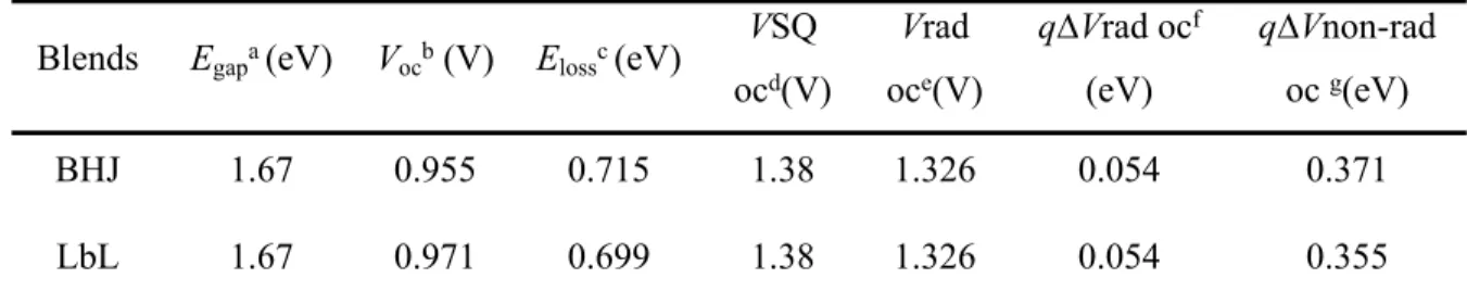
photocurrent spectroscopy external quantum efficiency (FTPS-EQE) and electroluminescence (EL) spectra in these investigated solar cells, as presented in Fig. 7.The calculation results are summarized in Table 1. Both of BHJ and LbL devices show the same E1=Egap-qVSQ oc with
a value of 0.29 eV and E2 =q\Vrad oc with a value of 0.054 eV, respectively. The third loss
\E3 = q\Vnon-rad oc is the difference between the qVrad oc and the measured qVoc under
AM1.5G simulated solar spectrum. The LbL solar cells gave an extremely smaller q\Vnon-rad oc of 0.355 V as compared to that of BHJ devices (0.371 V) . The smaller q\Vnon-rad oc value in LbL solar cell indicates that the LbL approach has great contribution to reducing non-radiative recombination, which have been demonstrated by the above-mentioned physical measurements. Overall, replacing BHJ with LbL process for the film formation of active layer could further modify the DOS, while indcuing a better Fermi level alignment with electrodes, reducing non-radiative recombination, and thus increasing the Voc of the relevant devcies to a
1.0 1.2 1.4 1.6 1.8 2.0 2.2 10-7 10-6 10-5 10-4 10-3 10-2 10-1 100 101 EQEFTPS EQE EL/ bb F T P S _ E Q E EL LbL 10-7 10-6 10-5 10-4 10-3 10-2 10-1 100 101 Energy (eV) N o rm a li z e d E L 1.0 1.2 1.4 1.6 1.8 2.0 2.2 10-7 10-6 10-5 10-4 10-3 10-2 10-1 100 101 EQEFTPS EQE EL/ bb F T P S _ E Q E EL BHJ 10-7 10-6 10-5 10-4 10-3 10-2 10-1 100 101 Energy (eV) N o rm a li z e d E L
a
b
Fig. 7 FTPS-EQE (red lines) and EL (green lines) spectra of the (a) BHJ and (b) LbL
blade-coated OSCs.
Table 1. Summary of parameters measured and calculated from FTPS-EQE and EL.
Blends Egapa (eV) Vocb (V) Elossc(eV)
VSQ ocd(V) Vrad oce(V) q\Vrad ocf (eV) q\Vnon-rad oc g(eV) BHJ 1.67 0.955 0.715 1.38 1.326 0.054 0.371 LbL 1.67 0.971 0.699 1.38 1.326 0.054 0.355 aE
gap: The band gap (1.67) of ITC6-IC was determined from the crossing point between the
emission and absorption spectra, as presented in Fig. S17; bVoltage values calculated for
J71:ITC6-IC devices based on the BHJ and LbL blends; cV
oc loss is equal to the difference of
Egap and Voc; dVocSQ: Schokley-Queisser limit to Voc; eVocrad: radiative limit to Voc, measured
using EQE-EL; f6$
ocrad: voltage losses due to non-ideal absorption (it was calculated from EL
and FTPS measurements); g6$
ocnon-rad: voltage losses due to non-radiative recombination only.
3.4. Structure Influencing Stability Issues
Our results are very interesting since device performance only improves slightly for the LbL blend when the LbL blend shows the dramatically different vertical phase separation with the BHJ blend. This drives us to explore further the stability issues of OSCs, which generally are controlled by the blend microstructure.[4] In the following section, we systematically
investigated the stability issues of BHJ and LbL blends, including photo-stability, thermal stability, and mechanical stability.
3.4.1. photo-stability of BHJ and LbL blends
Many studies have been shown that enhanced donor crystallinity and suitable phase separation could improve the device photo-stability. However, less reports have been to depict the correlation between the vertical phase separation and device stability. Based on this point, we explored the long-time light-induced stability of the BHJ and LbL devices tested in nitrogen
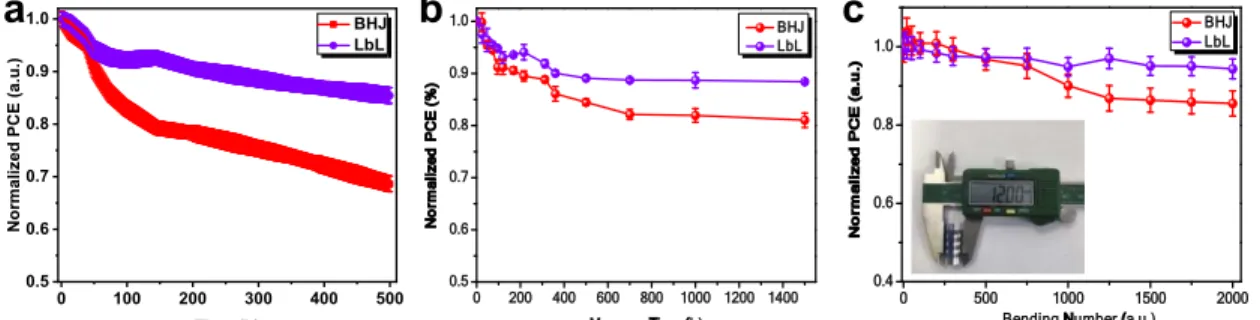
glovebox at room temperature. Fig. 8a shows the relative change of the recorded PCEs of these two BHJ and LbL devices. BHJ devices show a PCE degradation down to 68% within 500 h, respectively, while LbL device showed the lowest PCE loss down to ca. 85% during the same period. BHJ blend shows the poorer stability with a light-induced PCE degradation of around 32% after 500 h, mainly resulting from Jsc, and FF losses (Fig. S18). The LbL system is more
stable under illumination within 500 h as compared to the BHJ system. At this point, we suggest to correlate the higher light stability to the suitable vertical phase separation with enhanced donor and acceptor aggregations.[72] Notably, the degradation behavior depends strongly on the
approach of film formation while all other factors are the same. Further GIWAXS measurements (Fig. S19 and S20) demonstrated that the D and A materials were separated in the BHJ blend and thus formed large domains, which resulted in the obvious burn-in loss.
0 500 1000 1500 2000 0.4 0.6 0.8 1.0 N o r m a li z e d P C E ( a .u .)
Bending Number (a.u.) BHJ LbL 0 100 200 300 400 500 0.5 0.6 0.7 0.8 0.9 1.0 N o rma li z e d P C E ( a .u .) Time (h) BHJ LbL 0 200 400 600 800 1000 1200 1400 0.5 0.6 0.7 0.8 0.9 1.0 N o rm a li z e d P C E ( % ) Measure Time (h) BHJ LbL
a
b
c
Fig. 8 (a) Variation of normalized average PCE losses over illumination time over 500 hours
for the BHJ and LbL devices based on ITO/PEDOT:PSS/BHJ or LbL/PDINO/Ag, measured in a dry nitrogen atmosphere; (b) Variation of normalized PCE of the BHJ and LbL devices annealed at 120 °C over 1500 h; (c) The blending test of flexible BHJ and LbL based OSCs. The inset shows the photo of blending cycles with radius of 6 mm.
3.4.2. Thermal stability of BHJ and LbL blends
Apart from light, accumulated heat from illumination are unavoidable, which can severely change the optimized blend morphology in a short time and further significantly lead to PCE losses.[72, 73] This reason is that an optimal morphology generally is a metastable state, and
further move toward to a thermodynamic equilibrium state to form large phase separations, mainly accelerated by the accumulated heat. Thus, this drives us to investigate the thermal stability of BHJ and LbL blends for checking which processing method is more suitable to meet the requirements of thermal stability in OSCs. Here, better thermal stability was also found for the LbL blend as compared to the BHJ blend. As shown in Fig. 8b, BHJ devices exhibited rapidly decreased device performance upon continuous annealing and maintained 81% of initial PCEs after baking at 120 °C under inert atmosphere for 1500 h. It should be noted that thermally induced degradation of BHJ blend was mainly due to the degradation of Jsc, probably resulting
from the huge changes in blend morphology demonstrated by the GIWAXS measurements (Fig. S19). In contrast, the device performance of LbL devices maintained 88% of initial performance, probably due to the much stable blend morphology (Fig. S20). As compared to the BHJ blend, the LbL morphology changed little before and after baking at 120 °C for 1500 h.
3.4.3. Bending stability of BHJ and LbL blends
As expected, this LbL processing technology also affords a new opportunity in flexible OSCs. Since the BHJ and LbL blends show the different vertical phase separation, which probably also influence the mechanical stability of relevant active layers. Thus, we also measured the blending stability of BHJ and LbL blends, as shown in Fig. 8c. It exhibits the normalized PCEs of the BHJ and LbL devices as a function of blending cycles with radium of 6 mm. The BHJ coated flexible device based on the configuration of polyethylene terephthalate (PET)/ITO-metal-ITO (IMI)/PEDOT: PSS/active layer/PDINO/Al remains approximately 85% of its initial PCE after 2000 blending cycles. While the LbL bladed, one shows the 92% of its inial PCE at the same condition. Based on this point, the more stable blend morphology for the application of rigid and flexible OSCs and solar modules is achieved by the LbL processing approach, which can effectively reduce the efficiency-stability gap.
4. Conclusion
In summary, we first conducted an in-depth study on the film formation, optimization, and degradation processes of J71: ITC6-IC doctor-bladed blends fabricated by two different processing technologies, BHJ and LbL. Furthermore, we correlated different 3D morphological characteristics to the photocurrent generation and extraction processes of BHJ and LbL blends as well as their stability issues in devices. After such a comprehensive study, it can be found that the LbL blade-coating process exhibits many advantages over the widely used BHJ method. The details are shown in the following: Firstly, as compared to the BHJ blade-coating technology, the LbL blading approach not only facilitates ITC6-IC acceptor molecules to mix with the J71 donor for achieving a thermodynamically more favorable nanomorphology with suitable D/A interface area, but also to improve the formation of larger, separated D/A domains, and the segregation of acceptors towards the top of the active layer. This desired hierarchical morphology can be easily obtained through independently controlling and optimizing the D and A deposition, indicating that the LbL solution processing technique is a promising and cost-effective strategy. Secondly, the 3D geometry of the LbL blend as compared to the BHJ blend
allows for achieving higher light absorption coefficient and thus for improved charge generation in the active layer. Thirdly, the suitable morphologies and interfaces between donors and acceptors can effectively provide a strong charge transfer driving force and small energy loss of charge transfer simultaneously. Meanwhile, this p-i-n like structure is also beneficial for charge transport and collection at the appropriate electrodes, so that non-geminate recombination can be further reduced. Thus, films fabricated with the J71: ITC6-IC system yield a 10% increasement in PCE up to 10% with the LbL doctor-bladed approach. Finally, the LbL blend with a suitable vertical phase separation exhibits a more stable morphology than that of BHJ blend. As expected, relevant LbL bladed systems can meet the requirements of long-term irradiation and thermal stability as well as compatible mechanical stability in flexible devices.
Overall, our work demonstrates that the LbL blade-coating approach is a promising strategy and even a superior alternative to the BHJ method for controlling the blend morphology, and presents good generality, high efficiency, and good stability. We also call on researchers to provide more efforts in this coating technology.
Supporting Information
Supporting Information is available from …
Acknowledgments
This work was financially supported by the National Natural Science Foundation of China (Grant No. 21702154 and 51773157). We also thank the support of the opening project of Key Laboratory of Materials Processing and Mold. L.Y. and H. A. were support by the U.S. Office of Naval Research (ONR, Grant No. N000141712204). TOF.SIMS was performed at the Analytical Instrumentation Facility (AIF) at NCSU, which was supported in part by the State of North Carolina and the National Science Foundation (Award No. ECCS.1542015). S.K. acknowledges the Deutsche Forschungsgemeinschaft for the award of a personal fellowship (408012143).