Preliminary Design Report
! " # $ %%&%&%%' ( ) $ *+ %% Chapter 1 - Background ... 1 Introduction ... 1 Condition Assessment ... 1 Reliable Capacity... 2Forcemain Header Structural Integrity ... 2
Wetwell Corrosion ... 2
Manhole Corrosion ... 2
O&M and Safety Concerns ... 2
Chapter 2 - Design Criteria ... 3
Flow ... 3
Additional Pumping to Handle Emerald Relief Trunk Flows ... 3
Reliability and Redundancy ... 3
Pumping Systems ... 4
Piping ... 5
Flow Monitoring ... 5
Valves, Gates, and Actuators ... 6
Pump Backflow Protection Valve ... 6
Pump Discharge Isolation Valves ... 6
Forcemain Isolation Valve ... 6
Wetwell Isolation Gate ... 6
Wetwell ... 6
Emergency Bypass Pumping ... 7
Odor Control ... 7
Standby Power ... 7
Sound Attenuation ... 7
Auxiliary Systems ... 7
Ventilation ... 7
Compressed Air System ... 8
Water System ... 8
Hoist and Monorail Systems ... 8
Operations and Maintenance ... 8
Architectural/Landscape Requirements ... 8
Electrical Power/Lighting ... 8
Instrumentation and Control ... 9
Chapter 3 - Alternatives Analysis ...10
Alternative 1 – Drywell/Wetwell Expansion ... 10
Alternative 1 Construction Sequencing ... 13
Alternative 1 Advantages and Disadvantages ... 13
Cost Estimate ... 13
Alternative 2 – Trench Style Lift Station in Existing Facility ... 15
Alternative 2 Construction Sequencing ... 16
Alternative 2 Advantages and Disadvantages ... 16
Cost Estimate ... 18
Alternative 3 – New Trench Style Lift Station ... 19
Alternative 3 Construction Sequencing ... 20
Alternative 3 Advantages and Disadvantages ... 20
Cost Estimate ... 23
Alternatives Analysis Summary and Recommendations ... 24
Preliminary Design Report
! " # $ %%&%&%%' ( ) $ *+ %%
Project Description ... 25
Reliability and Redundancy ... 26
Hydraulic Analysis ... 26
Inlet Gravity Sewer Sizing ... 26
Effluent Force Main Sizing ... 27
Lift Station Pump and System Curves... 28
Demolition ... 28
Site Improvements ... 34
Trench Style Lift Station... 34
Lift Station Odor Control ... 36
Emergency Bypass Pumping ... 37
Access Provisions ... 37
Piping, Valves, and Flow Monitoring ... 38
Electrical Power/Lighting ... 43
Standby Power ... 43
Instrumentation and Control ... 44
Pump Operation ... 44
Operations Building ... 52
Chapter 5 - Project Implementation ...53
Construction Sequencing... 53
Project Schedule ... 54
Drawings and Specifications ... 54
Construction Cost Estimate ... 57
,
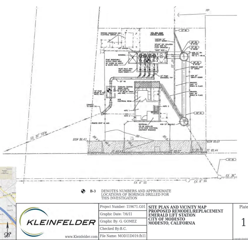
-Figure 1. Existing Emerald Lift Station Site Plan ... 1Figure 2. Site Plan – Alternative 1 ... 12
Figure 3. Site Plan – Alternative 2 ... 17
Figure 4. Site Plan - Alternative 3 ... 21
Figure 5. Alternative 3 Section ... 22
Figure 6. System Curve ... 30
Figure 7. Emerald Site Demolition Plan ... 31
Figure 8. Emerald Lift Station Demolition Plans ... 32
Figure 9. Emerald Lift Station Demolition Sections ... 33
Figure 10. Emerald Site Plan ... 35
Figure 11. Emerald Site Piping Plan ... 39
Figure 12. Emerald Enlarged Lift Station Plan ... 40
Figure 13. Emerald Lift Station Section A ... 41
Figure 14. Emerald Lift Station Electrical Site Plan ... 46
Figure 15. Emerald Lift Station MCC Elevation ... 47
Figure 16. Emerald Lift Station Single Line Diagram ... 48
Figure 17. Emerald Lift Station Process and Instrumentation Diagram ... 49
Preliminary Design Report
! " # $ %%&%&%%' ( ) $ *+ %%
.
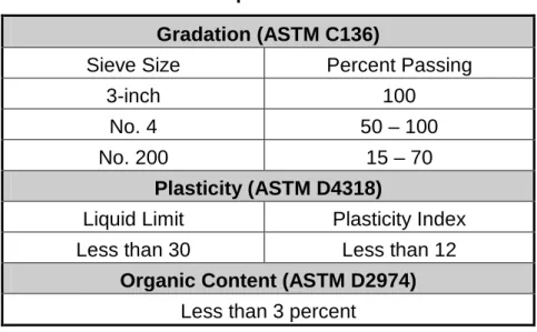
Table 1. Flow Velocity Design Criteria ... 5
Table 2. Flow Meter Design Criteria ... 5
Table 3. Preliminary Pump Selection ... 10
Table 4. Alternative 1 Advantages and Disadvantages ... 13
Table 5. Alternative 1 Cost Estimate ... 14
Table 6. Alternative 2 Advantages and Disadvantages ... 16
Table 7. Alternative 2 Cost Estimate ... 18
Table 8. Alternative 3 Advantages and Disadvantages ... 20
Table 9. Alternative 3 Cost Estimate ... 23
Table 10. Matrix Analysis ... 24
Table 11. Preliminary Pump Selection ... 25
Table 12. Inlet Sewer Sizing Calculation Summary ... 27
Table 13. Project Schedule ... 54
Table 14. Proposed List of Drawings ... 54
Table 15. Proposed List of Specifications ... 56
Table 16. Preliminary Design Cost Estimate ... 57
/
Appendix A – Hydraulics
Appendix B – Manufacturer Information Appendix C – Meeting Agendas and Minutes Appendix D – Survey Report
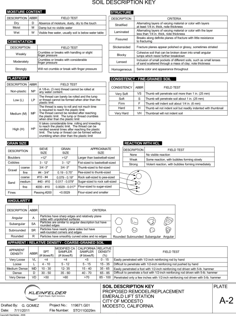
Appendix E – Geotechnical Report
Preliminary Design Report
! " # $ %%&%&%%' ( ) $ *+ %%
The Emerald Lift Station is located between 307 North Emerald Avenue and the Modesto Irrigation District Lateral No. 4, near the intersection of Emerald and Laurel Avenues. The station was constructed in 1953, underwent a ventilation project in 1988, and was significantly rehabilitated in 1994. The lift station receives flow from the east through a 36-inch gravity sewer from a manhole within Emerald Avenue and from the west through a 10-inch gravity sewer from a manhole in the alley behind the station. The two gravity sewers combine at a manhole on site prior to entering the wetwell through a 36-inch gravity sewer. The drywell
contains two Fairbanks Morse 20 hp pumps with shafted motors and one 30 hp Wemco Hidrostal dry pit submersible pump. Each pump’s suction piping contains an isolation valve and their discharge piping contains an isolation and check valve. The pumps’ discharge piping combines into a single 24-inch header located in the drywell on the intermediate level on the south side of the building before reducing to a 20-inch cast iron forcemain. The 20-inch forcemain crosses beneath the Modesto Irrigation District Lateral No. 4 and discharges to gravity at a manhole within Emerald Avenue. The station contains a permanent 100 kW standby generator for backup power. The Emerald Lift Station site plan is shown in Figure 1.
The Emerald Lift Station cannot currently pump incoming PWWF reliably with one of the three pumps out of service. The required firm capacity of the station should be 3,100 gpm with the largest pump out of service. In addition, the City indicated that in the future, flow will be diverted from the Emerald Trunk to the West Trunk through the new Emerald Relief Trunk. If the Emerald Relief Trunk is taken out of service in the future for inspection or repair work, the Emerald Lift Station’s anticipated incoming PWWF will be 6,800 gpm.
A condition assessment of the Emerald Lift Station was conducted under the City of Modesto’s 2007 Wastewater Collection System Master Plan. Based on the findings of the condition assessment, the Master Plan concluded that the Emerald Lift Station should be remodeled or replaced.
Preliminary Design Report
! " # $ %%&%&%%' ( ) $ *+ %%
Pumps at Emerald Lift Station
Manhole Corrosion
The pump station currently has the following notable deficiencies:
Reliable Capacity
All three existing pumps at the Emerald Lift Station operate during peak wet weather flow events. In addition, two of the three pumps have shafts with motors installed on the intermediate floor. These motors are still located below grade and are susceptible to flooding. The third pump was replaced with a dry pit submersible unit.
Forcemain Header Structural Integrity
The 24-inch forcemain header piping currently leaks within the pump station. The structural integrity of the pipeline is compromised as indicated by the City’s lift station O&M staff during the site visit.
Wetwell Corrosion
The wetwell surfaces are severely corroded and the structural integrity of the wetwell portion of the building is in question. The existing protective coating is peeling away from the concrete.
Manhole Corrosion
The gravity sewer manhole on site is corroded with exposed aggregate.
O&M and Safety Concerns
The lift station contains ship ladders to access the below grade portions of the drywell where the pumps, motors, and isolation and check valves are located. All below grade drywell equipment must be manually removed and positioned beneath the openings within the floors above for removal from the station since no cranes or monorail equipment are provided. Not only is this practice labor intensive, but dangerous, since the grating just inside the pump station door must be removed to facilitate the operation. If the grating is not present when the station is entered, a fatal fall could occur to the entering personnel. Other safety concerns also exist at the station including the odor control blower which does not meet NFPA 820 explosion proof requirements.
Forcemain Header Structural Integrity
Wetwell Corrosion
Removable Access Grating at Entrance to Drywell
Preliminary Design Report
! " # $ %%&%&%%' ( ) $ *+ %%
Design criteria for the Emerald Lift Station includes:
The Emerald Lift Station must be capable of pumping incoming flows between minimum dry weather flow (MDWF) and peak wet weather flow (PWWF). The PWWF for the Emerald Lift Station is defined as the required reliable/firm capacity (largest pump out of service) for the station as provided by the City of Modesto.
PWWF (with flow diverted to Emerald Relief Trunk) = 3,100 gpm (4.5 mgd) PWWF (without flow diverted to Emerald Relief Trunk) = 6,800 gpm (9.8 mgd)
The pump station will be designed with a firm capacity of 3,100 gpm (4.5 mgd). During times when the Emerald Relief Trunk’s flow is diverted to the Emerald Lift Station (or prior to diverting flows to the Emerald Relief Sewer), the pump station will be required to pump 6,800 gpm (9.8 mgd) with all units in operation. The flow of 6,800 gpm assumes that the upstream storm drain cross connections have been removed. When flows of 6,800 gpm are required to be pumped, a portable generator will be required to provide standby power to all four pumps.
Additional Pumping to Handle Emerald Relief Trunk Flows
The Emerald Pump Station will be designed to reliably pump PWWF without flows from the Emerald Relief Trunk. However, provisions will be included in the lift station to accommodate the increased flows. The lift station must have a firm capacity of 3,100 gpm and a total
capacity of 6,800 gpm.
Four electric-driven submersible pumps will be provided and will be capable of handling the PWWF with flow from the Emerald Relief Trunk. It should be noted that during this operation there will not be a standby pump nor will the permanent standby generator installed onsite be capable of handling the loads from all four submersible pumps. The standby generator will provide standby power for two of the four pumps required to pump the PWWF of 3,100 gpm which does not include the Emerald Relief Trunk flows. An electrical “Tap Box” will be included to facilitate the connection of a supplementary emergency generator should it be required to connect additional pumping capacity to emergency power. It should be no standby pump is provided under this situation.
Reliability and redundancy minimizes the probability of wastewater overflows at the pumping station and within its service area. Reliable pumping capacity is defined by the City as the
ability to pump the station's PWWF with the largest pump out of service and without Modesto
Irrigation District (MID) power. The station's reliability will also be improved in other areas as
Preliminary Design Report
! " # $ %%&%&%%' ( ) $ *+ %%
!
maintenance. Pumping units and all critical auxiliary equipment will meet reliability requirements. Reliability requirements include:
Permanent standby power to pump 3,100 gpm (4.5 mgd).
Ability to pump 3,100 gpm (4.5 mgd) with the largest pump, motor, and VFD out of service.
Redundant pump, motor, and VFD for each size of pump when pumping 3,100 gpm (4.5 mgd).
Fuel storage for the standby generator is 170 gallons. The existing tank is sized for 24 hours at full load.
Solids handling wastewater pumps (Wemco submersible). Redundant critical auxiliary equipment.
Proven equipment.
Structural and seismic design to meet codes. Structural elements and equipment bracing.
"
#
Pumping system design involves evaluation of forcemain hydraulics, pump characteristics, proper and efficient sizing, proper wetwell size, and operation and maintenance considerations. The pumping system will meet the following criteria:
Capable of pumping flows from minimum dry weather flow to PWWF without starting any pump more than 10 starts per hour. Initial analysis of wetwell size and with consideration of site constraints has shown that VFDs will be required to prevent pump cycling above 10 starts per hour.
Pump PWWF with the largest pump, motor, and VFD out of service when pumping 3,100 gpm (4.5 mgd).
Pumps suitable for raw wastewater.
Operate pumps with high efficiency range on pump curve and within manufacturer's
recommended operating range. Provide premium efficiency motors. Provide sufficient NPSH.
Prevent vortexing. Prevent cavitation.
Provide accessible isolation and check valves conforming to the City specifications. Implement pre-rotation basin (Wemco) to remove floatables and grease.
Preliminary Design Report
! " # $ %%&%&%%' ( ) $ *+ %%
$
"
Piping will be in accordance with the following criteria.
All wastewater piping will be ductile iron, pressure class 350, complying with
ANSI/AWWAC151. Fittings will conform to ANSI/AWWA C110. Pipe located in the wet well will be flanged.
Exposed piping will be adequately supported for dead and seismic loading. Hydraulic Institute Standard 9.6.6, “Rotodynamic Pumps for Pump Piping” shall be used.
Pipe lining and coating will be suitable to protect the pipe from its environment. Lining will be ceramic epoxy, Protecto 401, or equal. Buried piping will be protected by polyethylene encasement complying with ANSI/AWWA C105.
Sewage piping will be sized to meet the flow velocity design criteria outlined below.
Pipe Segment Discharge Pipe
Velocity 8 fps (maximum)
%
A magnetic style flow meter will be provided at Emerald Pump Station. The flow meter will be installed in a subgrade concrete vault on the common pump station discharge to monitor total flow from the pump station. The recommended velocity through the flow meter is between 2 and 20 feet per second (fps). Flow velocity outside of this range will result in reduced accuracy of flow monitoring. The PWWF (including West Trunk flows) is 6,800 gpm; under normal operation the PWWF is 3,100 gpm. Both flows are considered in the sizing of the flow meter. The pumps will be installed on variable frequency drives where the resulting minimum flow from the pump station will be 850 gpm, half the capacity of a single pump. This flow is also considered in the recommended flow meter size. However, based on the hydraulic analysis performed at Emerald Pump Station, the headlosses are too significant through a 12-inch or 14-inch flow meter thus drastically increasing the motor size of the pumps. Therefore, it has been determined that the optimum size flow meter is 16-inches.
!
Flow Meter Size (in)
Flow and Velocity (fps)
775 gpm 3,100 gpm 6,800 gpm
12 2.2 8.8 19.3
14 1.6 6.5 14.2
Preliminary Design Report
! " # $ %%&%&%%' ( ) $ *+ %%
&
' (
) *
)
Proper valve selection and placement is critical to the station's ease of maintenance and
operation, overall station flexibility, and reliability. The following criteria have been developed for valves at the lift station. Valve location will be selected for accessibility. Submersible pumps will have discharge valves located in a valve vault. All installed valves will be constructed of material resistant to corrosion and suitable for wastewater service.
Pump Backflow Protection Valve
Each pump discharge will include a swing check valve to prevent backflow in the system from damaging the pump. Check valves will comply with AWWA C508. Bronze materials
containing more than 16 percent zinc will be prohibited per AWWA C508.
Pump Discharge Isolation Valves
Each pump will be provided with its own discharge valve to isolate the pump from the system. Isolation valves will be non-lubricated eccentric plug type valves and be manually operated. Valve will be lined with fusion bonded epoxy. Valves will be DeZurik Model No. PEC, diameter as shown, F1, CI, T, CR*GS-6-HP8, SB, or equal.
Forcemain Isolation Valve
There is currently no isolation valve on the system between the pump station and the discharge manhole in Emerald Avenue. A manually operated plug valve is recommended downstream of the flow meter in order to isolate the flow meter and accommodate maintenance.
Wetwell Isolation Gate
A type 316 stainless steel slide gate will be provided on the wetwell influent to isolate the pump station from the gravity system. The gate will be electrically operated. Per Hydraulic Institute Standards, the maximum velocity through this gate will be 4 feet per second.
+
The following design criteria have been developed for the wetwell.
A single wetwell will be installed for Emerald Pump Station. Dual wetwells are not required.
All equipment to be installed in the wetwell will be suitable for submergence. All equipment installed in the wetwell will be suitable for the atmosphere and its intended use and will meet the classification requirements of the wetwell.
Adequate space will be provided upstream of 90 degree elbows and Ogee ramps of trench-style wetwell to prevent turbulence in the flow and increased odor and hydraulic performance.
Preliminary Design Report
! " # $ %%&%&%%' ( ) $ *+ %%
,
The new wet well will be provided with PVC T-Lock or HDPE Stud Liner on all interior surfaces.
-
"
No emergency bypass pumping provisions will be provided at the Emerald Lift Station.
.
The City has indicated that the soil bed at Emerald Pump Station is operating properly and no improvements are currently required.
#
"
Standby power is currently provided to the Emerald Pump Station via a 100kW emergency diesel generator located onsite just southwest of the pump station. The generator was installed as part of the Emerald Avenue Sewage Pump Station Rehabilitation completed in 1994. Standby power will continue to be provided by the existing on site diesel engine generator with automatic transfer switch capable of running all electrical equipment including two VFD driven 30 HP pumps. The starting ramps for these pumps may be modified to reduce starting inrush during a power outage as well as to limit full running load to a maximum of 70.0 KVA, or approximately 90% of normal full running load. This will provide an emergency pumping capacity of more than 3,400 gpm. This capacity exceeds the reliable PWWF capacity of 3,100 gpm (4.5 mgd) required to be provided with standby power. We therefore recommend the generator unit be retained. The existing 170 gallon base tank provides the recommended 24 hours operation of the standby generator at full load.
#
The pumps and motors will be installed subgrade and will not present a noise pollution issue. The existing standby generator is located within a sound attenuation enclosure.
/
#
Ventilation
Ventilation will be provided at 6 air changes per hour for the new pump station. The wet well will not be ventilated for entry, but for odor control only.
All wetwell ventilation will be discharged through the existing odor control soil filter. No wetwell ventilation duct work will pass into or through the non-wetwell portions of the building.
All dry well and above grade portions of the building will be ventilated at 12 air changes per hour.
Building ventilation systems will be provided with fans for supply and exhaust. Building fans shall be sized to provide positive pressure.
Preliminary Design Report
! " # $ %%&%&%%' ( ) $ *+ %%
0
Compressed Air System
No compressed air will be required at the lift station.
Water System
Potable water is currently supplied to Emerald Pump Station via a 1-inch diameter pipe south of the pump station building. This will be the only source of water to the site.
Hoist and Monorail Systems
The maximum force required to unseat submersible pumps at this station is
approximately 3,060 pounds (double the weight of the pump). The capacity of the City’s boom truck at a lifting height of 10 feet and a vertical reach of 10 feet is approximately 2,900 pounds, and due to site constraints and locations of above grade infrastructure, the City’s boom truck will not be able to be used for pump removal. The installation of monorails for pump and valve removal is required.
.
%
Operation and maintenance design criteria includes items and components necessary to provide safe and effective operation and maintenance of the lift station. The following items have been identified and will be incorporated into lift station improvements and upgrades.
Site access
Space for equipment removal, vacuum truck, and parking. The existing entrance and exit for truck access will be retained.
The top of structures, except the flow meter vault and valve vault will be 6” above grade. This allows the use of 300 LB heavy-duty access hatches as opposed to H20 traffic-rated. The flow meter vault and valve vault will be H20 traffic-rated. Spare parts.
HSQ system to be utilized.
Toilet and sink facilities will be provided.
No surveillance system will be installed onsite. The addition of a building entry alarm shall be evaluated during final design.
12
3
Changes to the existing building architectural features and to the existing landscaping will not be implemented under this project.
-
"
12
The existing electrical service from MID is derived form an existing pad mounted transformer, and it rated for 400 amps, 480/277 volt, three-phase four-wire system. This system has the capacity to operate the pumping station general loads plus up to 170 HP of pumping loads, and
Preliminary Design Report
! " # $ %%&%&%%' ( ) $ *+ %%
4
is therefore adequate for the planned expansion of the Station. The physical condition is noted as generally sound and of recent manufacture. The retention and reuse of this system is recommended.
Minimum site/security lighting shall be retained with the addition of switched enhanced lighting as may be required for operational/service lighting.
The existing 400 amp 480/277 volt electrical service which has adequate capacity to serve the proposed loads will be reused. The existing main electrical service panel will be left in place, and under the various alternative designs, the MCC and related controls will be removed after by-pass pumping is in place. The new MCC and related controls will then be installed within the small room adjacent to the electrical room. The new MCC will feature VFD drives for all pumps, and shall be fully enclosed and of the type standardized by the City for this application. SCADA system shall be a new HSQ RTU system expanded to provide security and other inputs such as flow. The system shall use Siemens Hydroranger controllers, utilizing redundant units with immediate backup capability for continuity of operation in the event of a RTU failure. Building and site lighting shall be vandal resistant, vapor proof and Class 1, Division 1 rated as required.
Preliminary Design Report
! " # $ %%&%&%%' ( ) $ *+ %%
5
(
The firm capacity of the Emerald lift station shall be designed for 3,100 gpm. Per direction at the project kickoff meeting, the station will be designed to reliably pump 3,100 gpm (4.5 mgd) with permanent standby power. In addition, the station shall be designed to pump 6,800 gpm (9.8 mgd) with all units operating, no standby power. It was originally envisioned that a self-priming diesel-driven portable pump would make up the difference between 6,800 gpm and all installed pumps (duty and standby). Upon additional information provided by the City, the maximum surcharge level within the wetwell/sewer at the Emerald site shall be no higher that an elevation 70.55 feet to prevent sewer backups. It was determined that use of an engine-driven pump for this application was not recommended. To meet low flow conditions and meet the capacity conditions identified for the station, four equally sized pumps were utilized for each alternative.
Preliminary discussions with City staff indicated that Wemco or Flygt shall be used for submersible and dry pit submersible pumps. The pump specifics presented below for the alternatives analysis are as provided by Wemco.
" #
Criteria Unit Value
Firm Capacity gpm 3,100
Total Capacity (all 4 pumps) gpm 6,800 Pump Capacity, each gpm 1,700 Total Dynamic Head ft 28 Pump Suction Flange in 10 Pump Discharge Flange Diameter in 10
Motor Size hp 30
Motor Speed rpm 1,200
Pump Weight lb 1,530
Unseating Pump Weight lb 3,060
The pump used for all alternatives under this analysis is manufactured by Wemco which can be configured in either a dry pit or wet pit installation. Minor impeller adjustments may be required depending on the selected alternative; however, each alternative results in 30 hp motors.
Each alternative includes the installation of a 16-inch diameter magnetic flow meter in a precast concrete vault located onsite. A 16-inch plug valve would also be provided downstream of the flow meter for isolation. Upon selection of an alternative, the design criteria will be further defined for the preferred alternative.
(
6
1+
-/
The first alternative includes the rehabilitation of the existing lift station for use as a
drywell/wetwell station including expansion of both the existing drywell and wetwell below grade. The rehabilitated lift station would operate similarly to current operation; however, the
Preliminary Design Report
! " # $ %%&%&%%' ( ) $ *+ %%
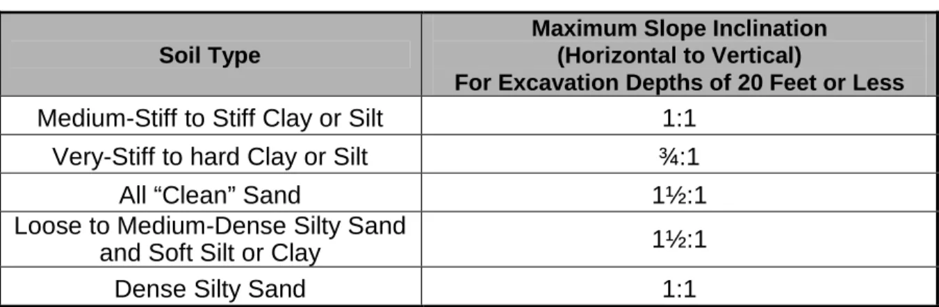
drywell would be expanded to accommodate installation of OSHA approved standard stairs, new pumps, improved operations and maintenance, and optimize sequenced construction of the station. The drywell and wetwell would be expanded by approximately 6 feet to the south and the drywell would be expanded 3 feet to the east. The footprint of the expanded drywell, including the access stairs, is approximately 25-feet by 18- feet. The extension of the subgrade facilities to the south and east will encroach on the existing electrical facilities and the potable water line, which would each need to be relocated.
All of the existing above grade structure would remain in place and a monorail would be installed and extended through the south wall to facilitate pump and valve removal for
maintenance. A new door in the south wall would allow pumps and valves to be moved out of the building. The installed monorails would require a minimum capacity of 1,530 lbs to lift the pumps. A second monorail would be installed at the intermediate floor to lift valves and transport them to the larger pump hatch in the upper floor. The changes to the existing building will require structural modifications to bring the facility up to compliance with the 2010 California Building Code (CBC). The subgrade structure will require significant upgrades to comply with the CBC.
Each pump suction pipe would be 16-inch diameter and extend through the wall into the wetwell with a suction bell. Each pump discharge would include a new isolation plug valve and check valve. No changes or improvements will be required to the influent 36-inch gravity sewer as the inlet into the structure would remain at its current location, however the influent manhole on the site will be rehabilitated. The new magnetic flow meter would be installed on the force main discharge and include two 20-inch x 16-inch reducers and one 16-inch plug valve before tying into the existing 20-inch diameter force main. Five pipe diameters upstream and three pipe diameters downstream of straight length of the flow meter will be provided. The vault would include a sump pump to collect and discharge any drainage collected from the vault.
The proposed expansion of the below grade structures will require relocation of the electrical service lateral. The existing service will however be retained and reconnected to the MID transformer. Standby power will be used to operate the station during this brief reconnection period. The relatively confined spaces within the existing electrical room will require the new MCC and related equipment to be located within the small room adjacent to the existing electrical room, or should space constraints be encountered, within the existing space and the existing MCC and related equipment will be removed after bypass pumping is in place and operational. The new equipment will then be connected to the new pumping systems and fully tested before removal of bypass pumping systems.
Preliminary Design Report
! " # $ %%&%&%%' ( ) $ *+ %%
Alternative 1 Construction Sequencing
In order to construct the new lift station a detailed construction sequencing plan will be
required. It is envisioned that portions of the new wetwell and drywell will be completed while the lift station remains in service by following the construction sequencing plan below.
Relocate any required buried utilities, including electrical. Construct drywell and wetwell below grade additions. House new MCC and related equipment in existing storage room.
Install Pump No. 4 and temporary submersible pump to serve as standby for Pump No. 4 during dry weather installation of Pumps No. 1, 2, and 3.
Connect to forcemain and new wetwell addition.
Use Pump No. 4 and emergency bypass pumping to reliably pump flows. This task must be done during the dry weather season for lower flows.
Complete remaining critical work including the installation of the remaining pumps and the rehabilitation of the wetwell.
Test remodeled lift station civil, mechanical, electrical and instrumentation facilities. Place remodeled lift station into service.
Alternative 1 Advantages and Disadvantages
' % & % & &
Advantages Disadvantages
Alleviates current pump station deficiencies. Difficult/risky construction including extensive bypass pumping operations.
No modifications required to influent gravity sewers. Long construction period. Resolves all station deficiencies and meets design
criteria.
Requires reuse of existing wetwell including structural and corrosion rehabilitation.
Includes standard stairs for maintenance access. Reuse of existing building with significant modifications results in Code compliance upgrades.
New pumps with reliable capacity. Significant and costly structural modifications required to existing lift station drywell and wetwell.
Openings above pumps and overhead monorail crane for access.
No self-cleaning wetwell.
New forcemain header. Relocation of and impact to existing utilities. Rehabilitated wetwell and influent manhole. Highest cost alternative.
Increased capacity to meet projected flows. Limited space for the three pumps in existing drypit.
Cost Estimate
The estimated cost of Alternative 1 is $2,780,000. An itemized breakdown of this cost is presented below.
Preliminary Design Report
! " # $ %%&%&%%' ( ) $ *+ %%
!
( % &
ITEM QUANTITY UNITS UNIT COST TOTAL COST
Mobilization/Demobilization 5% LS $69,350 $69,350 Demolition/Abandonment of Existing Facilities 1 LS $50,000 $50,000 Relocation of Existing Electrical and Water Utility 1 LS $50,000 $50,000 Construction Sequencing and Constraints 1 LS $100,000 $100,000 Dry/Wetwell Excavation/Backfill 400 CY $75 $30,000 Pipe Trench Excavation/Backfill 150 CY $75 $11,250
Shoring 4250 SF $50 $212,500
Miscellaneous Formwork 1 LS $25,000 $25,000
Dewatering 1 LS $30,000 $30,000
Pump Station Concrete 165 CY $1,000 $165,000
Wetwell Grating 1 LS $25,000 $25,000
Structural Rehab and Wetwell Coating 1 LS $25,000 $25,000 Bypass Pumping System and Operation 1 LS $100,000 $100,000 Asphalt Pavement Repair 1 LS $7,500 $7,500 Drypit Submersible Pumps 4 EA $20,000 $80,000 Flow Meter Vault incl. Hatch 1 LS $20,000 $20,000
Vault Sump Pump 1 EA $500 $500
Pump Suction Piping and Bells 1 LS $30,000 $30,000 16" Suction Plug Valves 4 EA $12,000 $48,000
16" Flow Meter 1 EA $20,000 $20,000
20" x 16" Reducer (DI) 2 EA $1,500 $3,000 20" Ductile Iron Pipe (Forcemain) 35 LF $200 $7,000 16" Ductile Iron Pipe 12 LF $160 $1,920
16" Plug Valve 1 EA $12,000 $12,000
12" Ductile Iron Pipe 110 LF $120 $13,200 12" Swing Check Valve 4 EA $6,000 $24,000
12" Plug Valve 4 EA $9,000 $36,000
36" SS Slide Gate w/ Motor Actuator 1 EA $35,000 $35,000
Supports 1 LS $10,000 $10,000
Misc. Piping, Valves, Fittings, etc. 1 LS $10,000 $10,000 Pipe/System Connections 1 LS $5,000 $5,000 Aluminum Access Stairs 1 LS $20,000 $20,000 Structural Modifications for Code Compliance 1 LS $125,000 $125,000
Monorail/Hoist 1 LS $35,000 $35,000
Identification Devices 1 LS $10,000 $10,000 Painting and Protective Coatings 1 LS $10,000 $10,000
Electrical 1 LS $349,000 $349,000
Preliminary Design Report
! " # $ %%&%&%%' ( ) $ *+ %%
$
ITEM QUANTITY UNITS UNIT COST TOTAL COST
SUBTOTAL $1,387,000
TOTAL $1,878,000
BONDS, INSURANCE, OVERHEAD AND PROFIT 18% $339,000
CONTINGENCY 30% $564,000
TOTAL WITH CONTINGENCY $2,781,000
(
6 7
#
2 8 #
-/
The second option is to rehabilitate the existing lift station for use as a submersible self-cleaning trench-style station, including structural modifications and reconfiguration of the wetwell. The building above the wetwell would be removed and a new concrete roof with pump access hatches would be installed 6” above grade. The lowest portion of the drywell will be abandoned in place (filled with gravel and concrete placed in existing floor openings) and the existing floor above the pump room would be used as an area to house the valves. To facilitate a self cleaning wetwell and efficient operation of the trench style wetwell, a new below grade channelized inlet structure would be constructed to the north of the existing wetwell. The existing 36-inch and 10-inch gravity sewer lines would merge into the inlet structure upstream of the wetwell. The 10-inch sewer will drop inside the structure down to the channel. The gravity system upstream will be isolated from the wetwell with a 36-inch motor operated stainless steel slide gate.
Submersible pumps manufactured by Wemco would be provided for this option. Each pump would have a new 12-inch discharge plug valve and check valve located inside the existing pump room prior to the 20-inch force main header. This area would be modified to allow support of the discharge pipes and provide access for maintenance. Access could be via the existing steep stairs or new access stairs could be provided similar to Alternative 1. The cost estimate and site plan prepared reflect the re-use of the existing stairs. The removal of the valves would be through new access hatched in the floor. A new 16-inch magnetic flow meter in a precast concrete vault would be installed on the discharge force main. Based on
preliminary layouts, the required five diameter upstream and three diameter downstream straight lengths can be maintained. The vault would include a sump pump to collect and discharge any drainage collected from the vault. A 16-inch plug valve will also be provided downstream of the flow meter to isolate the lift station.
Due to the site constraints and the locations of above grade infrastructure, the City’s boom truck will not be able to be used directly for pump and valve removal. A monorail is recommended to move the pumps to a location where the boom truck could reach the
equipment. The installed monorail would require a minimum capacity of 3,060 lbs to lift the pumps. New access hatches would be installed over the valves for removal. A monorail would be installed in the building and extended through the south wall to facilitate valve removal. The valves would be moved out of the building through a new door in the south wall.
Preliminary Design Report
! " # $ %%&%&%%' ( ) $ *+ %%
&
The changes to the existing building will require structural modifications to bring the facility up to compliance with the 2010 California Building Code (CBC). The subgrade structure will require significant upgrades to comply with the CBC.
Alternative 2 Construction Sequencing
Modifications to the existing wetwell structure would be provided, including a new west wall and a concrete “ogee” ramp. The existing station along with the 36-inch and 10-inch gravity sewers can remain in operation while the new inlet structure is constructed. The inlet structure can be constructed around the existing gravity sewers and during the transition to the new station operation these pipes can be demolished and redirected into the new wetwell. In order to complete structural rehabilitation, coating work, modifications inside the existing wetwell, and installation of new pumps and piping, a bypass pumping system will be required. It is possible that piping inside the existing pump room can be completed while the lift station remains in service. Once the substructure expansion is completed, pump operation can be shut down and temporary pumping can commence while the connections are made.
Bypass pumping will be significant and the existing lift station flows must be bypassed around the pump station during an entire dry weather season to complete the work. Since surcharging of the existing sewers is not possible, it is envisioned that a temporary submersible pump structure would be constructed around the existing 36-inch gravity sewer onsite to facilitate a deep temporary wetwell for bypass pumping. A portion of the 36-inch sewer will need to be removed and later replaced.
The new MCC and related equipment will be installed within the existing small room adjacent to the electrical room, or if space constraints are encountered, the existing MCC and related equipment will be removed after establishment of by-pass pumping. The new MCC and related equipment will then be installed in place of the existing equipment and controls.
Alternative 2 Advantages and Disadvantages
) % & % & &
Advantages Disadvantages
Self-cleaning wetwell. Wetwell rehabilitation and long duration of bypass pumping system required. No new valve vault required. Modifications required to influent gravity sewer.
No need for personnel to enter wetwell Structural modifications required to lift station for Code compliance. Rehabilitated influent manhole. Monorail needed for valve removal.
Meets project flow requirements Maintains use of steep existing stairs. Modified wetwell without plastic lining.
Preliminary Design Report
! " # $ %%&%&%%' ( ) $ *+ %%
0
Cost Estimate
The estimated cost of Alternative 2 is $2,450,000. An itemized breakdown of this cost is presented below.
* % &
ITEM QUANTITY UNITS UNIT COST TOTAL COST
Mobilization/Demobilization 5% LS $59,900 $59,900 Demolition/Abandonment of Existing Facilities 1 LS $75,000 $75,000 Construction Sequencing and Constraints 1 LS $100,000 $100,000 Wetwell Excavation/Backfill 150 CY $75 $11,250
Dewatering 1 LS $30,000 $30,000
Shoring 3000 SF $50 $150,000
Miscellaneous Formwork 1 LS $25,000 $25,000 Pipe Trench Excavation/Backfill 300 CY $75 $22,500 Wetwell Concrete 135 CY $1,000 $135,000 Bypass Pumping System and Operation 1 LS $100,000 $100,000 Asphalt Pavement Repair 1 LS $5,000 $5,000 Submersible Pumps 4 EA $20,000 $80,000 Flow Meter Vault incl. Hatch 1 LS $20,000 $20,000
Vault Sump Pump 2 EA $500 $1,000
16" Flow Meter 1 EA $20,000 $20,000 20" x 16" Reducer (DI) 2 EA $1,500 $3,000 20" Ductile Iron Pipe (Forcemain) 35 LF $200 $7,000 16" Ductile Iron Pipe 12 LF $160 $1,920 16" Plug Valve 1 EA $12,000 $12,000 12" Ductile Iron Pipe 130 LF $120 $15,600 12" Swing Check Valve 4 EA $6,000 $24,000 12" Plug Valve 4 EA $9,000 $36,000 36" Gravity Sewer 12 LF $360 $4,320 36" SS Slide Gate w/ Motor Actuator 1 EA $35,000 $35,000
Supports 1 LS $10,000 $10,000
Misc. Piping, Valves, Fittings, etc. 1 LS $15,000 $15,000 Pipe/System Connections 1 LS $10,000 $10,000 Structural Modifications for Code Compliance 1 LS $100,000 $100,000
Monorail/Hoist 1 LS $35,000 $35,000
Identification Devices 1 LS $10,000 $10,000 Painting and Protective Coatings 1 LS $20,000 $20,000
Baffles 1 LS $10,000 $10,000
Access Hatches 4 EA $2,000 $8,000
Core Drilling 1 LS $10,000 $10,000
Preliminary Design Report
! " # $ %%&%&%%' ( ) $ *+ %%
4
ITEM QUANTITY UNITS UNIT COST TOTAL COST
Wetwell and Dry Well Ventilation System 1 LS $4,000 $4,000 Miscellaneous Civil Construction 1 LS $20,000 $20,000 Miscellaneous Architectural Construction 1 LS $10,000 $10,000
Electrical 1 LS $311,000 $311,000 Controls 1 LS $72,000 $72,000 SUBTOTAL $1,198,000 TOTAL $1,656,000
BONDS, INSURANCE, OVERHEAD AND
PROFIT 18% $299,000
CONTINGENCY 30% $497,000
TOTAL WITH CONTINGENCY $2,452,000
(
6 9
7
#
2 8 #
Alternative 3 at Emerald Lift Station includes replacing the existing lift station with a new submersible self-cleaning trench style type lift station. The new trench style lift station would be located at the west side of the existing site. Following construction of the new wetwell and successful testing of the new facilities, the wetwell would be abandoned in place and filled with gravel. The below-grade areas of the drywell will be abandoned in place (filled with gravel and concrete placed in existing floor openings), and the above grade drywell and existing wetwell entrance portion of the building will be reused for electrical equipment.
The lift station would be self cleaning with submersible Wemco pumps and an “ogee” ramp would be constructed. Modifications to the influent gravity sewer would include a new 36-inch pipe and a new 72-inch diameter manhole to intercept the existing 10-inch gravity sewer just north of the proposed location of the lift station.
Discharge piping and 12-inch plug valves and swing check valves, dedicated for each pump, will be located in a valve vault with removable checkered plate. The dedicated discharge lines would connect to a 20-inch force main which would include two 20-inch x 16-inch reducers, a 16-inch magnetic flow meter, and a 16-inch plug valve. The flow meter would be installed in a precast concrete vault and the plug valve would allow the lift station to be isolated from the system. The vault would include a sump pump to collect and discharge any drainage collected from the vault.
Alternative 3 does not require the need for any bypass pumping system or risky construction sequencing and constraints. The system can be completed aside from the connections to the existing forcemain and gravity sewers which will reduce overall construction risks and costs.
Preliminary Design Report
! " # $ %%&%&%%' ( ) $ *+ %%
5
Once the construction is complete, the final connections can be made and the lift station can begin normal operation.
Due to the site constraints and the locations of above grade infrastructure, the City’s boom truck will not be able to be used for pump removal. In order to remove the pumps for maintenance, a monorail and hoist is recommended. The City’s boom truck could be used to remove the valves from the valve vault.
Alternative 3 Construction Sequencing
The preliminary construction sequencing plan for Alternative 3 is as follows: Re-route existing 10-inch gravity sewer and odor control bed piping.
Construct new submersible lift station, 36-inch gravity sewer, and 20-inch force main while existing lift station remains in operation.
Connect both lift stations to existing force main.
Test new lift station while using existing lift station as backup.
Decommission existing lift station and perform demolition of below-grade and above- grade wetwell.
Alternative 3 Advantages and Disadvantages
+ % & " % & &
Advantages Disadvantages
Meets design criteria and alleviates current lift station deficiencies.
Significant demolition and lack of reuse of existing infrastructure.
No bypass pumping or risky construction sequencing and constraints. Existing station can remain in operation.
Modifications required to influent gravity sewer.
New, plastic lined self-cleaning wetwell. Lowers risk and less construction time than with rehabilitation options.
Cost competitive with full rehabilitation options. Rehabilitated influent manhole.
New lift station with no code compliant requirements as required with the use of existing facilities and no rehabilitation of existing wetwell.
Lowest cost alternative
Preliminary Design Report
! " # $ %%&%&%%' ( ) $ *+ %%
Cost Estimate
The estimated cost of Alternative 3 is $2,070,000. An itemized breakdown of this cost is presented below.
- % & "
ITEM QUANTITY UNITS UNIT COST TOTAL COST
Mobilization/Demobilization 5% LS $48,400 $48,400 Demolition/Abandonment of Existing Facilities 1 LS $100,000 $100,000 Wetwell Excavation/Backfill 400 CY $75 $30,000 Pipe Trench Excavation/Backfill 600 CY $75 $45,000
Dewatering 1 LS $30,000 $30,000
Shoring 1800 SF $50 $90,000
Wetwell Concrete 200 LS $1,000 $200,000
New Manhole 1 EA $15,000 $15,000
Asphalt Pavement Repair 1 LS $5,000 $5,000
Submersible Pumps 4 EA $20,000 $80,000
Flow Meter Vault incl. Hatch 1 LS $20,000 $20,000 Valve Vault with Access Hatches 1 LS $25,000 $25,000
Vault Sump Pump 1 EA $500 $500
16" Flow Meter 1 EA $20,000 $20,000
20" x 16" Reducer (DI) 2 EA $1,500 $3,000 20" Ductile Iron Pipe 40 LF $200 $8,000 16" Ductile Iron Pipe 12 LF $160 $1,920
16" Plug Valve 1 EA $12,000 $12,000
12" Ductile Iron Pipe 110 LF $120 $13,200 12" Swing Check Valve 4 EA $6,000 $24,000
12" Plug Valve 4 EA $9,000 $36,000
Supports 1 LS $10,000 $10,000
36" Gravity Sewer 50 LF $360 $18,000 36" SS Slide Gate w/ Motor Actuator 1 EA $35,000 $35,000 Misc. Piping, Valves, Fittings, etc. 1 LS $20,000 $20,000 Pipe/System Connections 1 LS $10,000 $10,000
Monorail/Hoist 1 EA $35,000 $35,000
Identification Devices 1 LS $10,000 $10,000 Painting and Protective Coatings 1 LS $20,000 $20,000
Baffles 1 LS $10,000 $10,000
Pump Station Plastic Liner 1800 SF $5 $9,000
Access Hatches 4 EA $2,000 $8,000
Ventilation System 1 LS $4,000 $4,000
Preliminary Design Report
! " # $ %%&%&%%' ( ) $ *+ %%
!
ITEM QUANTITY UNITS UNIT COST TOTAL COST
Electrical 1 LS $313,000 $313,000 Controls 1 LS $70,000 $70,000 SUBTOTAL $968,000 TOTAL $1,400,000
BONDS, INSURANCE, OVERHEAD AND PROFIT 18% $252,000
CONTINGENCY 30% $420,000
TOTAL WITH CONTINGENCY $2,072,000
(
#
Based on the analysis of the three alternatives for the rehabilitation of Emerald Lift Station a matrix analysis is presented in Table 10. The ranking provides a score between 0 and 10, with a higher number indicating a more favorable outcome.
. ! % C o s t C o n s tru c ta b il it y E a s e o f O p e ra ti o n a n d M a in te n a n c e S tru c tu ra l M o d if ic a ti o n s C o n s tru c ti o n D u ra ti o n F lo w B y p a s s in g D u ra ti o n R is k d u ri n g C o n s tru c ti o n T OT A L Alternative 1 6 4 5 4 4 6 5 34 Alternative 2 7 6 7 6 6 4 6 42 Alternative 3 8 9 8 10 8 10 9 62
Based on the preliminary analysis Alternative 3 is the recommended alternative for Emerald Lift Station.
Preliminary Design Report
! " # $ %%&%&%%' ( ) $ *+ %%
$
!
"
8
(
"
:
Based on the preliminary alternatives analysis and discussions with the City, Alternative 3 as previously identified is the preferred alternative. HDR worked with the City to further develop and refine Alternative 3 which is presented in this chapter. Alternative 3 at Emerald Lift Station includes replacing the existing lift station with a new submersible self-cleaning trench style type lift station. The new trench style lift station will be located at the west side of the existing site. Following construction of the new lift station and successful testing of the new facilities, the existing wetwell will be abandoned in place and filled with controlled density fill (CDF). The below-grade areas of the drywell will be abandoned in place (filled with CDF and concrete placed within the existing floor openings at grade), and the above grade drywell including the existing maintenance room will be reused for electrical equipment and restroom facilities. The above grade portion of the wetwell entrance will be demolished to three feet below grade to facilitate site access to the new lift station.
The firm capacity of the Emerald lift station shall be designed for 3,100 gpm. Per direction at the project kickoff meeting, the station will be designed to reliably pump 3,100 gpm (4.5 mgd) with permanent standby power. In addition, the station shall be designed to pump 6,800 gpm (9.8 mgd) with all units operating, no standby power. It was originally envisioned that a self-priming diesel-driven portable pump would make up the difference between 6,800 gpm and all installed pumps (duty and standby). Upon additional information provided by the City, the maximum surcharge level within the wetwell/sewer at the Emerald site shall be no higher than an elevation 70.55 feet to prevent sewer backups. It was determined that use of an engine-driven pump for this application was not recommended. To meet the flow conditions identified for the station, four equally sized pumps with a total pumping capacity of 6,800 gpm will be installed.
City staff has indicated that Wemco pumps shall be used for the submersible pumps with the last pump having a Wemco pre-rotation basin installed. The pump specifics presented below have been provided by Wemco. Between the alternatives analysis and the preferred alternative phase the hydraulic analysis was further defined to more accurately select the correct pump for the application.
#
Criteria Value
Firm Capacity 3,100 gpm
Total Capacity (all 4 pumps) 6,800 gpm Pump Capacity, each
(w/ four pumps operating) 1,700± 1
gpm
Total Dynamic Head at 3,100 gpm 20 ft Total Dynamic Head at 6,800 gpm 28 ft Pump Suction Flange 10 in Pump Discharge Flange 10 in
Preliminary Design Report
! " # $ %%&%&%%' ( ) $ *+ %%
&
Criteria Value
Motor Speed 1,200 rpm
Pump No. 1 Maximum Speed 1,150 rpm Pump No. 2 – 4 Speed, maximum (limited) 1,060 rpm
Pump Weight 1,530 lb
Unseating Pump Weight 3,060 lb
1. Pump capacity for each pump will increase with fewer pumps in operation.
The pump selected is a Wemco Model F10K-HD with a 30 hp motor. The motor is Wemco Model FE4A6 which will be rated for a maximum speed of 1200 rpm. When a single pump is running, the motor speed will be a maximum of 1150 rpm. Pump No. 1 will run at a maximum speed of 1150 rpm to meet the low flow conditions and create more seamless operation with Pump No. 2. In order to optimize the operation to meet the design conditions when more than one pump is running, the motor speed of multiple running pumps will be limited to 1060 rpm. Minimum motor speed for all pumps will be limited to 850 rpm, which is the lowest speed curve provided on the Wemco Model F10K-HD pump as shown in Appendix B.
Reliability and Redundancy
Reliability and redundancy minimizes the probability of wastewater overflows at the pumping station and within its service area. Any backups or failures of the pump station may result in wastewater backflow into neighboring residential basements. Reliable pumping capacity is defined by the City as the ability to pump the peak flow of 3,100 gpm with the largest pump out
of service and without relying on Modesto Irrigation District (MID) for power. The station's
reliability will also be improved in other areas as part of this project to reduce call-outs and unscheduled maintenance. Pumping units and all critical auxiliary equipment will meet reliability requirements.
The permanent standby generator is capable of operating two of the submersible pumps at full speed. The fuel storage tank with a capacity of 170 gallons is sufficient to run the two pumps for 24 continuous hours at full load. A redundant submersible pump, motor, and VFD will be called if one of the duty pumps fails.
;
Inlet Gravity Sewer Sizing
The inlet gravity sewer was sized to match the existing influent 36-inch diameter line.
However, calculations were completed to ensure that the inlet gravity sewer pipe is sufficiently sized handle the PWWF plus the West Trunk Relief Flows of 6,800 gpm using Manning’s Equation for full flowing circular channels. Table 12 below summarizes the Manning’s Equation calculations and results:
Manning’s Equation: Q = 1.49 / n * A * R2/3 * S1/2
Where:
Preliminary Design Report
! " # $ %%&%&%%' ( ) $ *+ %%
,
n = Manning’s Roughness Coefficient (unitless) d = Pipe Diameter
A = Cross-Sectional Area of pipe (in ft2) R = Hydraulic Radius (in ft)
S = Slope of pipe (ft/ft) D= Flow Depth
/ 0
Inputs Value Note
Diameter (d) 36 in Inside Pipe Diameter Manning’s Roughness Coefficient (n) .013 Typical for Ductile Iron Pipe Slope (S) 0.005 ft/ft Set to match existing
Calculated Values Value Note
Cross Sectional Area (A) 7.07 ft2 A = pi * (d/2)2 Depth at Design Flow (D) 14 in
Hydraulic Radius (R) at Design Flow 0.63 ft
Results Value Note
Maximum Flow Rate (Q) per Manning’s Equation
with the inputs listed above 17,710 gpm
Converted from cfs to gpm (pipe flowing approximately 70% full)
As mentioned, the influent pipe was sized at 36-inches to match the existing influent into the pump station. Per the City’s Master Plan the new pipe shall be sized to flow at maximum 70% full. At the given slope a 24-inch or 30-inch diameter pipe would have a maximum flow capacity (70% full) of approximately 6,010 gpm or 10,890 gpm, respectively. The 24-inch diameter pipe more closely reflects the maximum design condition; however, the velocity at this flow is approximately 5.7 feet per second through a 24-inch pipe. Given the close proximity of the lift station to the upstream manhole, and the change in flow direction, the 36-inch diameter pipe presents the best selection which flows at approximately 39% full at the maximum capacity.
Effluent Force Main Sizing
A majority of the existing effluent force main will be reused in this project. However, portions on the pump station site will be removed and an additional section near the discharge manhole will be replaced. The existing 20-inch force main runs approximately 150 linear feet from the site fence under the MID canal to the discharge manhole in Emerald Avenue. An additional 25 linear feet is located within the site which will be removed during construction and replaced with an alignment from the new lift station. During construction, a 10 foot section of 20-inch force main that connects to the discharge manhole will be removed and replaced.
The rim of the discharge manhole is flush with the street at elevation 86.05± feet. The 20-inch forcemain from the Emerald Lift Station to the northwest enters the manhole at an invert elevation of 80.05± feet. A 36-inch gravity pipe exits the discharge manhole at an invert elevation of 79.33± feet and travels south within Emerald Avenue.
Preliminary Design Report
! " # $ %%&%&%%' ( ) $ *+ %%
0
Lift Station Pump and System Curves
The system curve for the station is calculated by combining static and dynamic pressure head losses in the piping from the submersible pumps in the new wet well to the discharge manhole southeast of the site in Emerald Avenue.
Based on the influent elevation and the required operating elevations of each pump which will be discussed, the wet well invert elevation was determined. The static elevations have been used with the dynamic losses seen through the onsite valves, flow meter, and piping to determine the system curve as shown in Figure 6. The pump selection shown in Table 11 is based on the system curve presented.
Since the pumps will be operated on variable frequency drives (VFDs) reduced speed pump curves are also provided. This set of curves shows that at lower flows, the lift station will continue to operate properly.
Significant changes are required to accommodate the construction of the new Emerald Lift Station. The above grade portion of the existing drywell (electrical room and maintenance room) will be utilized for the installation of new electrical equipment and for the new restroom facilities. To facilitate construction, the City has indicated that the SCADA panel will be relocated prior to construction. A large portion of the existing wall between the electrical room and maintenance room will be removed to aid construction as shown in Figure 7. The wall will be removed and a structural beam installed below the roof to provide approximately 8.0 feet of headroom above the finished floor as shown in Figure 7. This will allow the electrical panels to be installed on the southern wall and a new double door to be installed in the existing west wall of the pump station. All existing electrical panels removed will be salvaged and returned to the City.
To improve site access the City requested the ability to drive over the northeast portion of the existing wetwell (which is currently located slightly above grade). The top of the below grade wetwell in this location will be removed and the existing below-grade portion of the below grade areas will be abandoned and filled with controlled density fill (CDF) to avoid
maintaining ventilation and drainage below grade. The wetwell will be abandoned and the top 3 feet of the above grade wetwell structure will be demolished and paved over. This includes the existing wetwell access stairs. CDF will be used to backfill all of the below grade areas as shown in Figure 9. Per the structural engineer, the rigid backfill shall be installed in a manner so that full support of the structure to remain above the wetwell will be achieved. Once this is complete, the portions of the walls and slabs noted can be removed.
Additional subgrade demolition will be required with the removal or abandonment of portions of the existing gravity sewer and forcemain. As shown in Figure 7, the existing 36-inch and 10-inch gravity sewers will be plugged with concrete, filled with CDF, and abandoned in place. The pipe will be left in place due to the burial depth and the associated cost of removal. The
! "#$
%
& ! " # ! " $ # % &'()* & %+" , ' # %' - ! . /0$ * 1 - 2 # %' . /0$ * 34 3 - ! 1 - 2 # %' . /0$ * 34 3 - ! 5' 1 2 - &( " "66 61 - 2 # %' . /0$ * 34 3 - ! 5' 1 2 - &( " "66 61 - 2 # %' . /0$ * 34 3 - ! 5' 1 2 - &( " "66 61 - 2 # %' . /0$ * - ! 1 - 2 # %' . /0$ * 34 3 - ! 1 - 2 # %' . /0$ * 34 3 - ! 5' 1 2 - &( " "66 61 - 2 # %' . /0$ * 34 3 - ! 5' 1 2 - &( " "66 61 - 2 # %' . /0$ * 34 3 - ! 5' 1 2 - &( " "66 61 - 2Preliminary Design Report
! " # $ %%&%&%%' ( ) $ *+ %%
!
The west side of the site is bordered by an existing odor control bed which consists of a series of 6-inch perforated PVC pipe embedded in a 2 foot layer of aggregate. Portions of this system must be temporarily modified to allow construction of the new lift station and the re-routing of the 10-inch gravity sewer. At construction completion, this system must be restored.
A detailed construction sequencing plan is included in Chapter 5. The existing electrical equipment in the building will remain in service until the new lift station is operational.
#
(
The site is currently accessed via two driveways from Emerald Avenue on the east side of the site as shown on Figure 10. The driveways and existing rolling gates will remain in place and no improvements will be made. The site is located adjacent to a residence on the north and an MID canal on the south. The Contractor will be required to work within the site and conform to construction sequencing and constraints throughout the construction as discussed in Chapter 5. The existing site is currently paved with AC paving. The site demolition work will include the removal of all paving. At project completion, the entire Emerald Lift Station site currently paved will be repaved with concrete.
The site currently drains within the site with stormwater flowing to the dirt or landscaped areas around the site. The new concrete paving will be designed to maintain drainage to adjacent dirt and landscaped areas. Work will be required adjacent to the existing soil bed odor control system, including temporary relocation of some of the piping to allow for construction of the lift station and 10-inch gravity sewer. At project completion, the Contractor will be required to reinstall all piping and restore to the soil bed to its preconstruction operating condition. The flow meter vault and valve vault will be constructed with H20 rated materials and be configured so that City operations can drive over them.
7
#
2 8 #
The existing Emerald Lift Station will be replaced with a new submersible self-cleaning trench style type lift station. The new trench style lift station will be located at the northwest corner of the existing site as shown in Figure 10. The pump station will be located to optimize vacuum truck and site access. Following construction of the new lift station and successful testing of the new facilities, the existing wetwell will be abandoned in place and filled with CDF. The below-grade areas of the drywell will be abandoned in place (filled with CDF and concrete placed in existing floor openings), and the above grade drywell, including the existing maintenance and electrical rooms, will be reused for electrical equipment and restroom facilities. The existing above grade portion of the wet well (i.e. stairs) will be demolished to 3 feet below grade and the area paved with concrete.
Preliminary Design Report
! " # $ %%&%&%%' ( ) $ *+ %%
&
The new trench style lift station will measure approximately 23 feet long by 8 feet wide. The lift station will be self cleaning with submersible Wemco pumps and an “ogee” ramp.
Modifications to the influent gravity sewer will include a new 36-inch pipe and a new 72-inch diameter manhole to intercept the existing 10-inch gravity sewer just north of the proposed location of the lift station.
Figure 10 shows the lift station plan view and Figure 11 shows a section view of the lift station. The goal of the “ogee” ramp is to enhance the cleaning of the pump station in combination with a pre-rotation basin. To fully utilize the “ogee” ramp, the 36-inch slide gate on the influent will be closed to build up flow in the 36-inch gravity sewer. When the slide gate opens the lift station will see a surge of flow that will sweep any settled material to the pre-rotation basin at the far end of the trench. A smooth transition of the ogee ramp to the lift station floor is required to avoid the creation of aerosols.
The pre-rotation basin will be installed at the far end of the lift station, away from the station’s inlet. The basin will be set in a recess in the floor to enhance the cleaning operations of the station. Only one of the pumps will be installed in the pre-rotation basin. The other three pumps will be installed at a higher elevation than the fourth pump. However, the pump fittings, including suction bells and guide shoes, will be interchangeable between all four pumps. Since the fourth pump is set at a lower elevation, the pump will have a different off set point than the other three pumps. The prerotation pump could be started when the water level is just 18 inches above the main wet well floor, which with the 18 inch depth, provides the minimum 36 inches of submergence. All other pumps will be shut off when the water level reaches 18 inches above the floor. The pumps will not operate correctly if the water level drops below this elevation.
A concrete pump washdown area with a drain will be constructed on the south side of the wetwell so that washwater from pump cleaning will drain back into the wetwell. The area will be sloped to a center drain and the west side of the area will be contained with a 6-inch high concrete curb. No curb will be placed on the east side of the area to accommodate truck access. The floor drain will be covered with a removable grate and the invert of the discharge into the wet well will be significantly above the high water level to eliminate any potential backflow conditions. To accommodate cleaning and maintenance, a hose bibb will be installed adjacent to the area and connected to the existing onsite water line. As shown in Figure 10, the
washdown area has been configured so that a maintenance truck can pull into the area and allow the monorail hoist to set a removed pump in the truck bed.
Lift Station Odor Control
To reduce onsite odors and prevent complaints from the surrounding residents, an odor control fan will be located adjacent to the standby generator to draw air from the wetwell and discharge it to the existing soil bed system. An 8-inch diameter FRP pipe will be hard piped from the wetwell to the fan. The pipe will penetrate the wet well wall and turn down to terminate 12-inches above the grating. A backup standby fan will not be provided. The existing soil bed