HEDS-9000/9100 Two Channel Optical Incremental Encoder Modules. Features. Applications
Full text
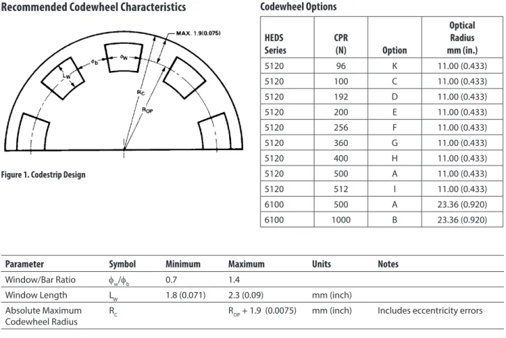
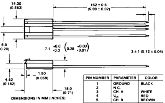
Figure

Related documents
In order to assess whether collective treatment improves the social support for post-stroke patients, the original treatment protocol was modified (individual therapy for six
Based on the earlier statement that local residents’ perceptions and attitude toward tourism contribute to the success of tourism development in a destination, the
19% serve a county. Fourteen per cent of the centers provide service for adjoining states in addition to the states in which they are located; usually these adjoining states have
The objective of this study was to develop Fourier transform infrared (FTIR) spectroscopy in combination with multivariate calibration of partial least square (PLS) and
Histological examination of rabbit globes following this mode of cryo- application also showed a number of undesirable side effects, pri- marily disruption of the
Field experiments were conducted at Ebonyi State University Research Farm during 2009 and 2010 farming seasons to evaluate the effect of intercropping maize with
54964.0 ELECTRICAL ENGINEERING 55232.0 COMPUTER ENGINEERING 55249.0 CIVIL ENGINEERING 55299.0 MECHANICAL ENGINEERING 55408.0 INFORMATION TECHNOLOGY Page 8 of 130 All Ranks
O RG ., http://www.wipo.int/amc/en/domains/search (last visited Apr. The domain names at issue in the relevant UDRP decisions target different trademark owners. Consequently, even
