FLOW ALARMS
NOTE: Installation, operation and cleaning instructions for the basic flow meter cartridge can be found in the first section of this manual. The following instruc-tions are specifically for meters with electrical switches for flow alarms.
General Information
Lake’s Flow Alarms are typically used to make or break a set of electrical contacts to signal a limit setting. They may be used to turn on a warning light, sound a bell or horn, or even to shut down a process. The switches on the alarm can be configured to open or close a contact for an increasing or decreasing set point. Single switch units are built to switch in the lower 2/3 of the scale. For units that need to switch in the upper 2/3 of the scale, please contact the factory.
Overview
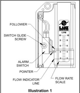
Illustration 1shows the primary mechanism for a single-switch flow alarm. Dual-switch flow alarms contain two sets of these same com-ponents, but have a slightly different electrical wiring diagram (Wiring to the DIN connector is described on page 24.) The factory default configuration for the alarm switch is for decreasing flow, as shown in Illustration 1. Dual alarm units contain one additional switch config-ured for increasing flow. If an increasing flow alarm is desired, it should be specified when the unit is ordered.
The followermoves in unison with an orifice plate inside of the unit’s pressure vessel via a magnetic coupling in order to indicate flow rate. As the follower moves with changes in flow rate, the flow rate is determined by relating the position of the flow indica-tor lineto the increments on the flow rate scale.
Illustration 1 FOLLOWER POINTER SWITCH GLIDE SCREW ALARM SWITCH FLOW INDICATOR LINE FLOW RATE SCALE
The pointerindicates the set point for the alarm switch. In Illustration 1, the switch will be actuated at all flow rates below 4 GPM. To change the set point, simply loosen the switch glide screwone (1) turn and slide the switch to the desired position along the flow rate scale. When the pointeris pointing to the desired flow rate, re-tighten the switch glide screw.
Switches
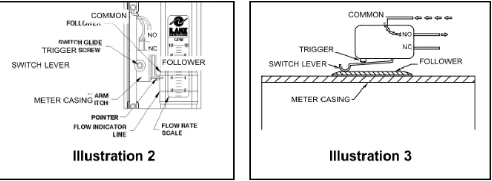
The switch is a simulated roller, lever operated low force microswitch. The specifications for this switch are listed on page 24. The switch is actuated when movement of the follower causes the switch lever to be lifted. In Illustration 2, the switch has not yet been actuated, and the electrical circuit is through the normally closed (NC) contact. Illustration 3shows the switch after it has been actuated. In this sce-nario, the electrical circuit is through the normally open (NO) contact.
Precautions
n Be certain to properly ground the unit via the ground (G) pin located on the unit’s din connector.
n In order to avoid accidentally removing the switch glide screw, never loosen it by more than one or two turns. This screw can be difficult to replace if accidentally removed.
n Avoid over tightening the switch glide screw.
n When the switch adjustments are complete, make certain that the wires that are attached to the switch have not been moved into a location that will interfere with the follower or the switch lever.
n Do not make any modifications to the unit’s internal wiring.
TRIGGER COMMON
SWITCH LEVER FOLLOWER METER CASING
NO NC
Illustration 2 Illustration 3
TRIGGER COMMON
SWITCH LEVER FOLLOWER METER CASING
NO NC
Switches Specifications
Type Form C, dry contact
UL/CSA Rating 10 & 1/4 hp, 125 or 250 VAC
1/2 A, 125 VDC & 1/4A, 250 VDC 3A, 125 VAC “L” lamp load
Mechanical Life >10,000,000 cycles
Actuating Mechanical Simulated roller, lever operated, low force
Connectors 3/16" tab
Double Break Switch (Special) Form Z - 10A &1/2hp, 125/250 VAC
Electrical Connections
Standard Flow Alarmsare pre-wired with 4-pin Hirschmann-type DIN connectors which consist of a male section as shown in Illustration 4and the female section shown
in Illustration 5. To open the female section, first remove the screw, then lift the connector portion out of the casing by inserting the head of a screwdriver into the slot marked for that purpose. Illustration 6 shows the disassembled female section.
Illustration 4
Illustration 6
Illustration 7shows the connections for a standard, single switch Flow Alarm as they are shipped from the factory. The wiring for other types of connections are outlined in the tables below. For additional details, please consult the factory or your authorized Lake distributor. Alternates to the standard
Hirschmann-type DIN connector are available on a custom basis. The Flow Alarm may be outfitted with a variety of different electrical connections including conduit fittings, cable-type connectors and cord grip/pigtail interfaces. Almost any commercially available electrical connector may be used. If an alternate connector is desired, please consult Lake.
Wiring Code: Standard Single Switch
White - Common Terminal #1of DIN
Black - N.C. Contact Terminal #2 of DIN
Red - N.O Contact Terminal #3 of DIN
Green - Enclosure Ground Terminal “G” of DIN
Wiring Code: Dual Switch Alarm
White - Both Common Terminal #1of DIN
Black - Decreasing N.O. Contact Terminal #2 of DIN Red - Increasing N.O. Contact Terminal #3 of DIN Green - Enclosure Ground Terminal “G” of DIN
Illustration 7 GREEN NO NC BLACK WHITE COMMON RED TO ENCLOSURE GROUND
* The load must be within the flow alarm’s and the slave relay’s contact rating. Please see specifications.
NOTES:
_ _ _ _ _ _ _ _ _ _ _ _ _ _ _ _ _ _ _ _ _ _ _ _ _ _ _ _ _ _ _ _ _ _ _ _ _ _ _ _ _ _ _ _ _ _ _ _ _ _ _ _ _ _ _ _ _ _ _ _ _ _ _ _ _ _ _ _ _ _ _ _ _ _ _ _ _ _ _ _ _ _ _ _ _ _ _ _ _ _ _ _ _ _ _ _ _ _ _ _ _ _ _ _ _ _ _ _ _ _ _ _ _ _ _ _ _ _ _ _ _ _ _ _ _ _ _ _ _ _ _ _ _ _ _ _ _ _ _ _ _ _ _ _ _ _ _ _ _ _ _ _ _ _ _ _ _ _ _ _ _ _ _ _ _ _ _ _ _ _ _ _ _ _ _ _ _ _ _ _ _ _ _ _ _ _ _ _ _ _ _ _ _ _ _ _ _ _ _ _ _ _ _ _ _ _ _ _ _ _ _ _ _ _ _ _ _ _ _ _ _ _ _ _ _ _ _ _ _ _ _ _ _ _ _ _ _ _ _ _ _ _ _ _ _ _ _ _ _ _ _ _ _ _ _ _ _ _ _ _ _ _ _ _ _ _ _ _ _ _ _ _ _ _ _ _ _ _ _ _ _ _ _ _ _ _ _ _ _ _ _ _ _ _ _ _ _ _ _ _ _ _ _ _ _ _ _ _ _ _ _ _ _ _ _ _ _ _ _ _ _ _ _ _ _ _ _ _ _ _ _ _ _ _ _ _ _ _ _ _ _ _ _ _ _ _ _ _ _ _ _ _ _ _ _ _ _ _ _ _ _ _ _ _ _ _ _ _ _ _ _ _ _ _ _ _ _ _ _ _ _ _ _ _ _ _ _ _ _ _ _ _ _ _ _ _ _ _ _ _ _ _ _ _ _ _ _ _ _ _ _ _ _ _ _ _ _ _ _ _ _ _ _ _ _ _ _ _ _ _ _ _ _ _ _ _ _ _ _ _ _ _ _ _ _ _ _ _ _ _ _ _ _ _ _ _ _ _ _ _ _ _ _ _ _ _ _ _ _ _ _ _ _ _ _ _ _ _ _ _ _ _ _ _ _ _ _ _ _ _ _ _ _ _ _ _ _ _ _ _ _ _ _ _ _ _ _ _ _ _ _ _ _ _ _ _ _ _ _ _ _ _ _ _ _ _ _ _ _ _ _ _ _ _ _ _ _ _ _ _ _ _ _ _ _ _ _ _ _ _ _ _ _ _ _ _ _ _ _ _ _ _ _ _ _ _ _ _ _ _ _ _ _ _ _ _ _ _ _ _ _ _ _ _ _ _ _ _ _ _ _ _ _ _ _ _ _ _ _ _ _ _ _ _ _ _ _ _ _ _ _ _ _ _ _ _ _ _ _ _ _ _ _ _ _ _ _ _ _ _ _ _ _ _ _ _ _ _ _ _ _ _ _ _ _ _ _ _ _ _ _ _ _ _ _ _ _ _ _ _ _ _ _ _ _ _ _ _ _ _ _ _ _ _ _ _ _ _ _ _ _ _ _ _ _ _ _ _ _ _ _ _ _ _ _ _ _ _ _ _ _ _ _ _ _ _ _ _ _ _ _ _ _ _ _ _ _ _ _ _ _ _ _ _ _ _ _ _ _ _ _ _ _ _ _ _ _ _ _ _ _ _ _ _ _ _ _ _ _ _ _ _ _ _ _ _ _ _ _ _ _ _ _ _ _ _ _ _ _ _ _ _ _ _ _ _ _ _ _ _ _ _ _ _ _ _ _ _ _ _ _ _ _ _ _ _ _ _ _ _ _ _ _ _ _ _ _ _ _ _ _ _ _ _ _ _ _ _ _ _ _ _ _ _ _ _ _ _ _ _ _ _ _ _ _ _ _ _ _ _ _ _ _ _ _ _ _ _ _ _ _ _ _ _ _ _ _ _ _ _ _ _ _ _ _ _ _ _ _ _ _ _ _ _ _ _ _ _ _ _ _ _ _ _ _ _ _ _ _ _ _ _ _ _ _ _ _ _ _ _ _ _ _ _ _ _ _ _ _ _ _ _ _ _ _ _ _ _ _ _ _ _ _ _ _ _ _ _ _ _ _ _ _ _ _ _ _ _ _ _ _ _ _ _ _ _ _ _ _ _ _ _ _ _ _ _ _ _ _ _ _ _ _ _ _ _ _ _ _ _ _ _ _ _ _ _ _ _ _ _ _ _ _ _ _ _ _ _ _ _
For downloadable product manuals,
data sheets and CAD drawings,
visit Lake’s web site today!
www.lakemonitors.com
LAKE MONITORS 8809 INDUSTRIAL DRIVE, FRANKSVILLE, WI 53126 P: (800) 850-6110 (262) 884-9800 F: (262) 884-9810 WWW.LAKEMONITORS.COM