EVALUATING STANDARD AND CUSTOM APPLICATIONS IN IPV6 WITHIN A SIMULATION FRAMEWORK
Brittany Michelle Clore
Thesis submitted to the faculty of the Virginia Polytechnic Institute and State University in partial fulfillment of the requirements for the degree of
Master of Science In
Computer Engineering
Joseph G. Tront, Chair Randolph C. Marchany
C. Jules White
July 30, 2012 Blacksburg, VA
Keywords: IPv6, Simulation, Custom Application, Framework, OPNET
EVALUATING STANDARD AND CUSTOM APPLICATIONS IN IPV6 WITHIN A SIMULATION FRAMEWORK
Brittany Michelle Clore
ABSTRACT
Internet Protocol version 6 (IPv6) is being adopted in networks around the world as the Internet Protocol version 4 (IPv4) addressing space reaches its maximum capacity. Although there are IPv6 applications being developed, there are not many production IPv6 networks in place in which these applications can be deployed. Simulation presents a cost effective alternative to setting up a live test bed of devices to validate specific IPv6 environments before actual physical deployment. OPNET Modeler provides the capability to simulate the IPv6 protocol and System-in-the-Loop, an add-on module, allows for real communication traffic from physical devices to be converted and sent over the simulated network. This research has developed a campus
framework, modeled after the Virginia Tech Blacksburg campus, to verify and validate standard and custom IPv6 applications. Specifically, the framework was used to test MT6D, a custom IPv6 security application developed in the Virginia Tech IT Security Lab (ITSL) as well as test Voice over IP (VoIP) as a somewhat bandwidth demanding benchmarking standard application. The work presented shows that simulation helped to identify potential issues within the
applications and verified the results after fixes were applied. It also reveals challenges and shortcomings of OPNET Modeler’s IPv6 implementation and presents potential solutions to these problems.
iii
ACKNOWLEDGEMENTS
There are several people that have been an integral part of my time at Virginia Tech. They have been instrumental in guiding me through my education, helping through the difficult times and providing needed support.
I would like to thank Dr. Tront for being my committee advisor and guiding my education throughout my time at Virginia Tech. My first college experience sitting in your Intro to
Computer Engineering class made me realize that I made the right choice for school. I know that my graduate experience has been a positive one because of your help and guidance.
I would like to thank Randy for giving me a spot in the lab and providing a wealth of information that could come from no other person. By being around you and the lab, I know that I’ve learned more through osmosis than any other place I could have been. The light hearted spirit of the lab has only come from your example and I hope that it continues to be that way far into the future. I would like the thank Dr. White for being on my committee and willing to deal with all the scheduling changes.
I would like to thank Lt. Colonel Matthew Dunlop for allowing me to be a part of his research. I would not have survived this degree without your help and guidance. You were always willing to teach me about networking skills and protocols that I did not get in my classes and help me through my writing process. I’m glad that we were able to work through all the various
simulation issues to get the results we needed, even if it was by working overnight and through weekends.
I would like to that the undergraduate workers in the lab, particularly Reese and Matt, for helping with VoIP testing. I enjoyed all the fun “nerdy” conversations on code optimization, movies and computers.
My friends deserve great thanks for putting up with me throughout my education. Without my friends in Blacksburg, I would have led a very boring life.
Last but not least, I need to thank my family. Without my parents, I would not be in the place that I am today. There are not enough words to express my deep appreciation for all that they have done for me. My siblings also have helped me through by reminding me to have fun and enjoy the little things.
Romans 8:28 - And we know that all things work together for good to those who love God, to those who are the called according to His purpose.
iv
TABLE OF CONTENTS
Table of Contents ... iv
List of Figures ... vii
List of Tables ... ix
1. Introduction ... 1
2. Background ... 3
2.1 IPv6 ... 3
2.1.1 Addressing ... 3
2.1.2 Header Format Comparison and Flow Labeling Capabilities ... 6
2.1.3 Support for Extensions ... 9
2.1.4 ICMPv6 ... 10
2.1.5 NDP ... 13
2.2 Voice over IP ... 14
2.3 Moving Target IPv6 Defense ... 17
2.4 Chapter Conclusion ... 18
3. OPNET Modeler and the System-in-the-Loop Module ... 19
3.1 OPNET Modeler Overview ... 19
3.2 The System-in-the-Loop Module ... 21
3.3 The Advantages and Disadvantages of OPNET Modeler ... 23
3.4 The Use of Modeler in this Research ... 24
3.5 Chapter Conclusion ... 24
4. Simulation Tools and Related Research ... 26
4.1 Simulation and Emulation Tools ... 26
4.2 Related Research on Simulation Frameworks ... 28
4.3 Chapter Conclusion ... 30
5. Configuration and Network Topology Design ... 31
5.1 Live Network Configuration ... 31
5.1.1 Virtual Machine Configuration ... 31
5.1.2 Real Machine Configuration ... 35
5.2 Network Topology and Framework ... 37
5.2.1 Simulated Network Devices ... 37
5.2.2 Topologies ... 39
v
5.2.2.2 Two Hop ... 40
5.2.2.3 Two Hop with Background Traffic ... 40
5.2.2.4 Campus Topologies ... 41
5.2.3 Traffic Determination ... 42
5.3 Chapter Conclusion ... 43
6. OPNET Modeler and SITL IPv6 Evaluation ... 44
6.1 Internal to Internal Evaluation... 45
6.1.1 Traffic types ... 45
6.1.2 Testing Generation Traffic ... 49
6.1.3 Testing Flow Traffic... 51
6.1.4 Testing Application Traffic ... 54
6.1.5 Conclusion for Internal to Internal ... 54
6.2 Internal to External Evaluation ... 55
6.3 External to Internal Evaluation ... 55
6.4 External to External Evaluation ... 57
6.4.1 Connectionless Traffic Test ... 57
6.4.2 Connection-Oriented Traffic Test ... 60
6.4.3 Extension Header Test ... 61
6.4.4 SITL Queuing Delay Tests ... 63
6.4.4.1 Hypothesis 1: Physical Machine Resources ... 64
6.4.4.2 Hypothesis 2: Bit Architecture ... 65
6.4.4.3 Hypothesis 3: Translation Function ... 66
6.4.4.4 Queuing Delay Test Conclusion and Benchmark Test ... 66
6.4.5 External to External Conclusion ... 67
6.5 Chapter Conclusions ... 67
7. IPv6 Application Simulation and Results ... 68
7.1 Methodology for VoIP ... 68
7.2 VoIP Results ... 69
7.3 Methodology for MT6D ... 72
7.4 Unexpected Behavior from the First Set of Results ... 72
7.5 MT6D Results ... 75
7.6 Chapter Conclusions ... 79
8. Conclusions and Future Work ... 80
vi
APPENDIX ... 86
APPENDIX A: IPv6 Traffic Generator process function code... 86
APPENDIX B: SITL Custom Translation Function ... 96
APPENDIX C: VoIP Metrics Python Script ... 116
APPENDIX D: Framework User Manual ... 118
APPENDIX D.1 Components of the Simulation Interface ... 118
APPENDIX D.2 SITL Configuration ... 124
APPENDIX D.3 Example 1: Running a Simulation ... 126
vii
LIST OF FIGURES
Figure 2.1 Dot-decimal and Hexadecimal Notations of the Same 128 bits ... 4
Figure 2.2 IPv6 CIDR Notation ... 4
Figure 2.3 Steps to Create an IPv6 Address ... 5
Figure 2.4 IPv6 Header Format ... 7
Figure 2.5 IPv4 Header Format ... 7
Figure 2.6 NDP Interaction ... 14
Figure 2.7 SIP Establishment Process ... 16
Figure 3.1 OPNET Modeler’s Levels of Abstraction ... 20
Figure 3.2 The Three Configurations of SITL ... 22
Figure 5.1 Configuration of VMs on a Host Machine ... 33
Figure 5.2 SITL Attributes Menu ... 34
Figure 5.3 Comparison Ping Flood Test Results ... 35
Figure 5.4 End Hosts... 38
Figure 5.5 Networking Devices ... 38
Figure 5.6 One Hop Topology ... 39
Figure 5.7 Two Hop Topology ... 40
Figure 5.8 Two Hop with Background Traffic Topology ... 41
Figure 5.9 Office Topology ... 42
Figure 6.1 Traffic Generation Menus: Ethernet_ip_station (left), Ethernet_rpg_station (right) . 46 Figure 6.2 Flow Attributes Menu... 47
Figure 6.3 Profile and Application Modules... 48
Figure 6.4 Application Configuration Menu ... 48
Figure 6.5 Process Model of Ethernet_ip_station ... 50
Figure 6.6 Ethernet Workstation Process Module ... 51
Figure 6.7 Flow Results and Configuration Menu... 53
Figure 6.8 Configuration Menu with 50% Implicit to Explicit Ratio ... 53
Figure 6.9 Malformed Router Advertisements in Wireshark ... 56
Figure 6.10 Debugging Console with Router Prefix ... 56
Figure 6.11 Invalid ICMP Message Error... 58
Figure 6.12 SITL Queuing Delay Variation in a Ping Test ... 59
viii
Figure 6.14 Website Accessed Through Simulation... 61
Figure 6.15 Log Showing Unsupported Destination Options Extension Header ... 62
Figure 6.16 Performance Monitor Report ... 65
Figure 7.1 MT6D Dropped Rotations ... 74
Figure 7.2 Updated MT6D with No Dropped Rotations ... 74
Figure 7.3 Average Throughput with No MT6D ... 75
Figure 7.4 Transfer Speeds of Simulated MT6D One Hop File Tests ... 76
Figure 7.5 Transfer Speeds of Live Network MT6D File Tests ... 76
Figure 7.6 Retransmissions for Simulated MT6D One Hop Tests ... 77
Figure 7.7 Packet Loss Comparisons between Live and Simulated Pings ... 78
Figure D.1 OPNET GUI ... 119
Figure D.2 Edit Attributes... 119
Figure D.3 Statically Setting an IP ... 120
Figure D.4 Rapid Deployment ... 120
Figure D.5 Switching Scenarios ... 121
Figure D.6 Defining Statistics... 122
Figure D.7 Choosing Statistics ... 122
Figure D.8 SITL Attribute Menu ... 124
Figure D.9 SITL Real-time Ratio ... 125
Figure D.10 Default Simulation Menu ... 127
Figure D.11 Application Configuration Menu ... 129
Figure D.12 Configuration Menus ... 130
Figure D.13 Deploy Defined Applications ... 131
ix
LIST OF TABLES
Table 2.1 Extension Header Values ... 10
Table 2.2 ICMPv6 Message Types from IANA ... 12
Table 5.1 MRTG Average Traffic ... 43
Table 6.1 IPv6 Evaluation Results ... 45
Table 6.2 Extension Header Test Results ... 62
Table 7.1 VoIP Live Network Results ... 70
Table 7.2 VoIP Latency Results ... 70
1
1. Introduction
The motivation for examining simulation software for Internet Protocol version 6 (IPv6) readiness comes from the need to be able to test applications with that protocol as IPv6
deployment proliferates throughout the world. Although IPv6 was introduced in 1998 with RFC 2460 [1], there remains a slow adoption rate for various reasons including software changes to include protocol support and hardware changes to the network infrastructure. One example of a needed software change is additional support in Intrusion Detection Systems to look for IPv6 addresses. An example of a hardware change to the network infrastructure is physical
deployment of routers that support IPv6. Simulation schemes are used to ensure that these hardware and software changes are able to be operational in a network environment; therefore, the simulation software must be able to support IPv6 to test the functionality of existing software applications. Newly developed applications that use IPv6 also require testing before deployment on a network. One such new application is the Moving Target IPv6 Defense (MT6D) system [8]. The research presented in the following pages helps verify the functionality of this specialized IPv6 application. Simulation software was chosen based on certain requirements of MT6D, namely IPv6 support and communication between live and simulated networks. OPNET Modeler, which met these requirements, was chosen and subsequently evaluated as a separate entity. It was then used to create a framework to test one standard and one custom application, specifically Voice over IP (VoIP) and MT6D.
The methodology for creating the framework included research into simulation products,
literature review for other studies done using network simulation and IPv6, an evaluation of IPv6 traffic support in OPNET, and determining the configuration options between live devices and simulation. Application testing follows the methodology of running the tests first on a live network then in simulation. The results from both tests are compared for two reasons: to determine that simulation topologies with background traffic are configured to match a live environment and to verify applications run without unexpected errors. Further tests can be done in simulation to pinpoint the cause of the failure if unexpected errors occur.
2
The thesis is organized as follows: Chapter 2 gives background information on IPv6, VoIP, and MT6D. Chapter 3 provides an introduction to OPNET Modeler. Chapter 4 gives information on other simulators as well as a review of related work and literature. Chapter 5 outlines the
configuration of Modeler and SITL and the design of the network topology framework. Chapter 6 evaluates the simulation software for IPv6 readiness and presents the actions taken to
overcome any shortcomings. Chapter 7 explains the testing of VoIP and MT6D in simulation and presents the results from these tests. Chapter 8 is the conclusion and discussion of future work.
3
2. Background
Background information on IPv6, VoIP, and MT6D is necessary to understand the work done in this thesis. IPv6 is the main network protocol the simulation software is being evaluated for and that is used by the applications. VoIP is the custom application for IPv6 chosen for simulation and has several components that need to be explained for a complete understanding. Finally, MT6D is the custom IPv6 application that has been simulated which has a unique process for creating addresses. In addition to address creation, MT6D has several configuration options available to the user including encryption. The essentials of IPv6 and the two test applications will be explained in the following sections.
2.1 IPv6
IPv6 is the latest generation of Internet protocol designed as a successor to Internet Protocol version 4 (IPv4) [1]. There are four areas that IPv6 extends IPv4: addressing, header format, support for extensions and flow labeling capabilities [1]. Not only are these areas different between IPv6 and IPv4, IPv6 uses different protocols to perform network discovery. These protocols are Internet Control Message Protocol version 6 (ICMPv6), used to relay informational and error messages, and the Neighbor Discovery Protocol (NDP), used to facilitate routing. The four extension areas, ICMPv6, and NDP will be described by comparing them to their IPv4 counterparts.
2.1.1 Addressing
IPv4 uses 32 bits to contain the address for each node. IPv6 increases the address size to 128 bits to “support more levels of addressing hierarchy, a much greater number of addressable nodes, and simpler auto-configuration of addresses” [1]. In other words, IPv6 supports larger networks and subnets than IPv4 and the allocation of the IP addresses is easier. The maximum amount of
4
addresses in IPv4 is which is approximately 4.2 billion. In comparison, IPv6 has a maximum of addresses which is approximately 340 undecillion ( ). This vastly larger address space requires the use of hexadecimal (hex) notation instead of IPv4’s dot-decimal notation for
readability purposes as hex notation reduces the number of characters that need to be written or remembered for the address. Leading zeros can be dropped and one set of repeated zeros can be truncated with a double colon (“::”) to further enhance readability. The same 128-bit IP address in dot-decimal notation and in hexadecimal notation is shown in Figure 2.1. The hexadecimal representation is shorter than the dot-decimal notation.
Figure 2.1 Dot-decimal and Hexadecimal Notations of the Same 128 bits
Increasing the addressing space directly increases the addressing hierarchy. Addressing hierarchy refers to divisions between networks, i.e., subnets, which are signified by prefixes (a leading set of bits in the address). Prefixes are analogous to telephone area codes. The notation signifying the prefix remains the same as in IPv4 despite the increased number of addresses and is called the Classless Inter-Domain Routing (CIDR) notation. CIDR notation designates the prefix by adding a forward slash (“/”) then the number of leading bits that determine the subnet at the end of the IP address. An IPv6 address using CIDR notation is presented in Figure 2.2. It signifies it belongs to the subnet 8020:9c:1793:c1 (note that leading zeros are dropped in hex notation) which is the leading 64 bits of the address.
Figure 2.2 IPv6 CIDR Notation
Another impact of the increased number of bits allocated to addresses is simpler auto-configuration. In IPv4, complete addresses are usually allocated to nodes by the network
5
infrastructure. IPv6 uses a scheme called Stateless Auto-Address Configuration (SLAAC) in which the network provides the first 64 bits of the address, i.e., the subnet, and the node itself provides the latter 64 bits with a modified unique identifier. This modified unique identifier is created by taking the Media Access Control (MAC) address of the node, inserting 16 extra bits with the hexadecimal value of “FF:FE” in the middle of this address, and flipping the 7th
most significant bit. The result is called the Modified Extended Unique Identifier 64 (EUI-64). The Modified EUI-64 is the same for a single node across all networks. The subnet prefix is given to the device through ICMPv6 messages generated from the network router which is described in section 2.4. Each part of creating the SLAAC address is shown in Figure 2.3. The first part is the MAC address, the second part is the Modified EUI-64 and the last part is the subnet prefix. Each new addition to the address is highlighted in red. Addresses can also be assigned through
Dynamic Host Configuration Protocol version 6 (DHCPv6) that has a central management system which assigns addresses. This scheme is similar to DHCP addressing in IPv4 and is not necessarily simpler when done in IPv6.
Figure 2.3 Steps to Create an IPv6 Address
In addition to the SLAAC address, nodes can have several other types of IPv6 addresses which are used on different areas of networks and denote different types of communication. The addresses that designate the area of network they are used on include the loopback address, the link-local address, and specific global addresses; these are all unicast address, one to one communication. The loopback address is an address that points back to the device itself and is used mainly for management and testing purposes. In IPv6, this address is “::1/128” on all devices. The link-local address, which is usually formed with the Modified EUI-64 and the subnet “fe80::/64”, is an address that is used between two communicating nodes that are on the same local network [52]. A router is not necessary for nodes to communicate over the link-local
6
address and routers cannot forward any of these packets. The link-local address also acts as the gateway for the node to the network for auto-addressing and Neighbor Discovery (discussed in section 2.1.5). Specific global addresses are addresses that are available to communicate on the Internet but designate a characteristic about the network. For example, 6to4 is a tunneling mechanism that allows IPv6 packets to be sent over an IPv4 network [53]. This mechanism is signified by the first 16 bits of the IPv6 address that have the hex value “2002.” If an address starts with that 16-bit value, then it knows to translate that packet into IPv4. Another example of a specific global address is a 6bone address [54]. 6bone was an IPv6 test bed network developed in 1996 to help facilitate IPv6 testing and transitioning. It used the prefix “3FFE::/16” in its global addresses. A third global address is the official IPv6 global network address which uses the prefix “2001::/16.” Entities that have stood up IPv6 networks can request an allocation of addresses containing this prefix from an Internet Registry, such as the American Registry for Internet Numbers (ARIN) [55].
Apart from these unicast addresses, there are IPv6 prefixes for multicast and anycast addresses. Multicast addresses are ones that are used to communicate to multiple destinations at the same time (one to many) and are used by routing protocols [52]. IPv6 multicast addresses for routing protocols have the prefix “FF02::/16.” Anycast addresses are addresses that can be assigned to multiple nodes and are sent to the closest node with that address (one to one of many) [52]. Anycast addresses are assigned from the unicast space and therefore do not have a distinguishing prefix.
2.1.2 Header Format Comparison and Flow Labeling Capabilities
The second area IPv6 extends IPv4 is in the header format. The IPv6 header format, shown in Figure 2.4, has fewer fields than the IPv4 header, shown in Figure 2.5 [1] [48]. While there are fewer fields, the IPv6 header contains the same functionality that the IPv4 header provides and has more features. The fields of the headers are examined below to highlight the similarities and differences between the two protocols.
7
Version Traffic Class Flow Label
Payload Length Next Header Hop Limit
Source Address
Destination Address
Figure 2.4 IPv6 Header Format
Version IHL Type of Service Total Length
Identification Flags Fragment Offset
Time to Live Protocol Header Checksum
Source Address Destination Address Options (variable length) Figure 2.5 IPv4 Header Format
There are three fields in the IPv6 header format that are named the same in the IPv4 header format: Version, Source Address, and Destination Address. The Version field, a 4-bit value, in both headers signifies the protocol version of the packet. In the IPv6 header, the value of this field is always 6. The source and destination addresses fields only differ in size between the protocols; IPv4 addresses are 32 bits and IPv6 addresses are 128 bits. The remaining fields in the IPv6 header are the Traffic Class, Flow Label, Payload, Next Header, and Hop Limit which differ from the IPv4 header fields.
32 Bit
0 4 12 16 24
32
4 8 16 19 24
Bit 0
8
The Traffic Class field is an 8-bit value used to designate a priority to the IPv6 packet. This is a new field that is not included in the IPv4 header. Instead, the IPv4 header has the Internet Header Length (IHL) field which provides the length of the header. IPv4 needs the IHL field because its header is not a static length and can vary between 20 and 24 bytes. In contrast, the IPv6 header uses a fixed 40 bytes and does not need a field to indicate its size.
The Flow Label in the IPv6 header designates a label for a specific flow of packets that may have special handling requirements. A flow is a sequence of packets between one source and
destination that may have specific handling requirements such as real time traffic. All packets within a specific flow must have the same label, source address, destination address, and hop limit [1]. Flow labeling is one of the four extension areas of IPv6 meaning that IPv4 does not completely provide this capability. The IPv4 header has the Type of Service field, 8 bits in size, which can be used to specify quality of service requirements but it is not widely used in current networks.
Designation of the payload length, which includes all higher layer headers and data, occurs in both IP headers but the fields are called by different names. In IPv6 the field is the Payload Length and in IPv4 it is called the Total Length; both fields are 16 bits long. In addition to payload length, a field for indicating the next protocol header in the packet occurs in both IPv6 and IPv4. The Next Header (IPv6) and Protocol (IPv4) fields contain a value that signifies the type of protocol that occurs next in the packet such Transmission Control Protocol (TCP) or User Datagram Protocol (UDP). In IPv6, the Next Header field can also point to an extension header as the next header in the packet. Extension headers are discussed in further detail in section 2.1.3. A third type of field in both headers represents the remaining allowed hops in a network and are the Time to Live and Hop Limit field in IPv4 and IPv6 respectively. These fields start with an initial value and decrement after every hop the packet encounters. The packet is discarded when these fields reach 0 to ensure that the packet will not continue in an endless loop in the network.
There are four fields in the IPv4 packet that the IPv6 designers did not carry over to the new header: Identification, Flags, Fragment Offset and Checksum. The first three relate to the fragmentation of a packet, meaning that if a packet is too large for a specific network, it can be
9
split into parts and transmitted in these smaller pieces. Fragmentation does not occur in the basic IPv6 header; instead, this functionality was moved into the Fragmentation extension header by the designers. The Checksum field is used to indicate if any data was corrupted through
transport. The reason this field was left out of the IPv6 header design is that checksums are already computed by Layer 2 protocols and therefore checksums generated in Layer 3 protocols are redundant. The designers felt that this redundancy did not need to occur.
2.1.3 Support for Extensions
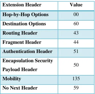
IPv6 allows packets to send extra information through extension headers. The IPv4 options field was used to provide this capability, but IPv6 extension headers have more flexibility for both the length of the option information and for introducing new options in the future [1]. The extension headers are included as a part of the IPv6 packet payload instead of being in the IPv6 header and are indicated by the Next Header field in the IPv6 header. Current extension headers are defined for routing options, destination specific options, Internet Protocol Security (IPSec) headers, and mobility. Routing options extension headers are used to provide source routing which allows the originator of the packet determine the route through the network. Destination specific headers, called Destination Options, allow the sender of a packet to include specific information for the destination only. The Destination Options header is contrasted with the Hop-by-Hop extension header which contains information that must be examined at each hop the packet takes [1]. IPSec, an end to end security scheme, has two headers which can be used: the Authentication Header (AH) and the Encapsulation Security Payload (ESP) Header. Each header when used can provide authentication and integrity to the packets and the ESP Header provides encryption [56]. The mobility header is used to support Mobile IPv6, a protocol that allows devices to be
reachable by a single address wherever they are in the Internet [51]. The extension headers and the corresponding value used in the Next Header field are displayed in Table 2.1.
10
Extension Header Value
Hop-by-Hop Options 00
Destination Options 60
Routing Header 43
Fragment Header 44
Authentication Header 51
Encapsulation Security
Payload Header 50
Mobility 135
No Next Header 59
Table 2.1 Extension Header Values
While each extension has its own defined header format with different fields, all contain a Next Header field and a Length field. The Next Header field in the extension header can be another extension or the transport layer protocol.
2.1.4 ICMPv6
ICMPv6 is a protocol that is used to transfer informational and error messages between two nodes and is essential for IPv6 communication [49]. These messages are generally used to determine the reachability of a node and if there are errors in the packet length or formation. They also are used as a part of NDP to set up routes and give addressing information to end host.
ICMPv6 is an update of ICMP, the IPv4 version of the protocol [49] [50]. The header for both protocols is the same: four fields that contain the message type, message code, checksum and the body of the message. The message type indicates what type of information, whether
informational or error, is being sent. Examples of informational messages are echo requests and replies, commonly known as pings. An example of an error message is a parameter problem type
11
which might indicate a difficulty like an invalid Next Header within the IPv6 header of a
received packet. The code field is used to provide further granularity for a message. For instance, a parameter problem message can be caused by several different errors such as an unrecognized next header value, an unrecognized IPv6 option, or an unexpected header field and the code field can be used to narrow which error caused the message. ICMP uses the code field in the same manner. The third field is the checksum field which verifies that the message was not corrupted in transit. ICMPv6’s calculation of the checksum differs from ICMP by including a “’pseudo-header’ of IPv6 header field” along with the ICMPv6 message [49]. The fourth field contains the body of the message being sent and is the same in both ICMPv6 and ICMP.
ICMPv6 uses a different set of values for message type. For instance, ICMP uses the values 0 and 8 for echo replies and requests while ICMPv6 uses the 129 and 128, respectively. ICMPv6’s message type values are separated into numerical ranges by error and informational types which does not occur with ICMP. Error message values are in the 0-127 and informational messages are in the 128-255 range. A complete list of the available ICMPv6 types provided by the IANA is in Table 2.2 [57]. Another value difference is the Next Header specification in the IP header. ICMP’s protocol value is 1 while ICMPv6’s is 58.
Type Name
0 Reserved
1 Destination Unreachable
2 Packet Too Big
3 Time Exceeded
4 Parameter Problem
100 Private experimentation
101 Private experimentation
102-126 Unassigned
127 Reserved for expansion of ICMPv6 error messages
128 Echo Request
129 Echo Reply
130 Multicast Listener Query
131 Multicast Listener Report
12
133 Router Solicitation
134 Router Advertisement
135 Neighbor Solicitation
136 Neighbor Advertisement
137 Redirect Message
138 Router Renumbering
139 ICMP Node Information Query
140 ICMP Node Information Response
141 Inverse Neighbor Discovery Solicitation Message
142 Inverse Neighbor Discovery Advertisement Message
143 Version 2 Multicast Listener Report
144 Home Agent Address Discovery Request Message
145 Home Agent Address Discovery Reply Message
146 Mobile Prefix Solicitation
147 Mobile Prefix Advertisement
148 Certification Path Solicitation Message
149 Certification Path Advertisement Message
150 ICMP messages utilized by experimental mobility protocols
151 Multicast Router Advertisement
152 Multicast Router Solicitation
153 Multicast Router Termination
154 FMIPv6 Messages
155 RPL Control Message
156 ILNPv6 Locator Update Message
157-199 Unassigned
200 Private experimentation
201 Private experimentation
255 Reserved for expansion of ICMPv6 informational messages
Table 2.2 ICMPv6 Message Types from IANA
ICMPv6 messages are also used by NDP to help facilitate routing. The next section will discuss NDP and routing in more detail.
13
2.1.5 NDP
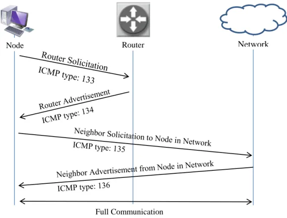
NDP is the protocol used by IPv6 to help nodes discover each other on a network, establish routes and receive subnet information from the network [2]. It provides the functionality of the Address Resolution Protocol (ARP) which is used by IPv4 to find nodes on a network and accomplishes this through the use of a set of ICMPv6 messages. The specific ICMPv6 message types used for NDP are 133-137 and are the Router Solicitation, Router Advertisement,
Neighbor Solicitation, Neighbor Advertisement, and Redirect messages.
As a part of IPv6 addressing, NDP is used to provide subnet information from the network while establishing the route for the node in the network. The sequence for this process is as follows: A request for the subnet information is sent to the router using router solicitation messages when a node joins a network. The router will respond with an advertisement message which contains the subnet prefix information. The node will then complete its 128-bit IPv6 address and will be reachable by the network. A node will send a neighbor solicitation message for the destination node when it wants to communicate. The receiving node will reply with a neighbor
advertisement message indicating it is reachable. The intended communication will then follow. The interaction between a node joining the network and router using NDP is illustrated in Figure 2.6.
14
Figure 2.6 NDP Interaction
NDP improves upon IPv4’s route establishment because the protocol contains all the messages needed for this process whereas IPv4 has to use a combination of ARP and ICMP to accomplish network discovery. ARP is used to resolve IP addresses to their corresponding MAC addresses and ICMP is then used to discover routers. NDP also enables auto-addressing as previous discussed. More ways that ICMPv6 improves upon IPv4’s mechanisms can be found in its RFC [2].
2.2 Voice over IP
Voice over IP (VoIP) refers to voice and media communication services provided over the Internet protocol. There is no formal definition for VoIP by the U.S. Federal Communications Commission [31]. VoIP is used to support telephone calls over the internet versus the traditional
Networ
Network
Router Node
15
analog telephone network. Companies such as Skype and magicJack provide VoIP services to home users and have seen growth in usage [5] [6]. In 2011, Skype usage grew 48% and the service accounted for twice the amount of international calls than traditional phone companies [32]. This shows that VoIP is a common application among household users.
VoIP services can be accomplished using a variety of different protocols over IP. Some protocols are open such as Real-time Transport Protocol (RTP). Other protocols are proprietary such as the Skype protocol which is based on peer-to-peer concepts [5]. Home users and companies should compare the options available when considering which standard to use. One way to compare the protocols is to consider the quality of service. VoIP’s objective quality of service can be
measured with a set of metrics including latency, packet loss and jitter. The Mean Opinion Score (MOS) and the R-Factor are specific metrics for VoIP that involve subjective ratings [7]’
therefore, a combination of metrics should be used to obtain a complete measurement of VoIP’s quality of service for the comparison between protocols.
The components of VoIP are the codecs, the signaling process, and media servers, gateways, and clients. Each of these plays a part in the successful establishment of a VoIP application. A codec is an encoding/decoding program that coverts analog audio into digital and vice versa. VoIP applications have a plethora of codecs to choose from to use, all with varying compressions and quality. Designers of VoIP applications choose codecs based on their determined requirements for quality and latency; therefore, each application is different. Media servers process data streams and handle connections between clients. Media gateways are devices that connect different types of networks together, like an IP network with a Public Switched Telephone Network (PSTN), so that clients on disparate networks can communication. Media clients are the nodes that are actually generating and receiving calls.
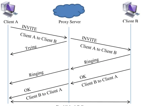
The signaling process establishes the setup and tear down required for each VoIP session. One of the standard signaling processes is the Session Initiation Protocol (SIP) [58]. SIP is an
application layer protocol that uses a peer to peer connection for initiating a session. The components needed for SIP are the proxy server which listens for calls and facilitates the connection and clients which initiates the calls. Clients need to use identities specific to SIP to
16
call each other; these identities are analogous to telephone numbers or email addresses and are bound to an IP address. SIP uses a similar request and response format to HTTP [58]. Initiation of a call starts with an “INVITE” message, containing source and destination addresses and the type of session, which is routed to the destination through the proxy servers. The servers must report back to the client that they has received the “INVITE” message and are finding the route to the destination by sending a “Trying” message. Once the “INVITE” message is received by the destination client, two messages can be sent: a “Ringing” message and an “OK” message. A “Ringing” message is always sent back to the call originator indicating that the client has been reached but has not answered the call request. An “OK” message is sent when the destination client has answered the call request; this completes establishing the connection. Apart from the “INVITE,” “Trying,” “Ringing,” and “OK” messages, SIP has several other messages that are used to indicate a variety of responses, including errors; the full list can be found in the RFC [58]. The SIP session establishment is displayed in Figure 2.7.
Figure 2.7 SIP Establishment Process
Client B
Proxy Server Client A
17
2.3 Moving Target IPv6 Defense
Research completed in the Virginia Tech Information Technology Security Lab (ITSL) revealed that there are several privacy issues pertaining to IPv6 addressing. One particular privacy issue found with SLAAC addressing is that network users can be tracked across subnets by potentially malicious people scanning for their Modified EUI-64 values. In response to these issues and vulnerabilities, a specialized application called a Moving Target IPv6 Defense (MT6D) was created by Dunlop [8]. MT6D was tested on Virginia Tech’s IPv6 production network by Dunlop and in simulation as a part of this work.
MT6D is a scheme in which the vast IPv6 address space is taken advantage of by having users constantly rotate addresses, preventing an attacker from being able to find and correlate packets between two users. Users of MT6D keep track of their correspondent by calculating each other’s next address rotation. Addresses are calculated with a shared key, the EUI-64 and a timestamp. The shared key and MAC address of the users must be exchanged before enabling MT6D. The exchange of this information is left to the discretion of the users. It is also essential that the two users have synchronized clocks to maintain the same timestamp. MT6D accomplishes clock synchronization by periodically querying a common time server between the devices.
To use MT6D, the application can be installed directly onto a physical machine or onto a separate device that sits between the machine and the network. MT6D was tested in simulation using a physical machine that had the application directly installed on it. Once installed, MT6D has four configuration files. Three configuration files maintain mappings of MAC addresses to human readable device names, human readable device names to IP addresses, and human
readable device names to shared keys. The fourth configuration file maintains all MT6D options including address rotation time (adjustable to seconds), AES encryption, and dynamic subnet obscuration. The MT6D options configuration file must be the same between two users otherwise communication will fail. After configuring these files, MT6D can be enabled.
MT6D’s execution process starts by making a virtualized network interface. This interface maintains the device’s original IP address and generates all outgoing traffic. All packets from the
18
virtualized interface are captured by the MT6D application and wrapped in the MT6D header. The MT6D header is an IPv6 header that uses the rotating addresses as the source and
destination. If encryption is enabled, a Destination Options extension header is generated
containing information about the encryption type. Furthermore, MT6D uses UDP as the transport layer protocol and the original packet is contained in the UDP header’s payload. When a MT6D packet is received, the application strips the MT6D header off the packet, decrypts the original packet if necessary and forwards it to the virtualized network interface. The machine then responds to the packet normally.
Overall the MT6D application provides anonymity to users and can provide encryption for data. This scheme adds an extra layer of security to user’s existing security infrastructure contributing to the defense-in-depth concept. More information on MT6D can be found in Dunlop’s work [8]. .
2.4 Chapter Conclusion
An understanding of IPv6, VoIP, and MT6D is vital to comprehend the focus of testing in this thesis. The chapter described key attributes of IPv6 particularly addressing, extension headers, and network discovery. VoIP’s main components were explained with a focus on establishing a session using SIP. The MT6D application process of providing privacy to users was expounded upon, including the configuration options.
19
3. OPNET Modeler and the System-in-the-Loop Module
OPNET is a company that provides software solutions targeted at network management [3]. Modeler is their network simulator which is used in network research and development. Other products focusing on network monitoring, auditing and planning are available for purchase. This chapter describes OPNET Modeler and the System-in-the-Loop Module.3.1 OPNET Modeler Overview
OPNET Modeler is a discrete event simulator that allows users to build and test network
configurations and protocols. It is used by a variety of companies such as the Harris Corporation, Intel and Ericsson as well as the U.S. military [33]. The simulator is advertised to support a broad range of protocols and statistics gathering methods. It also provides a large set of simulated network devices and links, such as routers and switches, including devices from proprietary sources (Cisco, Juniper, etc.).
Modeler uses a graphical user interface to drag and drop a pre-defined library of nodes into a network topology. The user can then define attributes for each node using menu options. Each simulated node can be broken down into a set of connected processes which in turn consist of state diagrams. The states of each diagram are created using C/C++ code that use the OPNET coding libraries. This design allows for the user to have control over the node at all levels of abstraction as well as being able to define specialized nodes. Each level of abstraction for a node within the Modeler interface is shown in Figure 3.1. The top left corner displays a node in the main interface. The bottom left corner shows the next level of abstraction which is the process diagram of the node. The top right corner is the state diagram for a single process and the bottom right corner displays the code used to create the states. Each level can be modified by the user resulting in a custom model by adding or changing processes, states, and code. Link models are customizable as well if a user desires a different set of parameters for a link.
20
21
Modeler has a wide set of statistics available including capturing the amount of packets of a specific protocol or application received and sent by an interface, latency, link load, etc.
Statistics can be displayed as is, as an average, or by a defined distribution. The user can specify whether to capture statistics on a specific node or on the network as a whole. Statistics, like node models, are customizable by the user by modifying the capture rate and method.
Modeler’s features are extended through add-on modules, like IPv6 and wireless support, available from OPNET [1]. The System-in-the-Loop module (SITL) provides the capability to translate real network data into simulation [4]. This allows premade hardware prototypes and software to interact with a simulated network without having to create a simulation model of these prototypes. SITL is advertised to support a set of basic protocols which includes IPv6. This module is described in the following section.
3.2 The System-in-the-Loop Module
SITL is an add-on module to OPNET Modeler that allows real traffic to be sent to and from the simulation environment. This is a great benefit for applications and tools that are in hardware or are in the prototype stage. It can also be used when applications are complex and cannot be simplified into a simulated node.
SITL operates by working as a translator between the live network and the simulated network. The translation module is configured to pull and send packets with a specific network interface. A packet filter must be written to specify which packets should be translated into simulation from the live traffic. SITL uses the Berkeley Packet Format as the syntax for these packet filters. It is suggested by OPNET that one network interface per SITL process be used to make the filtering process easier to handle; however, it is not required. One network interface can be used for several SITL processes within the simulated network topology provided that a proper packet filter is written for each process. For this research, OPNET’s suggestion was taken into
22
simplify the simulation process and reduce the configuration time. Two D-Link USB 2.0 Ethernet adapters were purchased to be used solely for the simulations.
SITL has three configurations to set up communication between live software or hardware and the simulated network. The configurations are named Live-Sim, Sim-Live-Sim and Live-Sim-Live and are illustrated in Figure 3.2. The names are an explanation of the networks through which the packets travel. Live-Sim is the configuration in which packets are sent from a live network and have a final destination to a simulated node. Sim-Live-Sim is the configuration in which packets are generated in simulation, sent through a live network and have a final
destination back in simulation. An example of this is to have two simulated workstations that are connected through a live switch. Live-Sim-Live is the configuration in which packets are
generated in a physical environment, sent through a simulated network and have a final destination of a real network/device. Live-Sim and Live-Sim-Live are the two main configurations used in this work.
Figure 3.2 The Three Configurations of SITL
Simulation
Simulation
Simulation Simulation
a) Live-Sim Configuration
b) Sim-Live-Sim Configuration
23
The primary process in the SITL node is the translation function. The translation function is a set of three methods that change real packets into simulated ones and vice versa. The three methods are a testing method, a translation method from simulation to real, and a translation method from real to simulation. The testing method looks for characteristics in incoming and outgoing packets that determine what type of protocol is being used. It will return true or false depending on if the translation function is able to translate the detected protocol. For example, a translation function exists for TCP. The testing method looks for the protocol number within the IP packet header. If it detects the correct number, the method returns true and the TCP translation function is used. Testing methods are defined with a priority number and are executed in order by the SITL process. The first testing method to return true executes its corresponding translation function. Incoming and outgoing translation functions (in relation to the simulation) step through each bit of the header, using that information to create a packet, either into simulated packet form or as a real packet stream.
OPNET has pre-defined translation functions for Ethernet, IPv4, IPv6, ICMPv4, ICMPv6, ARP, TCP, UDP, OSPF, RIPv2 and WLAN [34]. Users can create their own translation function for other protocols as well. The customized functions must define three methods — testing, real to simulation, and simulation to real — and a method that registers the function along with its testing priority with the SITL process. One condition on this customization is that the protocol being translated must have a defined simulated packet form in Modeler. If one does not exist, then the user must first define the packet format. This can be done within the Modeler GUI.
3.3 The Advantages and Disadvantages of OPNET Modeler
There are advantages and disadvantages with using OPNET Modeler. The clear disadvantage is that OPNET is a proprietary simulator and costs money to use. A license must be purchased to run the Modeler software and each add-on module (IPv6, SITL) requires an additional license. OPNET has an educational program that gives out free licenses for some of their products to universities that qualify [35]. Paying for Modeler provides access to technical support and user forums which are otherwise not available to the general public. The forums are not particularly
24
active; new posts occur every 1-2 weeks averaging 0-5 replies [36]. The lack of activity on the forums can be seen as a further disadvantage.
There are many advantages to using OPNET despite the cost. The first advantage is that proprietary network models from companies like Cisco are available for building network topologies. Other network simulators do not have these models available by default; users of other simulators have to create their own network models. The availability of these proprietary models helps users to create network topologies that closely match existing networks. For
example, a system administrator could build a simulation using Cisco devices that exist in his/her live network. A second advantage is that the OPNET software is generally reliable. Open source projects can contain software bugs that may not be fixed in a timely manner. Since OPNET is proprietary, customers expect that patches will be made quickly to fix any known error. A third advantage is that Modeler does advertise to support a great amount of protocols. For example, in comparison to ns-3, Modeler has more routing protocols implemented [34] [37]. A fourth
advantage is that OPNET provides training classes for their products for new users. This helps decrease the time to learn the details of the software and decrease the time to create effective simulations. Finally, a fifth advantage is that OPNET conducts its own conference that showcases new features and updates to products, customer research and development, and further educational outreach.
3.4 The Use of Modeler in this Research
OPNET Modeler and SITL were used to create a series of network topologies as a framework to assess IPv6 applications. A full evaluation of the software for IPv6 support was done through a set of tests. Chapters 5 and 6 will describe the network configurations, tests and results of this evaluation. The developed framework described in Chapter 5 was used to test a VoIP application and MT6D. The IPv6 application test methodology and results can be found in Chapter 7.
25
This chapter described OPNET Modeler and the SITL module. The main interface and components of simulation were covered and the configurations of SITL were detailed with examples of how they are used. The advantages and disadvantages of using Modeler were discussed with the advantages outweighing the main disadvantage of cost.
26
4. Simulation Tools and Related Research
Simulation tools are readily available for network and application testing and are used abundantly in academic research. Several major concepts from previous work on simulation frameworks, including the choice of simulation tool, were used as building blocks in creating the IPv6 simulation framework. Since OPNET Modeler was chosen as the simulator for the
framework, a literature review of work done using Modeler and the SITL module in IPv6 was done. Section 4.1 gives the overview of simulation tools examined for the framework and Section 4.2 presents the literature review on simulation frameworks and OPNET.
4.1 Simulation and Emulation Tools
There are several tools available to create network simulations. Four tools researched before deciding to use OPNET Modeler as the tool to create the IPv6 framework. Tools were looked at with two criteria. First, it had to support IPv6. Secondly, it had to have the ability to tie in live network traffic. This second criterion was based on the fact that MT6D had an existing
developed prototype. Any additional features counted positively towards the tool. Four simulation/emulation tools were considered based on the criteria: ns-3, OMNeT++, Common Open Research Emulator (CORE) and OPNET [18][19][20][3].
ns-3 is a discrete event simulator that is used widely in educational research. It is primarily used to simulate IP/wireless networks [18]. C++ or Python code is accepted to describe models to develop a simulation. The command line and code is the main avenue for running and building a simulation. It does not visualize any of the networks and does not have an integrated debugger. ns-3 does have a system in the loop capability that works as a scheduler between real network traffic and virtualized traffic which met one of the criteria. ns-3 version 3.10 was the stable release at the time of evaluating simulators for this work (January 2011). This version of ns-3 has several IPv6 classes, but lacks support in some areas. For instance, it does not support global routing for IPv6. Global routing was added by the developers to a later release during the
27
summer of 2011 [38]. Another lacking area of the 3.10 release is that TCP and UDP are not supported with IPv6. Support for these transport layer protocols has been added in the 3.14 release of June 2012 [39]. Since ns-3 was found to lack in some areas of IPv6 support, it was not chosen for this framework.
OMNeT++ is a C++ based simulation library and framework to help build network simulators [19]. It is an open source project that is maintained and contributed to by the academic
community. There are several pre-built tools; one such tool is the xMIPv6 project which supports Mobile IPv6. The project has subsequently been moved into the main INET framework. The framework documentation describes IPv6 and ICMPv6 support, but does not provide the same detail as ns-3’s documentation [40]. OMNeT++ did not have a mechanism for live network communication at the time of comparison, therefore, OMNeT++ was not chosen as the simulation tool as it did not meet the second criterion. A secondary project, TTE4INET: the Time Triggered Ethernet Model for the INET Framework, was developed and released in February 2012 [21]. This project allows for real time communication with simulation which helps OMNeT++ meet the criteria; however, it was released after a majority of this research had been done.
CORE is an emulation project that was developed by the Boeing Corporation for the United States Navy [20]. The benefit of this tool is that the emulations can be run on multiple machines and can be connected to live networks. The network devices are emulated which makes it easy to customize devices to run and support various protocols including IPv6 and custom applications such as MT6D. One of the drawbacks of emulation is that these devices have to be individually configured as virtual machines (VMs). A machine needs to have sufficient resources to handle the additional RAM and hard disk space needed for VMs. For example, if there are 10 VMs with 1GB of RAM to be emulated, the emulation machine needs to have at least 10GB of RAM free. The additional time and resources needed to configure and host the emulations was not available; therefore, CORE was not chosen as the emulation tool.
The last tool evaluated was OPNET Modeler [3]. As discussed in the previous chapter, OPNET fits the two criteria of supporting real time traffic communication with simulation through SITL
28
and advertised IPv6 support. The advantages of providing proprietary network models, training classes and meeting the two criteria made OPNET the choice for this framework.
4.2 Related Research on Simulation Frameworks
Simulating a network environment is not a new concept. Many researchers have looked to simulation as a viable way to test new network configurations and new network device models. There are several examples of simulation frameworks developed for live networks, new
protocols and wireless configurations. The following frameworks helped develop this research by verifying areas that have been already tested and by revealing topics that have not been examined.
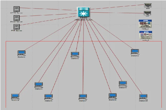
Two studies were found that created campus network frameworks using OPNET Modeler. One study was run by SUNY Fredonia [9] and the other was done by K.U. Leuven in Belgium [10]. The purpose of the SUNY Fredonia framework was to study the performance of the new Gigabit Ethernet backbone and of voice traffic over the network. They built their framework with a combination of Cisco and custom models and ran six scenarios. The study from K.U. Leuven created a simulation model of their campus network which included a five switch ring as its core topology. As with the SUNY Fredonia campus framework, voice traffic was used as a case study. Through these two studies, it was determined that voice traffic is a standard application to simulate over networks when looking at performance.
Various test bed studies and publications on IPv6 have been produced. One particular piece of literature gave an overview of IPv6 test beds in China circa 2004 [11]. China has several live research networks run by educational institutions and the government, four of which were described in this paper as being a part of countrywide IPv6 study. Another study was found on an IPv6 wireless sensor network in China [12]. The sensor network test bed was likewise a live network and it contained a series of 20 sensor nodes, a sink (gateway device), and an IPv6 server/database. The results of Huo et al. represented the hardware limitations of developing a physical test bed versus one in simulation. A third publication was found that expounded upon
29
work on test beds in France which were used for a number of projects including testing IPv6 mobility, voice traffic and web browsing [13]. These test beds give an interesting perspective on live network testing versus pure simulation. The study from Montavont et al. contributed to the use of VoIP as a standard testing application for IPv6 networks for the framework.
Certain aspects of IPv6 in OPNET Modeler have been researched. An evaluation of IPv6 Simulation in OPNET was done in 2003 by Chang et al. which looked at the internal simulation IPv6 model [14]. It focused on the IPv6 ping model, IPv6 tunnels and routing protocols in
particular. The example networks in this paper are very similar to the OPNET IPv6 tutorial and it was reasoned that this evaluation helped create the OPNET tutorial. The study did not adequately cover IPv6 traffic generation in simulation and so it was determined that the model should be re-evaluated. Another evaluation was found concerning Mobile IPv6 in OPNET [15]. It examined the Mobile IPv6 model’s configuration and then did several tests with application traffic. They found that the implementation of the handover procedure of Mobile IPv6 had adverse effects to the congestion control of the transport layer which helped to indicate that there could be some other unseen problems within the OPNET IPv6 implementation. The most recent study examining IPv6 in OPNET was published in December 2011 and examined voice traffic performance in dual stack networks [16]. A topology was developed and used to study voice traffic in both IPv4 and IPv6. The study was done completely in simulation and used OPNET’s ability to create a custom application to set the voice traffic.
A study that created a Virtual/Live Gateway process for IPv6 using OPNET provided
information on the process of characterizing applications [17]. The purpose of the Virtual/Live Gateway was to serve as a communication mechanism between simulation and external data. It was concluded by the authors that the Virtual/Live Gateway process was suited for single packet, non-real time traffic. The authors suggested further research into developing the gateway to handle a wider range of application traffic and simulation environments. They also proposed further work into having the gateway generate real packets. No further publications on the proposed further work could be found.
30
4.3 Chapter Conclusion
This chapter described three simulation tools and one emulation tool that were considered for this work. It described the criteria used for consideration and how each tool met or did not meet the criteria. It also covered related research of simulation frameworks. The results of the
literature review revealed that OPNET was the best suited simulator for this research but had not undergone a full IPv6 traffic evaluation and VoIP is generally used as a standard application in test beds.
31
5. Configuration and Network Topology Design
The choice of the configuration and topology for a simulation is dependent on the statistics being measured and the desired nodes in the network. The simulation measuring the effects of traffic on a router would be configured and designed differently than the simulation monitoring the effects of mobility on a router. In two major section of this chapter, the configuration options and topology choices made to make the IPv6 application simulation framework are explained. The first section describes the configuration between the simulator and the live application machines. The second major section describes the network topology for each scenario in the framework.
5.1 Live Network Configuration
There are two ways to set up the live network to interact with the simulated environment. The first way is through the use of Virtual Machines (VMs). These VMs can be hosted on the same machine as the simulation software or separately on a remote server. The second way is to use real machines that physically connect to the simulation network. This section describes the set up for each configuration and discusses their benefits and limitations.
5.1.1 Virtual Machine Configuration
VMs are a good alternative to use when there are limited physical machines available because they virtualize the components of a real machine, like the processor, buses, and peripherals, and a full operating system. Software testers are attracted to using VMs since they can easily test software on a variety of systems without having to configure and run a full physical machine. There are two main companies that provide free virtualization: VMWare and VirtualBox [41] [42]. VMWare is a leading virtualization company that provides services across all levels, from the home user to large businesses. . VMWare Player is their free virtualization solution for home users. VirtualBox is an open source virtualization solution from Oracle that provides the same
32
services as VMWare player. It has more flexibility and configuration options than VMWare Player. VMWare has solutions that have the same flexibility and configuration control, but these solutions are not free.
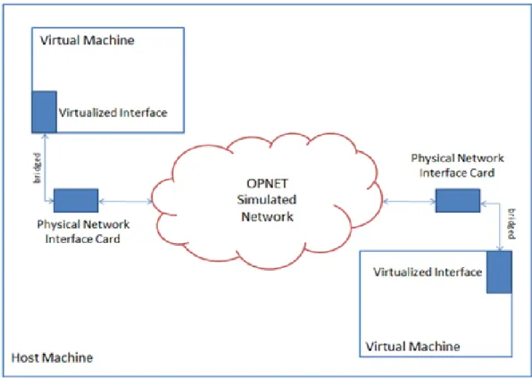
VMs were used to do the IPv6 evaluation of OPNET Modeler and SITL. VMWare Player was chosen as the virtualization agent as it provided the most stable network configuration through initial trials. The VirtualBox solution was tried, but full communication with the machines and simulation was never achieved. The network bridging mechanism of VirtualBox was determined as the problem area as other means of networking (Network Address Translation and a host-only network) worked correctly.
There were three VMs made to be used for the IPv6 OPNET evaluation. Two VMs used the Ubuntu 11.10 operating system (OS) which supports IPv6 and can be easily configured to run a webserver. Wireshark [23], a packet capturing tool, was loaded onto these machines to help monitor packets across the network. The third machine ran Backtrack 5, a penetration testing Linux distribution [43]. Backtrack 5 contains several packet crafting tools that were used for the IPv6 extension header tests. Each VM has its virtualized network interface bridged with one of the USB NICs. The configuration between VMs and the simulation on the host machine is shown in Figure 5.1.
33
Figure 5.1 Configuration of VMs on a Host Machine
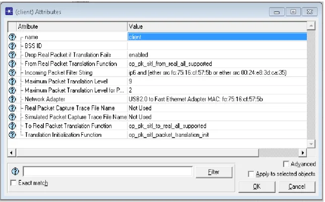
The SITL process was configured with the NIC bridged with the VM and packet filter. The packet filter followed the same syntax for each SITL node:
ip6 and (ether src <Virtualized NIC MAC address> or ether src <USB NIC MAC address>).
There are three main parts to this filter the first of which is “ip6.” This part is intuitive; the filter allows IPv6 packets through to simulation while dropping IPv4 packets. The second part is “ether src <Virtualized NIC MAC address>” which filters for packets containing the Virtualized NIC Ethernet address as the source address. The third part is ether src <USB NIC MAC
address>.” It only allows packets with the USB NIC Ethernet address as the source address though to simulation. These three parts completely form the filter that allows for the correct packets to be translated into simulation and any unrelated packets to be dropped. The SITL NIC and packet filter set in the attributes menu is shown in Figure 5.2.
34
Figure 5.2 SITL Attributes Menu
There are two main benefits to using VMs to host an application and generate packets. The first benefit is that extra machines are not need. The entire set of components for simulation can be contained on one physical machine providing that the host machine has free space for the VM files which allows more control over the system settings, particularly network interface
configuration. The second benefit is that configuring of a new VM is fast and simple. VMs are easily duplicated so only one full configuration of a VM is needed if all the VMs have the same parameters. If the OS is a variable in the simulation, then new VMs with different OSs can be configured quickly without having to worry about compatibility with physical hardware.
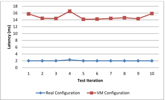
The VM configuration has limitations as well. The biggest limitation of using VMs is that the host machine must have enough memory resources to contain the memory it uses and the memory of the VMs. Since VMs take up space on a host machine, the simulation performance can be affected. One possibility is that the simulation has a smaller space to grow which affects the performance. Simulations with a large amount of events will take longer to execute and have the potential to abort the program entirely. Another effect is that there is a measureable delay
35
when transferring packets between the network interfaces. This extra time of passing packets between the virtualized network interface to the USB NIC adds to latency. The additional latency was made clear in a comparison ping flood test between using VMs and real machines. The VM configuration averaged 14.88ms for a 50,000 packet ping flood over 10 iterations. The real configuration averaged 2.04ms with the same test. The results of this comparison test are summarized in Figure 5.3. The observed additional latency was one of the determining factors for not choosing the VM configuration for the IPv6 application testing.
Figure 5.3 Comparison Ping Flood Test Results
5.1.2 Real Machine Configuration
The real machine configuration for hosting applications and generating traffic comes closer to mimicking a live environment. The network is the only item simulated in this configuration. This configuration was used for IPv6 application testing because it minimizes added effects from the configuration. The configuration is similar to the VM configuration with some slight differences, notably the connection between the devices and the simulated network.
0 2 4 6 8 10 12 14 16 18
1 2 3 4 5 6 7 8 9 10
Late n cy ( m s) Test Iteration