IGNIS 1000
CONVENTIONAL FIRE DETECTION AND ALARM SYSTEM
IGNIS 1240
FIRE DETECTION AND ALARM
CONTROL PANEL
Operation and Maintenance Documentation
ID-E299-001E
The IGNIS 1240 conventional fire detection and alarm control panel covered by the present manual complies with the requirements of the following European Union Directives:
CPD 89/106/EWG on construction materials;
EMC 2004/108/WE on electromagnetic compatibility
LVD 2006/95/WE on low-voltage electric equipment.
The IGNIS 1240 control panel has been approved with the EC-Certificate of Conformity No. 1438/CPD/0152 issued by the Scientific and Research Centre for Fire Protection (CNBOP) Józefów, Poland, an EU notified authority No. 1438, confirming its compliance with the requirements of PN-EN 54-2:2002+A1:2007 standard. The certificate may be downloaded from www.polon-alfa.pl web site. The device has been also approved with the Allowance Certificate No. 0508/2009 issued by CNBOP.
1438
Polon-Alfa Spółka z ograniczoną odpowiedzialnością Sp. k. 155, Glinki Street, PL 85-861 Bydgoszcz, POLAND
09 1438/CPD/0152 EN 54-2:1997+A1:2006
IGNIS 1240 fire detection and alarm control panel
Conventional, for indoor use Provided options:
- fire alarm devices output - output signal delays
- interdependent alarming (A type dependence) - testing mode
- alarm counter
and additional functions, inputs and outputs: see technical data contained in ID-E299-001 manual
Read the manual carefully before the detector assembling and commissioning.
Any nonconformity with the instructions contained in the manual may be harmful or may cause violation of the law in force
POLON-ALFA bears no responsibility for any damage resulting from usage inconsistent with the manual.
A waste product, unsuitable for further use, shall be passed to a waste electric and electronic equipment collection point.
NOTE: The manufacturer reserves the right to change specifications of products at any time without prior notice.
CONTENTS
1 INTRODUCTION ... 5
1.1 DOCUMENTATIONCONTENTS ... 5
1.2 CONTROLPANELAPPLICATION ... 5
1.3 SAFETYCONDITIONS ... 5
1.3.1 Electric shock protection ... 5
1.3.2 Installation and equipment safety ... 5
1.3.3 Repairs and maintenance ... 5
1.3.4 Fuse replacement ... 6
1.4 DEFINITIONS ... 6
1.5 DEVICECOMPLETENESS ... 6
2 TECHNICAL SPECIFICATIONS... 7
3 GENERAL OPERATION PRINCIPLE ... 8
4 CONTROL PANEL DESIGN ... 9
4.1 OVERALLCONTROLPANELDESCRIPTION ... 9
4.2 HANDLINGANDSIGNALLINGELEMENTS,ACCESSLEVELS ... 9
4.2.1 Handling elements and indicators on front panel ... 9
4.2.2 Handling elements inside the control panel ... 11
5 CONTROL PANEL FUNCTIONALITY ... 12
5.1 LCDINDICATIONSAT1STAND2NDACCESSLEVELSERVICING ... 12
5.2 CONTROLPANELFUNCTIONSAT2NDACCESSLEVEL ... 13
5.2.1 Current date and time setting ... 14
5.2.2 Zone (detection line) testing mode disablement/re-enablement ... 14
5.2.3 Zone disablement/re-enablement ... 14
5.2.4 Faults readout ... 15
5.2.5 Disablement/re-enablement of all zones simultaneously ... 16
5.2.6 Alarm counter readout ... 16
5.3 CONTROLPANELFUNCTIONSAT3RDACCESSLEVEL ... 17
5.3.1 Alarming lines (signalling devices) operation option setting... 17
5.3.2 General alarm relays actuation delay programming ... 17
5.3.3 General alarm signal transmission delay disablement/re-enablement ... 18
5.3.4 Event memory reset ... 18
5.3.5 ‘Standard configuration’ loading ... 18
5.3.6 Alarm variants programming ... 19
5.3.7 Zone relay programming ... 22
5.4. QUIESCENT(SUPERVISION)MODE ... 22
5.5. ALARMMODE ... 23
5.5.1 Fire alarm signalling ... 23
5.5.2 Fire alarm verification by the attending personnel ... 23
5.5.3 Automatic alarm signal verification, alarming variants... 23
5.6. FAULTMODE ... 25
5.7 DISABLEMENTMODE ... 25
5.8 TESTINGMODE ... 25
5.9 SIGNALTRANSMISSION/AUXILIARYEQUIPMENTCONTROLLING ... 26
5.10 ACOUSTICSIGNALLINGDEVICES ... 26
5.12 CONTROLPANELSPARALLELOPERATION ... 27
6 POWER SUPPLY ... 27
6.1. BASICPOWERSUPPLY... 27
6.2. RESERVEPOWERSUPPLY ... 27
7 INSTALLATION ... 28
7.1 CONTROLPANELMOUNTING ... 28
7.2 WIRING ... 28
8 COMMISSIONING AND CONFIGURATION ... 29
8.1 COMMISSIONING ... 29
8.2 STANDARDCONFIGURATIONLOADING ... 29
9 SOFTWARE FOR EVENT MEMORY READOUT ... 30
9.1 EVENTMEMORYGENERALDESCRIPTION ... 30
9.2. HARDWAREREQUIREMENTS ... 30
9.3 CONTROLPANEL-COMPUTERCONNECTION ... 31
9.4 SOFTWARELAUNCHINGANDEVENTMEMORYREADOUT... 31
10 CONTROL PANEL SPECIAL APPLICATIONS... 32
10.1 EXPLOSIONENDANGEREDPREMISESPROTECTION ... 32
11 INPUT AND OUTPUT CIRCUIT CONNECTING TERMINALS ... 33
12 MAINTENANCE ... 36
12.1 GENERALRULES ... 36
12.2 PERIODICALTESTING ... 37
12.3 FUSEREPLACEMENT ... 37
1
INTRODUCTION
1.1 DOCUMENTATION CONTENTS
The purpose of this Operation and Maintenance Documentation (OMD) is to present the application, design and operation of the IGNIS 1240 fire detection and alarm control panel which constitute a part of the fire detection and alarm system. The documentation contains necessary information on the IGNIS 1240 control panels for designers, fitters and maintenance technicians. Together with the User Manual IO-E339-001, intended for those who are on duty directly at the control panel, it makes the complete operating documentation attached to the control panel and delivered to its user.
1.2 CONTROL PANEL APPLICATION
The IGNIS 1240 fire control panel is designed to:
1. signal a fire occurrence detected by an interoperating fire warning devices (automatic and manual),
2. indicate a fire endangered place by identification of the alarming detector line, 3. actuate fire protection equipment,
4. transmit a fire information to monitoring systems.
The control panel interoperates with the 30 and 40 model range two-state (conventional) detectors manufactured by Polon-Alfa. It is intended for installation in medium-sized objects, e.g. offices, commercial and industrial buildings, etc. it is adapted for continuous operation in premises of low dust level at temperature range from - 5 °C to + 40 °C and air relative humidity up to 80 % at +40 °C.
1.3 SAFETY CONDITIONS
1.3.1 Electric shock protection
The IGNIS 1240 fire control panels are ranked as the 1st protection class devices and can be used only in the case of application of additional protection against electric shocks, such as zeroing or protective grounding.
230 V/50 Hz mains supply circuits insulation is reinforced and resists 2800 V voltage test; low-voltage circuits (below 42 V) insulation is able to resist test voltage of 700 V DC.
After connecting the mains power supply conductors, the mains connection must be protected with a manufacturer's shield.
1.3.2 Installation and equipment safety
Wire installation should be made using conductors of the required fire resistance and should be properly protected in passages through fire zone boundaries. In order to avoid undesirable interaction, a required distance between the low-voltage installation and a power installation and a lightning protection system should be maintained. From the system electromagnetic interference immunity, it is recommended to utilise protective grounding. Reserve power supply batteries should be connected to the panel at the final stage of the installation.
The panel components are heat sensitive. The maximum ambient temperature should not exceed + 40 °C. The space left around the device should be big enough to secure free air flow. Air humidity in the premises where the panel operates should not exceed 95 %.
1.3.3 Repairs and maintenance
Maintenance works and periodic inspections should be executed by skilled personnel employed by companies authorised or trained by Polon-Alfa. Any repairs must be carried out by the manufacturer.
Polon-Alfa bears no responsibility for the operation of any apparatus being serviced or repaired by unauthorised personnel.
1.3.4 Fuse replacement
In the event of fuse replacement, an equivalent fuse replacement should be used: of the appropriate type and nominal value. The appropriate types and nominal values are contained in p. 12.3.
1.4 DEFINITIONS
Detection line - a two-core line with detectors installed in, terminated with an end-of-line resistor.
Fire warning device - a fire detector or manual call point.
Detection point – a fire warning device, installed in the supervised premises, installed in a detection line.
Detection zone - a separated area supervised by fire warning devices installed in one detection line.
Monitoring line - a two-core line that supervises the monitoring contacts of external fire devices.
Alarm line - a two-core monitored line that actuates external signalling devices or fire-fighting equipment.
Output to monitoring – a control panel relay output that enables transmission of fire and fault signals to a monitoring centre or to the Fire Brigades.
Quiescent (supervision) mode - an operation mode, in which the control panel is power supplied from an electric energy source that meets the settled requirements, during which no other operation mode is indicated.
Alarm (fire) mode - an operation mode the control panel triggers after receipt of a fire detection information from fire warning devices.
Disablement mode - an operation mode, in which it is deliberately blocked the control panel ability to receive signals from any fire warning devices and to evoke alarms, or the control panel output and/or transmission path to any fire detection and alarm system component that is a part of alarm circuit.
Testing mode - an operation mode in which the control panel indicates functions checking.
Fault mode - an operation mode in which the control panel indicates a fault of any circuit in the alarm installation or its own circuits.
1.5 DEVICE COMPLETENESS
Table 1 lists the items which compose the IGNIS 1240 control panel furnishings. Table 1
Item Description Quantity
1 2 3 4 5
IGNIS 1240 fire detection and alarm control panel Operation and Maintenance Documentation (OMD) Servicing manual
Warranty certificate Control panel unit package
1 1 1 1 1
Table 2 specifies the equipment for typical fire alarm systems, operating with the control panel in the IGNIS 1000 system, to be ordered separately in required quantities.
In the standard execution, the control panel is equipped with 16 detection lines. The ML-3 module (ordered separately) enables extension by further 8 detection lines.
Table 2.2
Item Description Remarks
1 2 3 4 5
12 V/17 Ah battery ML-3 module
Conventional fire detectors of 30 and 40 model range, including intrinsically safe execution Manual call points
WZ-31 additional indicator
two pcs required for control panel to extend panel capacity by 8 lines according to Appendix A
according to Appendix A
2
TECHNICAL SPECIFICATIONS
Overall dimensions L x H x G 392 x 482 x 190 mm
Mass (without batteries) < 11 kg
Ingress protection IP 30
Operation temperature range -5 °C ÷ +40 °C
Allowable operation relative humidity 95 % at +40 °C
Transportation temperature range -25 °C ÷ +55 °C
Power supply voltage:
50 Hz mains 230 V + 10 % - 15 %
reserve battery: internal or outside 2 x 12 V/17 Ah, e.g. KOBE HV17-12W
control panel of capacity ≤ 36 Ah
Battery charging current ≥ 1.7 A (without current consumption
by external devices) Current draw in quiescent mode:
- from mains < 800 mA
- from batteries (16/24 detection lines) < 170/228 mA Current draw in alarm mode:
- from mains < 800 mA
- from 17 Ah battery, max. < 600 mA
External devices power supply voltage 24 V + 25 % - 15 % Admissible current draw from external devices
power supply output, max. 800 mA
Number of detection lines:
- Standard 16
- with ML-3 module application 24
Detection line resistance, max. 2 x 120 Ω
Detection line insulation resistance, min. 100 kΩ Number of detectors installed in a detection line ≤ 32 Number of manual call points in a detection line ≤ 10 Number of all detectors and manual call points ≤ 512
End-of-line resistor in a detection line 5.6 kΩ, ±5 % 0.25 W Detection line quiescent current, max. 7 mA
Allowable quiescent current of detectors in detection line 2 mA
Number of monitoring lines 2 or 3
Allowable monitoring line resistance, max. 2 x 120 Ω Monitoring line insulation resistance, min. 100 kΩ Monitoring line end-of-line resistor 10 kΩ, ±5 % Number of external signalling device lines 2 or 3
Allowable signalling device line resistance 10 % of load resistance, but ≤ 50 Ω Signalling device line load resistance 200 Ω ÷ 10 kΩ
Signalling device line insulation resistance, min. 100 kΩ
Signalling device line operation voltage 24 V + 25 % - 15 % Signalling device allowable current, max. 140 mA
Alarm transmission delay programmable from 0 to 10 min,
1-second interval Relay outputs:
- general alarm 1 or 2 switchable contacts
- general fault 1 switchable contact
- zone alarm 16 or 24 switchable contacts
Relay outputs load 1 A/30 V
Control panel work time after mains voltage outage see Table 3 Event memory:
- counter capacity of events that evoked
alarm mode triggering 9,999
- event time registration accuracy 1 s - counter capacity of events not connected
with alarm mode 512.
Table 3.
Control panel work time after mains voltage outage
Control panel batteries capacity
Maximum current consumption from external devices power supply output
72 h 17 Ah 0 mA
30 h 17 Ah 40 mA
12 h 17 Ah 800 mA
3
GENERAL OPERATION PRINCIPLE
The IGNIS 1240 is a conventional fire alarm control panel interoperating with non-addressable fire detectors installed in detection lines that are terminated with end-of–line resistors. Detection of a fire hazard by a detector evokes the control panel triggering an alarm mode and alarm signalling with indication of the number of the zone where a fire danger has occurred. The zone size is closely connected with the detection line length and the number of detectors installed therein. The control panel is equipped with a microprocessor-based controller that monitors the system operation, processes information delivered from detecting, monitoring and signalling lines as well as from the device handling elements. It controls optical and acoustic signalling devices and output
circuit operation. The circuit also contains a memory intended for registration of occurrences detected by the control panel, a real time clock and a RS 232 standard serial port for a computer connection.
4
CONTROL PANEL DESIGN
4.1 OVERALL CONTROL PANEL DESCRIPTION
The control panel is made in the form of a metal cabinet intended for wall mounting. The device mounting method is shown in Fig. 3. The cabinet door, which is also the control panel front side, contains all signalling and handling elements, LCD display and a switch with a key that is provided for access level setting. The door can be opened after removing two fastening screws. Bushings for alarm system wiring and mains power supply conductors introduction are placed in the back wall of the cabinet. An RS opening covered with a cap, provided for routing a cable connecting the control panel with a computer during the event memory readout, is located on the left.
Zone fields intended for zone description inserting are placed on the control panel door. Two sheets of paper (of 200 g/m basis weight) are delivered with the devices – they are proposed for zone description strips preparation. After writing down an appropriate text and cutting pursuantly to the contour marked, they should be inserted into the slots located on the inner side of the control panel door, as it is shown in Fig. 5. Such a pattern is available on the manufacturer’s web site www.polon-alfa.pl that is useful for descriptions preparation by the means of computer printout.
4.2 HANDLING AND SIGNALLING ELEMENTS, ACCESS LEVELS
In the IGNIS 1240 control panel, accessibility to the handling elements and particular functions is diversified and divided into four access levels.
The 1st access level is provided for persons who take first activities after a fire alarm or fault indication. At this level, only the ACKNOWLEDGEMENT push button is active and the control panel signalling elements testing function which is actuated with the PERSONNEL push button.
The 2nd access level is intended for the persons especially responsible for the premises security that are properly trained and authorised to operate the control panel. The access to the 2nd level is obtained by turning the key. It allows for access to all push buttons located on the control panel front side.
The 3rd access level is designed for the personnel properly trained and authorised to change configuration data and perform maintenance works. The 3rd access level handling elements are located inside the control panel.
The 4th access level is provided for the persons trained and authorised by the manufacturer to change the factory (default) software and service the device.
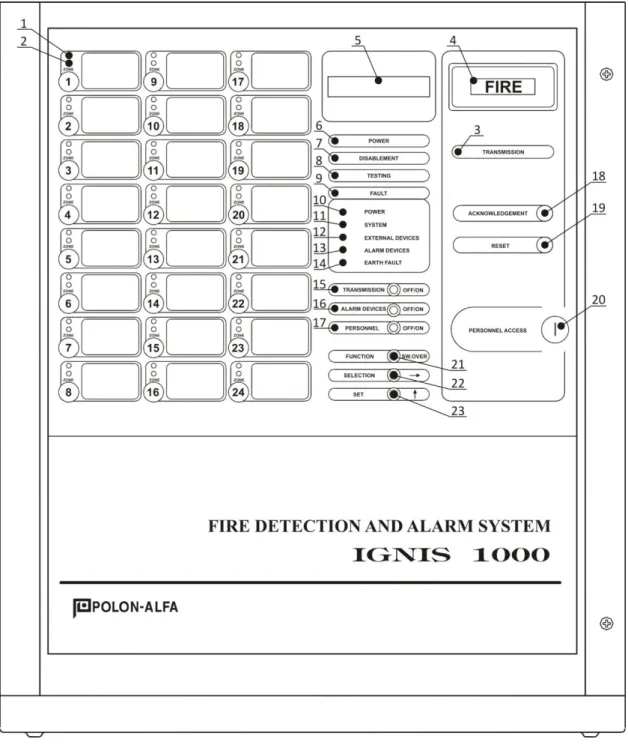
4.2.1 Handling elements and indicators on front panel
In the further part of this section, for easier identification, before the description of every element its number is given in the brackets according to the marking as in fig. 1.
The control panel front plate is equipped with signalling and handling elements presented in Fig. 1. Each element has its own text description. Particular element function and operation method is described below. Numbers corresponding with the descriptions used in Fig. 1 are given in brackets.
(1) 1…24 ZONE – red colour zone diodes assigned to 1…24 detection lines accordingly. The diode illuminates with continuous light, if fire detectors in the corresponding detection line are in the alarm mode. The illumination lasts from the moment when a signal from a detection line is identified as a fire alarm until the ACKNOWLEDGEMENT push button is pressed. The zone, where an alarm mode has occurred first, is signalled with flashing light; the following zones – with steady light.
(2) 1…24 ZONE – yellow colour zone diodes, allocated to 1…24 detection lines accordingly, indicate: with continuous light - the fault or testing mode (in the testing mode the diodes flashing
frequency is higher than in the fault mode),
with steady light – the disablement mode (line switch off), no light – the quiescent (supervision) mode.
(3) TRANSMISSION – a red colour diode signalling - with continuous light – the general alarm relay contacts switching in the active position.
(4) FIRE – a red colour display indicating a fire detection with flashing light (1 Hz frequency). The indicator has the FIRE wording and is lit during the control panel alarm mode. The indication changes for continuous light – after pressing the ACKNOWLEDGEMENT push button.
(5) LCD display – the displayed messages description is contained in p. 5.2.
(6) POWER SUPPLY – a green colour diode indicating that the control panel is connected to at least mains or battery power supply.
(7) DISABLEMENT – a yellow colour diode signalling collectively disablement of: at least one detection line,
signalling devices, or
alarm signal transmission (general alarm relays).
(8) TESTING – a yellow colour diode signalling the testing mode of at least one detection line;
(9) FAULT – a yellow colour diode indicating the fault mode (i.e. improper operation) of at least one circuit being under the control panel supervision. Five additional yellow diodes described below define which particular circuit is faulty.
(10) POWER SUPPLY – a yellow colour diode that signals: with steady light – a battery fault,
with flashing light – mains fault.
(11) SYSTEM – a yellow colour diode signalling with steady light a fault in the microprocessor circuit operation or a falsification of the configuration data.
(12) EXTERNAL DEVICES – a yellow colour diode that signals with steady light a fault of at least one detection line.
(13) SIGNALLING DEVICES – a yellow colour diode indicating with steady light a fault of at least one external signalling device.
(14) EARTH FAULT – a yellow colour diode signalling with steady light an earth fault of at least one control panel circuit (connected with the earthing potential).
(15) TRANSMISSION; OFF/ON – a yellow colour diode placed near the push button that signals with steady light the alarm relay disablement mode.
(16) SIGNALLING DEVICES; OFF/ON – a yellow colour diode placed near the push button indicates with steady light the disablement mode of external signalling devices. The signalling devices can operate only in the control panel fire alarm mode;
(17) PERSONNEL; OFF/ON – a yellow colour diode placed near the push button that signals with steady light the control panel ‘PERSONNEL ABSENT’ mode.
(18) ACKNOWLEDGEMENT – a push button for acoustic signalling devices silencing and a fire alarm receipt acknowledgement by the attending personnel; active at the 1st access level (without turning the key).
(19) RESET – a push button for the control panel or detectors in detector lines fire alarm mode reset; (20) PERSONNEL ACCESS LEVEL – a switch (a lock with a key) to actuate the handling elements designed for usage at the 2nd access level (all push buttons placed on the front panel).
(21) FUNCTION SW.OVER, (22) SELECTION, (23) SET – three push buttons enabling usage of the functions designated for the control panel parameters readout or change at the 2nd access level:
FUNCTION – a function selection,
SELECTION - moving the cursor to the right, SET - setting change.
4.2.2 Handling elements inside the control panel
Fig. 5 depicts the handling elements mounted on the STR-1240 controller board located inside the control panel:
(P1) FUNCTION, (P2) SELECTION, (P3) SET↑ and (P4) SET↓– four push buttons inside the control panel that enable usage of the functions dedicated to the control panel programming;
(P13) RESET - the control panel controller restart. Table 4
Jumper No. Jumper position Function
ZW1
1-2 Support of 16 detection lines – two line modules 2-3 Support of 24 detection lines – three line modules
ZW2
1-2 Unused
2-3 Unused
ZW3
1-2 2-3
ZW4 ZW10
Unused
2-3 Service mode without alarm receipt delays
ZW12
1-2
2-3 Software version display after pressing ACKNOWLEDGEMENT push button
Fig. 6 presents the view of the MZ-4212 power supply unit module that contains:
WŁ. AKU push button - used for switching the control panel on at the mains supply outage (essential when the batteries connection does not cause the control panel self-activation);
ZW1 jumper - enables disconnection the earth fault monitoring circuit and anti-interference modules from the casing;
ZW2 - a jumper enabling the earth fault monitoring circuit switch on/off; when the jumper is set in the position marked on the board - the earth fault monitoring circuit is switched on;
BZ1 – 3.15 A battery cluster circuit protection; the T3,15L250V type melt fuse;
BZ3 – 1 A external device power supply circuit protection; the F1L250V type melt fuse;
BZ2 – 1 A the control panel reserve internal circuits power supply output; (unused in the current version);
MAINS SWITCH - a two-pole mains power supply on/off switch.
5
CONTROL PANEL FUNCTIONALITY
5.1 LCD INDICATIONS AT 1ST AND 2ND ACCESS LEVEL SERVICING
The IGNIS 1240 control panel is equipped with a 16-character alphanumeric liquid crystal display (LCD). Its main function is to set and display the exact time and date, as well as the control panel configuration parameters. The current time and date are used by the automatic event recording system. Additionally, the LCD supports the panel operating personnel displaying information concerning the control panel status or the functions of activated push buttons.
During the control panel quiescent mode, the LCD displays the date and time. All other information, except the alarm mode, is displayed momentarily. After some seconds the control panel automatically switches to the date and time displaying mode.
1. Current date and time
- exemplary display:
(year-month-day hour:min)
2. Control panel alarm mode
The 1st and 2nd stage alarm
where:
- L1 – number of the line where the first alarm has been detected, - 0’00 – current fire alarm transmission delay time (0’00…9’59 range).
3. External signalling devices disablement/re-enablement
4. Alarm signal transmission disablement/re-enablement
5. Operation mode switch over between ‘personnel present’ and ‘personnel absent’
6. Fire alarm mode reset
7. Access denied
The above information is displayed in the case a function (push button) actuation trial without appropriate access level obtaining.
5.2 CONTROL PANEL FUNCTIONS AT 2ND ACCESS LEVEL
With the FUNCTION, SELECTION→,SET↑ push buttons available on the front panel it is possible to: set the date and time,
switch a zone or zones in the testing mode, disable/re-enable a zone or zones,
faults readout,
disable/re-enable all zones simultaneously.
L.1 ALARM ! 0’00
SIGN.DEV. ON
SIGN.DEV. OFF
TRANSMISSION ON
TRANSMISSION OFF
PERSONNEL PRESENT
PERSONNEL ABSENT
RESET
A desired function recall is performed using the FUNCTION push button. The item that can be modified is distinguished by the flashing tag. The tag location can be changed with the help of the SELECTION→ push button. The selected value modification is possible using the SET↑ push button.
5.2.1 Current date and time setting
(year-month-day hour:min)
The current date and time setting should start from entering the ‘date and time setting’ function using the FUNCTION push button. The LCD display shows a date with the first digit (tens of years) flashing. The digit flashing means that it is possible to alter its value with the SET push button. The SELECTION push button pressing moves the cursor to the next digit. In this way it is possible to set all the digits representing the current date and time (e.g. 03-12-31 23:59).
The SELECTION push button enables moving the cursor only to the right. A return to the beginning of the display is possible after passing all the digit positions. The SET↑ push button acts similarly. The control panel is equipped with a lithium battery mounted on the controller board that supports the clock in the case of power supply voltage outage.
5.2.2 Zone (detection line) testing mode disablement/re-enablement
The below described function allows for a zone testing mode disablement/re-enablement:
zone number 1…16 or 24
0 – testing enabled
1 – testing disabled
TESTING ON z. 01 - 0
5.2.3 Zone disablement/re-enablement
A disablement/re-enablement of a zone (detection line) is possible using the following function:
zone number 1…16 or 24
0 – zone enabled
1 – zone disabled
ZONE ON z. 01 - 0
02-12-31 23:59
5.2.4 Faults readout
In order to read the faults out, it is necessary to select with the FUNCTION push button the following indication on the display:
Afterwards, using the SET↑ push button recall the messages informing on the current faults registered in the system.
The below table lists the possible faults with their clarifications.
BZ3 FUSE FAULT BZ3 fuse fault
BATT.VOLTAGE DECR. Battery voltage drop
MAINS POW.SUP.FAULT 230 V mains power supply fault BATTERY FAULT Battery cluster or its circuit fault
EARTH FAULT Damage of insulation between control panel and grounding
LACK OF CHARGING Charging circuit fault of interruption SYSTEM FAULT Control panel controller program execution
disruption
CONFIG.SET. FAULT Disruption in configuration settings saved in control panel memory
CH. L 1 FAULT Fault in detection line 1 circuit CH. L 2 FAULT Fault in detection line 2 circuit CH. L 3 FAULT Fault in detection line 3 circuit
SDL 1 FAULT Fault in alarm signalling devices line 1 circuit SDL 2 FAULT Fault in alarm signalling devices line 2 circuit SDL 3 FAULT Fault in alarm signalling devices line 3 circuit BREAK OF LINE 1 Break in detection line 1 circuit
BREAK OF LINE 2 Break in detection line 2 circuit .
. .
. . . BREAK OF LINE 24 Break in detection line 24 circuit
SHORT OF LINE 1 Short circuit in detection line 1 circuit SHORT OF LINE 2 Short circuit in detection line 2 circuit
. . .
. . .
SHORT OF LINE 24 Short circuit in detection line 24 circuit LACK OF FAULTS No fault detected in IGNIS system
5.2.5 Disablement/re-enablement of all zones simultaneously
X – no changes
1 – all zones disabled
0 – zones enabled
ZONES ON OFF - X
Note:
Disablement or re-enablement of all zones takes place after typing 0/1 and the control panel restart using the RESTART push button inside the device.
5.2.6 Alarm counter readout
In order to read the alarm counter out, it is necessary to select with the FUNCTION push button the following indication on the display (the pictures illustrate the counter exemplary indication):
(alarm number zone number year—month-day)
The zone number informs about the alarm source and is consistent with the detection line number (1…24).
The display shows the latest alarm number, number of the zone where the alarm occurred, and its date. It is possible to read the alarm occurrence time with 1-second accuracy by pressing the SELECTION push button; then in the date place the alarm time is displayed as shown below:
(alarm number line number hour-minute-second)
Pressing the SELECTION push button produces alternate display of the clock time and date.
Preceding alarms readout is possible with the counter ‘scrolling’ using the SET↑ push button. The return to the latest alarm takes place after aborting the function by pressing the FUNCTION push button and selection of the alarm counter readout function again.
0001 z2 07 – 09 - 31
5.3 CONTROL PANEL FUNCTIONS AT 3RD ACCESS LEVEL
It is possible to use the functions available at the 3rd access level after the control panel door opening – Fig. 5. The P1-FUNCTION, P2-SELECTION, P3-SET↑ and P4-SET↓ push buttons located inside the control panel allows for the following functions application:
external signalling devices operation option setting, general alarm signal transmission delay value setting, event memory reset,
general alarm signal transmission delay disablement/re-enablement, alarm variants programming,
relays programming.
A desired function recall is performed using the FUNCTION push button. The item that can be modified is distinguished by the flashing tag. The tag location can be changed with the help of the SELECTION→ push button. The selected value modification is possible using the SET↑ and SET↓ push buttons.
5.3.1 Alarming lines (signalling devices) operation option setting
0 – sign. dev. operation acc. to 0 option 1 – sign. dev. operation acc. to 1 option
EXT.AL.OPTION - 0
The description of the signalling devices operation in option 0 and 1 is contained in p. 5.10.
5.3.2 General alarm relays actuation delay programming
1’30 – delay time (example) 1’ – minutes (1…9)
30 – seconds (0…59)
DELAY - 1’ 30
The delay time setting change is possible with the following push buttons: SET↑ - increase
5.3.3 General alarm signal transmission delay disablement/re-enablement
zone number 1…16 or 24
1 – delays enabled
0 – delays disabled
DELAYS ON z. 01 - 1
The setting change - with the SET↑ and SET↓ push buttons.
The function requires, apart from selecting the zone number (1…16 or 24), entering ‘1’ – if the delay is to be enabled or entering ‘0’ – if the delay is to be disabled. It allows for delay disablement of chosen detection lines, any alarm from which should actuate the general alarm relays immediately (e.g. a detection line with ROP manual call points installed). Any detecting line acknowledged alarm with a delay enabled (which value is set using the DELAY function) causes properly delayed general alarm relay activation. Lack of alarm acknowledgment shortens the delay time to 30 s. In the ‘personnel absent’ mode the control panel reduces the delay time to zero. The described delay concerns only the general alarm relays; zone relays operate always without any delay.
The general fire relay activation transmission delay programming is linked with alarm variant programming (see p. 5.3.6).
5.3.4 Event memory reset
0 – reset function disabled 1 – reset function enabled
MEMORY RESET - 0
Note:
The event memory reset performance is possible after the reset function initiation with the SET↑ push button and pressing the (P13) RESET push button.
5.3.5 ‘Standard configuration’ loading
0 – loading function disabled 1 – loading function enabled
STAND. CONF. - 0
Note:
The Standard configuration loading is possible after the loading function initiation with the SET↑ push button and pressing the (P13) RESET push button.
5.3.6 Alarm variants programming
zone number 1…16 or 24
1 – alarm variant number
(0, 1 or 2)
VARIANT z. 01 - 1
The setting change - with the SET↑ and SET↓ push buttons.
Note:
The variant 2 (zone interdependence) loading takes place automatically in both detection lines constituting the interdependent pair.
One-stage alarm
Programming:
- using the FUNCTION push button, select the function
- with the SELECTION and SET push buttons, choose the proper zone number and variant number equal to ‘0’
- using the FUNCTION push button, select the function
- with the SELECTION and SET push buttons, choose the proper zone number and ‘0’ (on the last display position) that results in the chosen zone delay disablement.
Two-stage alarm
Programming:
- using the FUNCTION push button, select the function
- with the SELECTION and SET push buttons, choose the proper zone number and variant number equal to ‘0’
- using the FUNCTION push button, select the function
- with the SELECTION and SET push buttons, set the proper delay time in minutes (0..9) – the X position in the display and in seconds (00…59) – two following positions XX.
Note:
The delay value set is common for all zones.
VARIANT z. 01 - 0
DELAYS ON z. 01 - 0
VARIANT z. 01 - 0
- using the FUNCTION push button, select the function
- with the SELECTION and SET push buttons, choose the proper zone number and ‘1’ (on the last display position) that results in the chosen zone delay disablement.
One-stage alarm with a preliminary reset
Programming:
- using the FUNCTION push button, select the function
- with the SELECTION and SET push buttons, choose the proper zone number (z. 01) and variant number - ‘1’
- using the FUNCTION push button, select the function
- with the SELECTION and SET push buttons, choose the proper zone number and ‘0’ (on the last display position) that results in the chosen zone delay disablement.
Two-stage alarm with a preliminary reset
Programming:
- using the FUNCTION push button, select the function
- with the SELECTION and SET push buttons, set the proper zone number and variant number equal to ‘1’
- with the SELECTION and SET push buttons, set the proper delay time in minutes (0..9) – the X position in the display and in seconds (00…59) – two following positions XX.
Note:
The delay value set is common for all zones.
- using the FUNCTION push button, select the function
- with the SELECTION and SET push buttons, set the proper zone number and ‘1’ (on the last display position) that results in the chosen zone delay enablement.
DELAYS ON z. 01 - 1
VARIANT z. 01 - 1
DELAYS ON z. 01 - 0
VARIANT z. 01 - 1
DELAY X’ XX’’
Two-stage alarm with zone-time interdependence
Programming:
- using the FUNCTION push button, select the function
- with the SELECTION and SET push buttons, set the number of one of the interdependent zones and variant number equal to ‘2’,
- using the FUNCTION push button, select the function,
- with the SELECTION and SET push buttons, set the proper delay time in minutes (0..9) – the X position in the display and in seconds (00…59) – two following positions XX.
Note:
The delay value set is common for all zones.
- using the FUNCTION push button, select the function,
- with the SELECTION and SET push buttons, set the number of the first interdependent zone and enter ‘1’ (on the last display position) that results in the chosen zone delay enablement, - repeat the above operation for the second zone of the interdependent zones pair so that each
zone (of the pair) has the delay enabled.
Note:
Entering the variant #2 for any zone results in an automatic creation of a dependent zone pair and automatically assigns the variant #2 to the second zone constituting the pair. Similarly, a failure to choose the variant #2 and assigning the variant #0 or #1 to a zone constituting the pair results in an automatic loading of the variant #0 for the other zone of the pair.
It is possible to create interdependent zone pairs using only zones of neighbouring numbers as shown below:
- 1st pair – zones #1 and #2 - 2nd pair – zones #3 and #4 - 3rd pair – zones #5 and #6 - 4th pair – zones #7 and #8
- ………..
- 12th pair – zones #23 and #24.
-In case another pair of interdependent zones should be formed, it is necessary to change places of the detector lines connection on the clamp board.
Two-stage alarm with zone-time interdependence
The control panel operation is same as in the preceding alarm variant with one exception: a 1st stage alarm is omitted and a 2nd stage alarm is evoked immediately.
VARIANT z. 01 - 2
DELAY X’ XX’’
In the programming process it is necessary to repeat the operations from the preceding description with the exception of the ‘delay on’ function, where the particular zone delay should be disabled as shown below:
5.3.7 Zone relay programming
12 – zone number 1…16 or 24
- -
no relay assignedor ‘RES’ reset – relays act
- -
no relay assignedonly during alarm reset
*
-
number of relay assigned to reset function 12 – number of zone relay 0…16 (24)12 P: 12 * - -
The function enables:
- to assign to each of 16 (24) zones 0…4 zone relays that will switch the contacts over when a given zone enters the alarm mode; the same relay can be assigned to different zones; the contacts return to the rest position takes place after the control panel alarm mode reset; - to program 0…4 zone relays actuation is such the manner that the contacts switchover takes
place during the alarm mode reset and this relay actuation is not dependent on the alarm mode and reset.
Appearance of ‘*’ instead of a relay number means that this relay has already been assigned to the reset function.
Example 1:
The above setting means that in the alarm mode of the fourth zone, the relays marked as 4, 16 and 20 will be actuated.
The above setting means that during the control panel alarm mode reset, the contacts marked as 1 and 17 will be switched over. After a reset the contacts return to the previous position.
5.4. QUIESCENT (SUPERVISION) MODE
In the quiescent mode, i.e. when the control panel waits for a signal from fire warning devices, only a green colour POWER (6) diode is lit on the front panel informing that the control panel is power supplied. Additionally, the LCD (5) displays the current time and date.
General fire alarm relays and zone relays are inactive and the general fault relay is in an operating mode.
DELAYS ON z. 01 - 0
04 P: 4 16 20
5.5. ALARM MODE 5.5.1 Fire alarm signalling
The following indications can be seen on the control panel front side during the fire alarm:
- one of the ZONE 1…24 red zone indicating diodes switches on; the first zone where a fire has occurred is distinguished with flashing light, all others are lit with steady light;
- the general alarm display, with a FIRE communique, flashes;
- a fire alarm message, indicating the zone number where the first alarm occurred and the elapsing time remaining until general fire alarm relays are activated, appear on the LCD;
- an internal acoustic signalling device is switched on, operating with an interval of 0.5 s/0.5 s signal.
The acoustic signal (internal and external) can be silenced at the 1st access level by pressing the ACKNOWLEDGEMENT push button (option 0) or only the internal one (option 1). The 1st stage alarm duration can be programmed in the 0…10 min. range and its countdown can be stopped by the transmission disablement with the help of the TRANSMISSION push button (2nd access level). Lack of the 1st stage alarm acknowledgement shortens the delay time to 30 seconds. After the delay time elapse (without transmission disablement), the control panel evokes the 2nd stage alarm.
5.5.2 Fire alarm verification by the attending personnel
The control panel enables an occurrence verification by the personnel in case a fire alarm has been revealed. It is required that the attending person approaches the panel and confirms an alarm receipt within 30 seconds by pressing the ACKNOWLEDGEMENT push button. In case the person on duty fails acknowledgment within the given time period, the control panel initiates an alarm transmission outside without any delay, i.e. to a monitoring centre or to the fire brigade. After the fire alarm receipt acknowledgment, the person on duty is given an additional time, with a programmable length, for recognition of a real fire threat in the premises.
The elapsing time left for the alarm acknowledgment and for the threat recognition is displayed on the LCD (5).
In the case of a false alarm or when a threat does not exist, the person should reset the light signal with the RESET push button. This operation is effective when no fire factor is present in the vicinity of the fire warning device that has evoked the alarm and the 2nd access level is available.
5.5.3 Automatic alarm signal verification, alarming variants
The control panel possesses a wide range of possibilities to verify fire signals coming from fire warning devices. Recognition of a received signal as a fire alarm is preceded by multiple checking readout and analysis of the signal received from the detection lines. Moreover, it is a possible to program the following alarm variants for every detection line:
one-stage alarm; two-stage alarm;
one-stage alarm with a preliminary reset; two-stage alarm with a preliminary reset;
two-stage alarm with zone-time interdependence one-stage alarm with zone-time interdependence.
One-stage alarm
A line element actuation immediately evokes the general fire alarm (of the 2nd stage) – switching the general alarm transmission relays on. This variant is applicable especially in the case when a fire signal comes from manual call points which are treated as an unquestionable information source.
Two-stage alarm
The general alarm (of the 2nd stage) – switching the alarm transmission relays on – takes place after a programmable delay time (0…10 min). A line element actuation is signalled optically and acoustically until the personnel on duty confirms its presence and acknowledge the 1st stage alarm (with the ACKNOWLEDGEMENT push button). Lack of the personnel attendance confirmation and the alarm acknowledgement within 30 s evokes a general alarm: the alarm transmission relays are switched on. The personnel attendance confirmation and the alarm acknowledgment before the 30-s time elapse, delays the main alarm according to the settled delay time (0…10 min), what enables recognition of the occurred fire threat.
One-stage alarm with a preliminary reset
This method consists in an immediate reset of a detector line alarm mode after a detector actuation and detecting an alarm by the control panel, without any information transmission to the signalling circuits. A repeated actuation of any detector in the same detector zone (line) within 60 s will be treated as the general (2nd stage) fire alarm. Lack of a repeated actuation of the same or another element in the same zone within the 60-s period after the initial reset will entail that the control panel treats the previous signal as false and returns to the quiescent mode.
Two-stage alarm with a preliminary reset
The only difference between this variant in comparison with the previous one is that after the second actuation of a fire detector the 1st stage fire alarm is evoked. The general alarm transmission relays are switched on only after the set delay time lapse.
Two-stage alarm with zone-time interdependence
After an actuation of a line element that belongs to one of two interdependent zones, the control panel awaits consecutive signals without a fire alarm evoking. In case a line element installed in the other zone, constituting the interdependent zone pair, actuates within 60 s after the first actuation, the control panel evokes the 1st stage alarm; after the set delay time lapse – evokes the 2nd stage alarm. Lack of the actuation of the element in the other zone within 60-s period will entail that the control panel treats the previous signal as false, automatically resets the alarming fire detecting device and returns to the quiescent mode.
One-stage alarm with zone-time interdependence
The control panel operation is same as in the preceding alarm variant with one exception: the 1st stage alarm is omitted and the 2nd stage alarm is evoked immediately.
5.6. FAULT MODE
The fault mode is signalled by the control panel in case of the following fault detection: - a break of or a short circuit in any detection line;
- a break of or a short circuit in any monitoring line;
- a break of or a short circuit in external acoustic signalling device lines; - a mains power supply fault;
- a battery fault resulting from its internal resistance increase above 2 Ω or a lack of a battery; - a battery charging device fault;
- a break in the charging circuit; - a BZ3 fuse lack or its insert burn-out; - a microprocessor system fault;
- an earth fault, i.e. connection of any control panel circuit with the control panel metal casing or with the grounding.
The fault mode is signalled by the control panel generally by the yellow FAULT (9) diode and by yellow (10…14) diodes that indicate the fault type, as well as by an acoustic fault signal. Detailed information concerning the fault type is available on the LCD after selecting the FAULT READOUT function utilising the FUNCTION (21) and SET↑ (23) push buttons. Silencing of the sound signal is possible at the 1st access level by pressing the ACKNOWLEDGEMENT push button. A reset of light signalling proceeds automatically after the fault removal. The only exception is a serious fault of the microprocessor controller which cannot be silenced, due to its importance, with the ACKNOWLEDGEMENT push button. A system fault resulting from false configuration data can be silenced with the ACKNOWLEDGEMENT push button but in such the case it is necessary to check the control panel configuration settings and, eventually, correct them. If the signalling still persists, after such checking/correcting, it means that the control panel is damaged. It is necessary to switch the control panel power supply off and call the service personnel.
5.7 DISABLEMENT MODE
In the control panel it is possible to disable:
- every zone (equivalent with the detection line power supply disconnection);
- the relay of alarm signal transmission to the monitoring centre or to external devices; - the external signalling device line.
Disablement and re-enablement is possible at the 2nd access level. After a disablement, the general DISABLEMENT (7) diode is lit as well as the appropriate diodes of the disabled circuit:
- ZONE 1…24 (2) in the zone field, - TRANSMISSION (15),
- SIGNALLING DEVICES (16).
A zone disablement is equivalent with a detection line disablement; the detectors installed in the disabled detection line, are left without power supply voltage.
5.8 TESTING MODE
The control panel allows for testing fire detectors in detection lines by actuating them with e.g. fire factor imitators. Switching a zone into the testing mode is possible utilising the TESTING ON function at the 2nd access level. This function initiation is possible with the FUNCTION (21) push button. During the testing mode, the TESTING (8) diode is lit and a yellow diode indicating the tested line (zone)
flashes. A tested detector, after its actuation, signals an alarm within ca. 8 s, and afterwards the detection line is automatically reset.
An inspection of all control panel signalling elements can be carried out after pressing the PERSONNEL – OFF/ON push button and holding it for more than 3 s at the 1st access level.
5.9 SIGNAL TRANSMISSION/AUXILIARY EQUIPMENT CONTROLLING
The control panel is able to control protecting devices or transfer fire alarm signals to a monitoring station using the relay outputs that are activated during a fire alarm. The general alarm relay operation may be delayed or immediate. The delay is programmable in the 0 to 9 min 59 s range, with 1-s step. Individually, for each detection zone, the delay can be disabled or enabled. The delay enablement is additionally dependent on the PERSONNEL OFF/ON push button status and the alarm acknowledgement. If the control panel is in the PERSONNEL ABSENT mode, the delay time is shortened to zero. When the control panel operates in the PERSONNEL PRESENT mode, the delay time is shortened to 30 s if the alarm is not acknowledged by the ACKNOWLEDGE push button pressing.
The zone relays are not furnished with a direct possibility of the delay time programming, they operate immediately after an alarm detection but it is possible to assign them individually to a particular zone. The relays that are assigned to a zone switch the contacts over only in the zone alarm mode. The relay programming is described in p. 5.3.7.
5.10 ACOUSTIC SIGNALLING DEVICES
Besides the internal sound signalling device, being activated in the case of an alarm or fault, the control panel offers a possibility to connect, via monitored controlling lines, external acoustic signalling devices. Those devices can be disabled and re-enabled by the SIGNALLING DEVICES – OFF/ON (16) push button, but the push button operation depends on programmable “0” or “1” option for a given line. In case the “0” option is programmed, in the alarm mode the ACKNOWLEDGEMENT push button silences both internal and external sound signalling. At the same time the SIGNALLING DEVICES (16) push button can disable and re-enable the external signalling devices (without obtaining the 2nd access level). In case the control panel receives an alarm signal from another zone, the internal and external acoustic signalling is repeated.
If the “1” option is programmed, the external signalling device lines can be used as a fire fighting equipment controlling line. Then the SIGNALLING DEVICES (16) push button, allowing this line disablement, operates only at the 2nd access level. Usage of the ACKNOWLEDGEMENT push button does not influence the line, utilised in this way; also a following alarm will not unblock this output. The SIGNALLING DEVICES (16) diode illumination indicates the external signalling devices silencing (“0” option) or the controlling line disablement (“1” option).
5.11 EXTERNAL DEVICE OPERATION INSPECTION
The control panel is equipped with two or three monitoring lines designed to inspect operation of the connected external devices. The contacts of relays (closed - during proper operation) or switches of the devices that are controlled should be in a series connected to such a line. Any device fault that results in opening of the monitoring contact, or any fault of the line itself (a break or short circuit),
evokes the fault mode signal in the control panel. Every monitoring line must be terminated with a 10 kΩ resistor as it is shown in the below figure.
5.12 CONTROL PANELS PARALLEL OPERATION
Fig. 8 presents the connection method of a common sound signalling device to two control panels and possibility to transmit a common alarm and fault signal to the monitoring system.
In the case of an acoustic signalling device of resistance > 10 kΩ, the control panels can indicate an external devices fault. In such the case it is necessary to install additionally loading resistors of 10 kΩ resistance in parallel to each LA line. In order to supervise properly the alarm lines status, the resistors should be connected at the lines ends, close to the acoustic signalling device.
The acoustic signalling device silencing during the alarm mode is possible from the control panel that has evoked the alarm.
6
POWER SUPPLY
6.1. BASIC POWER SUPPLY
The control panel is primarily supplied by 230 V/50 Hz mains. A voltage alteration within +10 % and -15 % range does not influence the control panel proper operation.
6.2. RESERVE POWER SUPPLY
In case of mains voltage outage, the control panel is supplied from reserve battery cluster of 24 V nominal voltage and 17 Ah capacity. A switch-over from the main power supply to the reserve one is carried out automatically, without any break in power supply. The control panel, supplied from the batteries only, without any additional device power consumption, is able to operate within 72 h in the quiescent mode and + 0.5 h in the alarm mode. The control panel may operate being supplied from a battery cluster of higher capacity – up to 36 Ah. In this case the battery cluster should be located as close to the control panel as possible, the connecting cables should be of resistance lower than 0.5 Ω and the internal batteries should be disconnected. Parallel batteries operation is allowed only in the case of the same electrical parameters.
The external batteries enable connection of additional devices that consumes current during the control panel quiescent mode. The battery cluster is charged automatically by the control panel power supply unit.
The efficiency of both the batteries and charging device is constantly monitored and any fault is being signalled. The battery is recognised as inoperative when its internal resistance increases and exceeds 2 Ω.
Power consumption from a battery. In the quiescent mode, without the basic power supply, with the full quantity of fire warning devices in 24 detection lines, but without additional device power supply, the control panel current consumption does not exceed 228 mA.
Automatic power supply switch-off. During the control panel operation, being power supplied only from a battery cluster, the battery voltage progressively decreases. A reserve power supply voltage drop down to ca. 22 V is acoustically signalled. Further decline in the battery panel voltage and achieving 21 V level will result in the control panel automatic switch-off. In an alarm mode this function is disabled. The power supply renewed switch-on, after a properly charged battery re-connection, may require (in case the basic power supply is not restored automatically) pressing of the P1 WŁ.AKU push button which is available after opening the control panel door on the MZ-4212 power supply module board. The basic power supply restoring during operation with the reserve power supply will automatically switch over the control panel to the basic one.
Note:
The battery installation, operation and waste-disposal must be carried out pursuant to the manufacturer’s manual. A waste battery must be delivered to a proper collecting and recycling point in accordance with the law in force.
7
INSTALLATION
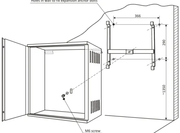
7.1 CONTROL PANEL MOUNTING
The control panel should to be mounted on a wall using a special steel hanger and four expansion anchor bolts of minimum diameter at 8 mm. The spacing of the fastening bolt holes is shown in Fig. 3. The control panel mounting shall be executed only without batteries.
7.2 WIRING
Detection, monitoring and controlling lines should be routed according to the commonly applicable principles used in telecommunications. They can be placed on walls under the plaster, in the ground or as overhead lines. The lines must be continuous and terminated with end-of-line resistors. Before the wire connection it is necessary to check whether the conductors resistance is not exceeded and turn attention to the proper wire polarization ‘+’ and ‘-‘.
It is recommended to use certified conductors of 0.8 or 1.0 mm diameter. In order to eliminate electromagnetic interferences, the screen continuity must be provided in the bases connection. The detector line wires can be inserted into the control panel from the installation, being led either on or in wall plaster. They are introduced into the control panel upper part through round bushings. The mains supply wires are led through an opening located in the control panel bottom part, in accordance with Fig. 6. The 230 V/50 Hz mains wires should be connected (after removing a covering plate) to the purposely marked mains supply terminals. The control panel can be used only with an application of additional electric shock protection, in a form of protective conductor. Due to the control panel higher interference resistance it is recommended to use grounding protection.
8
COMMISSIONING AND CONFIGURATION
8.1 COMMISSIONING
The following operations are recommended before the control panel commissioning:
to check all installation work correctness and remove possible discrepancies, first of all short circuits and breaks;
to measure resistance of detection, monitoring and alarm lines and compare with admissible values;
to check the wires polarization (‘+’, ‘-‘) with the terminal descriptions in the control panel; to check presence of end-of-line resistors on unused line clamps in the control panel
(detection lines – 5.6 kΩ; monitoring lines – 10 kΩ); to measure the grounding resistance;
to check the programming jumper positions – see p. 7.2.2, Table 4. After the control panel operation start, it is recommended to:
in the case of a fault mode signalling – silence the control panel by pressing of ACKNOWLEDGEMENT push button and read out FAULTS in accordance with 5.2.4;
remove possible faults so that the control panel signals the quiescent mode and lack of faults;
use programming functions described in p. 5.2 and p. 5.3 to configure the control panel, set the current time and date;
test signalling diodes placed on the control panel doors – p. 5.8;
use the TESTING ON function to test fire detectors and manual call points;
check operation of the control panel, signalling devices and alarm devices after the alarm mode evoking;
check operation of other external devices installed in the system;
measure voltage on battery clamps (in buffering mode – lack of LED indication on the power supply module – voltage should amount to 27.1 27.6 V;
reset the event memory – p. 5.3.4.
8.2 STANDARD CONFIGURATION LOADING
The IGNIS 1240 control panel is delivered to a customer with initially programmed operation conditions determined by the manufacturer, described as the ‘standard configuration’. The control panel programming by the customer changes the factory default settings optimally adapting its parameters to the system needs and protected premises features. The control panel is provided with a function that enables an automatic reset of the customer’s settings and a return to the standard configuration.
In order to load the standard configuration it is necessary to: - open the control panel (3rd access level);
- use the ‘standard configuration loading’ function in accordance with p. 5.3.5;
- select the following display indication: STANDARD CONF. – 0 using the internal FUNCTION push button (by pressing it several times repeatedly);
- enable the function by entering “1” with the SET↑ push button; - restart the control panel with the RESET push button.
The following control panel parameters are loaded after executing the above mentioned operations: all zones are enabled;
all zone delays are enabled; delay time is set at 1 min 30 sec;
all zones are assigned with the alarm variants of the 0 number; external alarm option – 0;
monitoring line operation option – 0;
every zone (line) is matched with one zone relay of the same number as the zone number; the relay actuation depends on the alarm mode in the zone;
the TRANSMISSION, SIGNALLING DEVICES, PERSONNEL push buttons are in ON position (lack of disablement).
9
SOFTWARE FOR EVENT MEMORY READOUT
9.1 EVENT MEMORY GENERAL DESCRIPTION
The IGNIS 1240 control panel is equipped with the memory of the events that took place during the premises supervision. The following occurrences are treated as events:
1. fire alarms;
2. all faults, detected by the control panel, and their removals; 3. acknowledgment of alarm and fault information receipt; 4. configuration settings change;
5. alarm reset;
6. zone switch-over for testing;
7. alarm transmission (general fire relay) activation;
8. disablement and re-enablement of alarm transmission / general fire relay. Every event message contains the event date and time with 1-second accuracy.
A special part of the memory, was separated from the entire panel memory and is intended only for fire alarms recording – they are recorded in the fire counter of 9,999-occurrence capacity. The alarm counter readout on the LCD is possible after obtaining the 2nd access level (as per description in p. 5.2.6). The event history printout is provided by the special software and a PC computer use.
Occurrences different from fire alarms (such as faults, disablements, configuration changes, etc.) are recorded separately. When the memory capacity of 512 occurrences is exceeded, new events are recorded at the memory beginning in the place of the oldest ones. The entire memory contents readout or printout is possible after sending the data from the control panel to a PC computer through the RS 232C serial port the control panel is equipped with. The data transmission takes place after activation of the event memory readout software. It is possible to delete the event memory contents using the function described in p. 5.3.4 at the 3rd access level. The alarm counter erasure needs a special key use at the 4th access level.
9.2. HARDWARE REQUIREMENTS
a) PC computer with Windows 98/ME/2000/XP/Vista/7 operating system equipped with: - accessible RS 232 (COM1 ÷ COM4 type) serial port;
- hard disc of ca. 0.5 MB free memory; - Internet connection.
9.3 CONTROL PANEL-COMPUTER CONNECTION
Before starting the program, a computer should be connected to the control panel. This operation should be carried out when the computer is switched off. A connecting cable should be ended with a 9-contact connector from the control panel side and a 9- or 25-contact connector from the other side.
In case an available cable is ended with 9-contact connectors on both sides and the computer is equipped with a 25-contact connector, it is possible to use an adapter available at IT accessories stores. On the below diagram it is shown how to connect the computer with the control panel when the computer is equipped with a 9- or 25-contact connector.
COMPUTER
COMPUTER
CONTROL PANEL CONTROL PANEL
Rxd Txd GND
Rxd Txd GND
9.4 SOFTWARE LAUNCHING AND EVENT MEMORY READOUT
The software necessary for the event memory readout and information materials are available on www.polon-alfa.pl web site after obtaining an access code.
After connecting the control panel to the computer, it is necessary to: - switch the computer on;
- copy the igniswin folder to a hard disk; - launch the igniswin.exe program;
- when a possibility to choose a serial port appears on the screen, select the number depending on which port the control panel is connected to;
- switch over the control panel to the 2nd access level (turning the key to a horizontal position); - start the event memory transmission pushing the ACKNOWLEDGEMENT push button at the control panel and holding it for about 5 s until the moment when the data transmission indicator, located on the computer screen, starts to be filled in;
- wait about 20 seconds until the data transmission is finished (the indicator is full).
The events will appear in a program ‘window’ ready for readout. In order to print the occurrence list out, the option ‘print’ should be chosen from the ‘file’ menu.