ISSN(Online): 2320-9801 ISSN (Print): 2320-9798
I
nternational
J
ournal of
I
nnovative
R
esearch in
C
omputer
and
C
ommunication
E
ngineering
(An ISO 3297: 2007 Certified Organization)
Vol. 4, Issue 2, February 2016
A Survey on Channel Estimation Algorithms
for LTE Downlink Systems
Khushboo A. Parmar1, Saurabh M. Patel2
ME Student, Dept. of E&C, Sardar Vallabhbhai Patel Institute of Technology, Vasad, Gujarat, India1
Asst. Professor, Dept. of E&C, Sardar Vallabhbhai Patel Institute of Technology, Vasad, Gujarat, India2
ABSTRACT: In order to achieve high data rate communication with mobility, Long Term Evolution (LTE) has been introduced. LTE Downlink systems adopt Orthogonal Frequency Division Multiple (OFDM) and MIMO to provide up to 100 Mbps (assuming a 2x2 MIMO system with 20MHz bandwidth). The performance gain of MIMO heavily depends on the accurate estimation of Channel State Information (CSI), which is crucial for every communications system. In this paper, we present different channel estimation algorithms for LTE Downlink systems . This include channel estimation using Pilot Symbols and Blind Channel estimation algorithms. The estimation techniques involved the Least Square Error (LSE) and the Minimum Mean Square Error (MMSE) is being studied and finally compared.
KEYWORDS: Long Term Evolution (LTE); Orthogonal Frequency Domain Multiple (OFDM); Multiple Input Multiple Output (MIMO); Channel Estimation; Pilot Symbol; Least Square Error (LSE); Minimum Mean Square Error (MMSE)
I. INTRODUCTION
To satisfy an increasing demand for high data rate with available limited spectrum for wireless communication, 3rd Generation Partnership Project (3GPP) introduces Long Term Evolution (LTE). LTE provides high data-rate, low latency and flexible bandwidth [1]. LTE offers a theoretical speed of 100 Mbits/s in the Downlink and 50Mbits/s in the Uplink transmission with 20 MHz bandwidth [2],[3]. LTE Downlink systems adopt Orthogonal Frequency Division Multiple (OFDM) and MIMO to provide up to 100 Mbps for 2x2 MIMO systems [3]. OFDM is used to combat the effect of frequency selective fading and can improve the spectral efficiency of the system [2],[3]. OFDM converts the frequency selective channel into parallel flat-fading sub-channels. MIMO system increases channel capacity and decreases the signal fading by sending the same information at the same time through multiple antennas [3].
In Mobile communication systems prior to transmit the information certain characteristics of the radio waves are changed in accordance with the information bits. At the receiving end the information bits are retrieved accurately, if the channel characteristics are known. The Channel State information (CSI) provides the known channel properties for a wireless link. It provides the effects of fading and scattering on a signal propagating through the medium. Normally the CSI estimated at the receiver fed back to the transmitter. If it is not estimated accurately at the receiver, leads to system degradation. It can be estimated by using different channel estimation algorithms. Many research works have studied for this MIMO-OFDM system. In this paper, we present different channel estimation algorithms for LTE Downlink systems.
This paper organized as follows. Section II contains related work of channel estimation on LTE Downlink system, section III provides the overview of LTE downlink systems, section IV describes the channel estimation of LTE downlink system and then section V explains most used channel estimation algorithms. Finally, the conclusion is specified in section IV.
II. RELATED WORK
ISSN(Online): 2320-9801 ISSN (Print): 2320-9798
I
nternational
J
ournal of
I
nnovative
R
esearch in
C
omputer
and
C
ommunication
E
ngineering
(An ISO 3297: 2007 Certified Organization)
Vol. 4, Issue 2, February 2016
transmitted OFDM symbol in order to mitigate both inter- carrier interference (ICI) and inter-symbol interference (ISI). Simulation results show that in the case where the CP length is equal to or longer than the channel length, the LMMSE performs better than LS estimator but at the cost of the complexity because it depends on the channel and noise statistics. In the other case, LMMSE provides better performance only for low SNR values and begins to lose its performance for higher SNR values. In other hand, LS shows better performance than LMMSE in this range of SNR values.
Simko et al. [4] investigated implementation aspects of the channel estimator in 3GPP LTE terminals. In this, the channel estimator presented boosts the throughput at feasible silicon by adopting estimation method named Approximate Linear Minimum Mean Square Error (ALMMSE). Simulation results show that the LMMSE channel estimator outperforms the LS and ALMMSE estimators. However, its hardware implementation requires the most computational power. It supports 20MHz downlink bandwidth.
Coleri et al. [5] compare the performance of all the estimation schemes by applying 16QAM, QPSK, DQPSK BPSK with Rayleigh fading and AR (Auto-Regressive) based fading channels for OFDM symbols based on training based channel estimation. For that they have used LS, MMSE and LSE algorithms. Their simulation results show that comb-type pilot based channel estimation with low pass interpolation performs the best among all channel estimation algorithms.
Zaier and Bouallègue [6] perform a blind channel estimator based on a subspace approach in a MIMO OFDM for a high mobility scenario. The simulations results have demonstrated the effectiveness of the approach for a 16 QAM modulation scheme and had been evaluated in term of bit error rate BER and mean square error MSE versus the signal to noise ratio SNR.
Bouchibane et al. [7] proposed a novel optimal pilots design for SISO-OFDM system by maintaining the same average power in pilot symbols and the data symbols but varying the distance between the pilots. Simulation results show that Equi-powered and equi-spaced pilot-symbols lead to the lowest MSE and maximize the channel capacity. The pilot symbols spacing gives best performance in terms of BER.
III.OVERVIEW OF LTEDOWNLINK SYSTEM
A. OFDM-MIMO Transmission Model:
LTE Downlink systems adopt Orthogonal Frequency Division Multiple (OFDM) and MIMO to provide up to 100 Mbps.
Fig.1 OFDM-MIMO System Model [8]
In figure 1, serial data input is X is given as an input to the transmitter. We consider here that MIMO system has N numbers of transmitters and receivers. The serial data X is first converted into the parallel streams x1,x2,x3,...,xk. After
ISSN(Online): 2320-9801 ISSN (Print): 2320-9798
I
nternational
J
ournal of
I
nnovative
R
esearch in
C
omputer
and
C
ommunication
E
ngineering
(An ISO 3297: 2007 Certified Organization)
Vol. 4, Issue 2, February 2016
N{X(k)} into time-domain signal {x(n)}. Then the parallel data stream is converted back to the serial data and guard interval is inserted between successive OFDM symbols to avoid the Inter Symbol Interference (ISI). If a guard interval with no signal transmission is inserted then the ISI can be eliminated almost completely, but a sudden change of waveform contains higher spectral components, so they result in Inter Carrier Interference (ICI). To avoid the Inter Carrier Interference (ICI), a guard interval with cyclic prefix is generally used. A copy of the last part of the OFDM symbol is attached to its front is called a Cyclic Prefix (CP). The transmitted signal xf(n) will pass through the
frequency selective time varying fading channel with additive noise. The received signal is given by [9]:
yf(n) = xf(n) O h(n) + w(n) eq.(1)
Where, w(n) is additive white Gaussian noise and h(n) is channel impulse response.
At the receiver, after passing to discrete domain through LPF, guard time is removed. Then y(n) is sent to FFT block to recover the time domain signal [9].
Y(k) = X(k)H(k) + I(k) + W(k) , k=0,1,...N-1 eq. (2)
Following FFT block, pilot signals are extracted and estimated channel He(k) for the data sub-channels is obtained
in channel estimation block. Then the transmitted data is estimated by [9]: Xe =
( )
( ) , k=0,1,2,...,N-1 eq.(3) Then the binary information data is obtained back in “signal demapper” block.
B. Cyclic Prefix (CP):
Insertion of cyclic prefix is an important function during OFDM signal generation. A cyclic prefix is necessary to prevent interference from previously transmitted OFDM symbols. The length of the cyclic prefix must be sufficient to cover typical delay spreads encountered in most propagation scenarios within a cellular environment. LTE specifies the cyclic prefix length as the expected delay spread of the propagation channel and provides a margin for error to account for imperfect timing alignment [8].
Table 1. Cyclic prefix specifications
Configuration Sub-carrier spacing (∆f)(KHz) No. of subcarriers per resource block
No. of OFDM symbols per resource
block
Normal CP 15 12 7
Extended CP 15 12 6
As shown in Table 1, the LTE standard specifies two different cyclic prefix values [4]: (i) normal (4.7 μs) and (ii)
extended (16.6 μs) for subcarrier spacing of 15 kHz. The normal cyclic prefix length of 4.7 μs is appropriate for
transmissions over most urban and suburban environments and reflects typical delay spread values for those environments.
C. LTE Physical Layer:
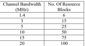
LTE has a spectrum allocation ranging from 1.4MHz to 20MHz. The frequency spectra in LTE are formed as concatenations of resource blocks consisting of 12 subcarriers, which is referred as Physical Resource Block (PRB). Since subcarriers are separated by 15 kHz, the total bandwidth of a resource block is (12 x 15 KHz =) 180 kHz. This enables transmission bandwidth configurations of from 6 to 110 resource blocks over a single frequency carrier.
Table 2. Channel bandwidths specified in LTE
Channel Bandwidth (MHz)
No. Of Resource Blocks
1.4 6
3 15
5 25
10 50
15 75
ISSN(Online): 2320-9801 ISSN (Print): 2320-9798
I
nternational
J
ournal of
I
nnovative
R
esearch in
C
omputer
and
C
ommunication
E
ngineering
(An ISO 3297: 2007 Certified Organization)
Vol. 4, Issue 2, February 2016
According to 3GPP specifications the time-domain structure of the LTE is illustrated in figure 2 & figure 3.
LTE Frame radio = 10ms
Subframe=1ms
0
1
2
3
………. 18 19
6 OFDM symbols
1 2
3
4
5 6
Cyclic Prefix
Fig.2. LTE Radio Frame
In the time domain, LTE organizes the transmission as a sequence of radio frames of length 10 ms. Each frame is then subdivided into 10 subframes of length 1 ms. Each subframe is composed of two slots of length 0.5 ms each. So it is composed of 20 slots of 0.5 ms. Finally, each slot consists of a number of OFDM symbols, either seven or six depending on whether a normal or an extended cyclic prefix is used.
Fig.3. LTE Time-domain structure [8]
ISSN(Online): 2320-9801 ISSN (Print): 2320-9798
I
nternational
J
ournal of
I
nnovative
R
esearch in
C
omputer
and
C
ommunication
E
ngineering
(An ISO 3297: 2007 Certified Organization)
Vol. 4, Issue 2, February 2016
Fig. 4.Resource elements, blocks, and grid [8]
Figure 4 shows the LTE downlink resource grid when a normal cyclic prefix is used. A resource element is placed at the intersection of an OFDM symbol and a subcarrier. The subcarrier spacing is 15 kHz and, in the case of normal cyclic prefix, there are 14 OFDM symbols per subframe or seven symbols per slot. A resource block is defined as a group of resource elements corresponding to 12 subcarriers or 180 kHz in the frequency domain and one 0.5ms slot in the time domain. For normal cyclic prefix with seven OFDM symbols per slot, each resource block consists of (12 subcarriers x 7 OFDM symbols =) 84 resource elements. For extended cyclic prefix with six OFDM symbols per slot, the resource block contains (12 subcarriers x 6 OFDM symbols =) 72 resource elements [3]. A Physical Resource Block (PRB) represents the smallest unit of transmission that is subject to frequency-domain scheduling.
slot slot
sub-frameISSN(Online): 2320-9801 ISSN (Print): 2320-9798
I
nternational
J
ournal of
I
nnovative
R
esearch in
C
omputer
and
C
ommunication
E
ngineering
(An ISO 3297: 2007 Certified Organization)
Vol. 4, Issue 2, February 2016
In LTE standard pilot symbols are inserted at specific position in each PRB. Pilot symbols are also referred as
reference signals. In figure 5, arrangement of pilots and information symbols for MIMO system is shown. These pilots
transmitted from multiple antennas are orthogonal to each other [4]. The black crosses represent the null sub-carriers to protect the reference signals of each antenna from the interference of data and pilots of all the other antennas [1]. These signals are placed in specific resource elements in the time-frequency grid.
IV.CHANNEL ESTIMATION FOR LTEDOWNLINK SYSTEM
In all communication the signal goes through a medium (called channel) and the signal gets distorted or various noise is added to the signal while the signal goes through the channel. To properly decode the received signal without much errors are to remove the distortion and noise applied by the channel from the received signal. To do this, the first step is to figure out the characteristics of the channel that the signal has gone through. The technique/process to characterize the channel is called 'channel estimation'. It can be estimated by using different channel estimation algorithms.
Fig. 6. Classification of Channel Estimation Techniques
Channel estimation is critical for LTE Downlink because of noise and interferences included by multipath propagation. Basic classification of channel estimation technique is shown in figure 6. The channel estimation is of two types: pilot/training based and blind channel estimation [10]. In training based, the channel estimation can be performed by either inserting pilot tones into all of the subcarriers of OFDM symbols with a specific period or inserting pilot tones into each OFDM symbol. Pilots are known to both transmitters and receivers. The receiver can utilize the known pilot bits and the corresponding received samples. Based on known pilot bits the channel can be estimated. The first one, block type pilot channel estimation, has been developed under the assumption of slow fading channel. The estimation of the channel for this block-type pilot arrangement can be based on Least Square (LS) or Minimum Mean-Square (MMSE).
Fig. 7. Pilot arrangement for training based channel estimation [5]
The comb-type pilot channel estimation algorithms estimate the channel at pilot frequencies and interpolate the channel. The estimation of the channel is based on LS, MMSE or Least Mean-Square (LMS) results show that MMSE
Channel Estimation
Pilot based Channel Estimation
Blind Channel Estimation
LS, MMSE and LMS
Algorithm
ISSN(Online): 2320-9801 ISSN (Print): 2320-9798
I
nternational
J
ournal of
I
nnovative
R
esearch in
C
omputer
and
C
ommunication
E
ngineering
(An ISO 3297: 2007 Certified Organization)
Vol. 4, Issue 2, February 2016
performs much better than LS [5]. The blind channel estimation algorithm is proposed for orthogonal space-time-coded systems [6].
V. CHANNEL ESTIMATION ALGORITHMS
A. Least Square (LS) Channel Estimation:
The Least Square (LS) channel estimator for subcarriers on which pilot symbols are located, is given by [3],
ℎ = yp eq.(4)
ℎ ℎ = LS estimation channel frequency response = transmitted symbols
yp = received symbols
The LS estimate of such system is obtained by minimizing the square distance between the received signal and the original signal. This estimation procedure is simple and easy to implement. But it has high mean square error (MSE).
The error is given by the difference between expected output Y′ and the received symbol Y [10],
E = Y′ – Y eq.(5)
The MSE is defined as [10],
MSE = E [(Y′ – Y)2] eq.(6)
The MSE should be reduced in order to recover the original transmitted symbol at receiver [10].
B. Minimum Mean Square Error (MMSE):
The MMSE channel estimation employs the channel statistics to minimize the MSE estimate of the channel responses given by [3],
= RHHp (RHpHp + (XXH)-1) ℎ eq.(7)
where, RHHp = Cross correlation matrix between all subcarriers and the subcarriers with reference signals
RHpHp = Autocorrelation matrix of the subcarriers with reference signals
The high complexity of MMSE estimator is due to the inversion matrix lemma .Every time data changes, inversion is needed. The complexity of this estimator can be reduced by averaging the transmitted data. Therefore we replace the term,
(XXH)-1 = E[(XXH)-1]
Therefore the simplified MMSE estimator becomes,
= RHHp (RHpHp +(β/SNR)Ip)-1 ℎ eq.(8)
Where, β is scaling factor depending upon the constellation value of 1 for QPSK and 17/9 for 16 QAM [3].
The MMSE method is better than LS method due to minimized MSE but it is highly complex to implement due to the presence of noise and inverse matrix calculations as well as cross correlation and auto correlation matrix [10].
VI.CONCLUSION
ISSN(Online): 2320-9801 ISSN (Print): 2320-9798
I
nternational
J
ournal of
I
nnovative
R
esearch in
C
omputer
and
C
ommunication
E
ngineering
(An ISO 3297: 2007 Certified Organization)
Vol. 4, Issue 2, February 2016
REFERENCES
1. Simone Morosi, Fabrizio Argenti, Massimiliano Baigini, Enrico Del Re “Comparison of Channel Estimation Algorithms for MIMO Downlink LTE System” 9th International Wireless Communications and Mobile Computing Conference (IWCMC), IEEE, pp- 953 – 958, July 2013.
2. Mallouki Nasreddine, Nsiri Bechir, Walid Hakimiand Mahmoud Ammar “Channel Estimation for Downlink LTE System Based on LAGRANGE Polynomial Interpolation” The 10th International Conference on Wireless and Mobile Communications. IARIA 2014.
3. Maulik J. Darji, Prof. Vanrajsinh B Vaghela “Channel Estimation for LTE Downlink using Various Techniques under the Effect of Channel Length” IJSRD-International Journal for Scientific Research & Development/ Vol.2,Issue 03, 2014.
4. Michel Simko, Di wu, Chritian Mehlfuhrer, John Eilert and Dake Liu “Implementation Aspects of Channel Estimation for 3GPP LTE Terminals.” Proc. 17th European Wireless Conference(EW 2011), April, Vienna, Austria, IEEE , pp-1-5, April 2011.
5. Sinem coleri, Mustafa Ergen, Anuj Puri and Ahmad Bahai, “ Channel Estimation Techniques Based on Pilot Arrangement in OFDM Syatems” IEEE Transactions on Broadcasting, Vol.48, N0.3, September 2002.
6. A Zaier and R Bouallègue, "Blind Channel Estimation Enhancement for MIMO- OFDM Systems under High Mobility Conditions," International Journal of Wireless & Mobile Networks (IJWMN) Vol. 4, No. 1, pp. 207-214, February 2012.
7. F.Z. Bouchibane, K. Ghanem, M. Bensebti, “Impact of Pilot Symbols Design on the Performance of the LTE System”, 1 st International
Conference on Electrical and Inforrnation Technologies ICEIT' IEEE,pp-385 – 389, 2015. 8. Houman Zarrincoub “Understanding LTE with Matlab”
9. Rana, M.M. “Channel Estimation Techniques and LTE Terminal Implementation Challenges” 13th International Conference on Computer and Information Technology (ICCIT) ,pp-545-549, Dec 2010.
10. Sorna Keerthi R and Meena alias Jeyanthi K “Improved Channel Estimation Using Genetic Operators for LTE Downlink System” International Conference on Science, Engineering and Management Research(ICSEMR) , 2014 IEEE.
11. Liang Heng and Louay M.A. Jalloul “Performance of the 3GPP LTE Space–Frequency Block Codes in Frequency-selective Channels With Imperfect Channel Estimation”, IEEE Transactions on Vehicular Technology, Vol. 64, No. 5 , pp-1848 – 1855, May 2015.
12. Gang Jin and Yanjun Hu “A Novel Channel Estimation Based on Pilot-Aided in LTE Downlink System” seventh International Symposium on Computational Intelligence and Design, IEEE,pp-408 – 409, 2014.
BIOGRAPHY
Khushboo Arvindbhai Parmar is an M.E. student in the Electronics & Communication Department, Sardar Vallabhbhai Patel Institute of Technology, Vasad, Gujarat, India. She received degree of B.E.in Electronics & Communication in 2010 from VNSGU, Surat, Gujarat, India. Her areas of interest are wireless communication system, wireless sensor networks, digital electronics and microwave engineering.
![Fig. 4. Resource elements, blocks, and grid [8]](https://thumb-us.123doks.com/thumbv2/123dok_us/1460807.1178983/5.595.209.399.154.449/fig-resource-elements-blocks-grid.webp)
![Fig. 7. Pilot arrangement for training based channel estimation [5]](https://thumb-us.123doks.com/thumbv2/123dok_us/1460807.1178983/6.595.198.392.337.455/fig-pilot-arrangement-training-based-channel-estimation.webp)