University of Windsor University of Windsor
Scholarship at UWindsor
Scholarship at UWindsor
Electronic Theses and Dissertations Theses, Dissertations, and Major Papers
1-1-2002
Image indexing and retrieval using formal concept analysis.
Image indexing and retrieval using formal concept analysis.
Taek-Sueng Jang
University of Windsor
Follow this and additional works at: https://scholar.uwindsor.ca/etd
Recommended Citation Recommended Citation
Jang, Taek-Sueng, "Image indexing and retrieval using formal concept analysis." (2002). Electronic Theses and Dissertations. 6929.
https://scholar.uwindsor.ca/etd/6929
This online database contains the full-text of PhD dissertations and Masters’ theses of University of Windsor students from 1954 forward. These documents are made available for personal study and research purposes only, in accordance with the Canadian Copyright Act and the Creative Commons license—CC BY-NC-ND (Attribution, Non-Commercial, No Derivative Works). Under this license, works must always be attributed to the copyright holder (original author), cannot be used for any commercial purposes, and may not be altered. Any other use would require the permission of the copyright holder. Students may inquire about withdrawing their dissertation and/or thesis from this database. For additional inquiries, please contact the repository administrator via email
INFORMATION TO USERS
This manuscript has been reproduced from the microfilm master. UMI films the text directly from the original or copy submitted. Thus, some thesis and dissertation copies are in typewriter face, while others may be from any type of computer printer.
The quality of this reproduction is dependent upon the quality of the copy submitted. Broken or indistinct print, colored or poor quality illustrations and photographs, print bleedthrough, substandard margins, and improper alignment can adversely affect reproduction.
In the unlikely event that the author did not send UMI a complete manuscript and there are missing pages, these will be noted. Also, if unauthorized copyright material had to be removed, a note will indicate the deletion.
Oversize materials (e.g., maps, drawings, charts) are reproduced by sectioning the original, beginning at the upper left-hand comer and continuing
from left to right in equal sections with small overlaps.
ProQuest Information and Learning
Image Indexing and Retrieval
Using Formal Concept Analysis
By
Taek-Sueng Jang
A. Thesis
Submitted to the Faculty o f Graduate Studies and Research through the School o f Computer Science
in Partial Fulfillment of the Requirements for the Degree o f Master o f Science
at the University o f Windsor
Windsor, Ontario, Canada
2002
M
National Ubrary of Canada Acqutaitions and BfcBographic Services395 WMnglonSfr—t kON K1A0N4
BtoliothtaiM
du Canadalie rationale Acquisitions at
services Mbfiographiques
396. turn WeKnglon OaswsON K1A0N4
The author has granted a non
exclusive licence allowing the
National library o f Canada to
reproduce, loan, distribute or sell
copies o f this thesis in microform,
paper
or electronic formats.
The author retains ownership of the
copyright in this diesis. Neither die
thesis nor substantial extracts from it
may be printed or otherwise
reproduced without the author’s
permission.
L’auteur a accordd une licence non
exclusive pennettant
k
la
Biblioth&que nationale du Canada de
reprodune, prdter, distribuerou
vendre des copies de cette these sous
la fbnne de microfiche/fLhn, de
reproduction sur
papier
ou sur format
electronique.
L’auteur conserve la propri&d du
droit d* auteur qui protege cette th£se.
Ni la thdse ni des extraits substantiels
de celle-ci ne doivent Stre imprimes
ou autrement reproduits sans son
autorisation.
0-612-75793-5
APPROVED BY
Dr. S. Suh, External Reader Department of Economics
Internal Reader Computer Science
Dr. E. Ahmad, Advisor Computer Science
ABSTRACT
With the advent o f digital photography and advancement in digitization process,
everyday a great number o f digital images are produced, resulting in a rapid growth in the size
o f image databases. Despite advances in image data capture and storage techniques,
development o f methods for effective image retrieval has not kept pace with the technology o f
image production. The ability to effectively retrieve non-alphanumeric data is a complex issue.
Research and development in recent years have focused on the retrieval o f images by their
content. In this thesis, based on Formal Concept Analysis (FCA), a new image indexing and
retrieval technique is proposed. This technique allows us fast retrieval o f image from the
databases. The retrieval efficiency in this scheme depends on the number o f attributes rather
than the number o f images in the database with dynamic support for addition of new images
but requires an advanced knowledge o f a specific domain.
ui
DEDICATION
I dedicate this thesis to my parents, who live in Korea and have supported me without stint,
and my lovely wife, Seo-Young, who has always encouraged me and cheered me up whenever
[ was depressed. In my life, I never thought I would have my own thesis, but now I have one.
This great achievement in my life was possible because o f my parents and wife.
I also dedicate this to my future children because they couldn’t come to this beautiful world
earlier while I was doing Master Program.
4 3 3 3 3 * 4 *
43 43*Hr
4i3.
43 3344 4344.
ACKNOWLEDGEMENTS
My foremost acknowledgement goes to Dr. Imran Ahmad who is a professor in University o f
Windsor and my supervisor. His great help - endless reading and correcting, remarkably
improved this thesis with his great knowledge.
My second acknowledgement goes to Dr. Y.G. Park who was my former supervisor
and is presently a professor at Bradley University. Without his acceptance to University o f
Windsor, I couldn’t have had this opportunity. I would also like to thank him for giving me the
basic idea for this thesis.
A special acknowledgement goes to Dr. Boufama, Dr. Suh and Dr. Ngom for their kind
advice for this thesis work.
I would also like to acknowledge my classmates who spent time with me during my
thesis work : Mr. J.S. Kim who inspired me to study hard, Mr. B.S. Kim who helped me to
improve my knowledge and Mr. H.S. Ahn who helped me relax when it was needed. I’m also
grateful to C H . Park and S.H. Mun. Mr. Park always encouraged me and gave me kind words,
and Ms. Mun shared her knowledge to finish my thesis.
My final acknowledgement goes to my parents and wife who helped me in various
ways and some o f my friends who joined during my smoking tune. In fact, all the ideas in this
thesis came from these smoking times.
V
TABLE OF CONTENTS
ABSTRACT... iii
DEDICATION... iv
ACKNOWLEDGEMENTS...v
LIST OF TABLES... ix
LIST OF FIGURES...x
CHAPTER 1. Introduction L I. Image Retrieval... I L.2. Research Issues...4
1.3. Problem Statement...5
2. Related Work 2.1. Photobook... 7
2.2. QBIC (Query By Image Content)...8
23 . Virage... 8
2.4. Text-Based Image Retrieval... 9
2.5. Two-Dimensional Strings... 10
2.6. Formal Concept Analysis (FCA)___________________ 13
2.6.1. Basic Notions o f FCA________________________________________ 14
2.6.2. FCA Example______________________________________________ 15
2.6.2.1. Object Set_____________________________________________15
2.6.2.2. Attributes Set... 16
2.6.2.3. Formal Context... 17
2.6.2.4. Formal Concept... 18
2.6.2.5. Concept Lattice... 19
3. Thesis Approach to Image Retrieval System 3.1. Attribute Set Structure... 21
3.1.1. Bit Set Structure...22
3.1.2. Example o f a Bit Set Structure... 24
3.2. Building a Lattice Structure...25
3.2.1. Addition Method...28
3.2.2. Example o f Building a Lattice Structure... 33
3.3. Image Retrieval...38
3.3.1. Image Retrieval Examples...39
3.4. Search and Retrieval Scheme...41
4. Image Retrieval Time... 45
5. Implementation 5.1. Collecting Images...51
5.2. Data Structures...54
5.2.1. Data Structure for Lattice. ...55
5.2.2. Data Structure for Image... 56
5 3 . Addition o f Images_________________________ 57 5.4. Experimental Result for Image Retrieval... 61
5.5. User Interface_______________________________________ 64
vii
5.5.1. Introductory Screen...64
5.5.2. Image Addition...65
5.5.3. Image Search... 68
6. Conclusion and Future Work... 72
REFERENCES...75
APPENDIX A : Correspondence with greatbuildings.com... 80
VITA AUTORIS...82
LIST OF TABLES
Table I. Representation o f Concept 2 in a Lattice Data Structure...56
Table 2. Part o f the Image Data Structure... 56
Table 3. Number o f concepts generated with four different orders...58
Table 4. Insertion time with four different orders... 58
Table 5. Number o f levels with four different orders... t... 58
Table 6. Average result from Table 3, Table 4 and Table 5 ...59
Table 7. Insertion time with different number o f attributes...6 1 Table 8. Retrieval time comparison between exhaustive and lattice search...62
Table 9. Retrieval time as a function o f number o f images...63
IX
LIST OF FIGURES
Figure 1. (a) A physical image (left image), (b) A symbolic image (right image)...13
Figure 2. Cross Table...17
Figure 3. Concept Lattice... 19
Figure 4. Finding attributes in general...23
Figure 5. Finding attributes with an bit set structure...24
Figure 6. An example image for Bit Set Structure... 25
Figure 7. Bit set structure representing image attributes of Figure 6 ... 25
Figure 8. Finding superconcepts (Step 2 ) ... 30
Figure 9. Finding subconcepts (Step 3 ) ...31
Figure 10. Linking superconcepts and subconcepts to a possible concept... 32
Figure 11. Create a concept for new object ... 33
Figure 12. (a) Initial lattice structure, (b) after adding first object... 34
Figure 13. (a) Objects and (b) their addition into the lattice structure... 35
Figure 14. Addition o f 3rd image and objects... 35
Figure 15. Possible concepts... 36
Figure 16. Addition o f three possible concepts... 37
Figure 17. Add a new object after adding possible concepts...37
Figure 18. Section o f complete lattice o f Figure 3... 40
Figure 19. Worst case o f a lattice structure with {a,b,c,d}...47
Figure 20. Text annotation o f a building in CD-ROM...54
Figure 2 1. Average time to add images...59
Figure 22. Number o f Image VS Number o f Concepts---60
Figure 23. Number o f Attributes VS Insertion Time... 61
Figure 24. Initial screen o f User Interface.---64
Figure 25. Initial screen o f [Add Image]... 65
Figure 26. Select an image file... 66
Figure 27. Enter a building name...67
Figure 28. Enter a building style...67
Figure 29. Choose attributes... 68
Figure 30. Initial screen o f [Search Images]... 69
Figure 3 1. Set Attributes... 70
Figure 32. Retrieved images... 70
Figure 33. Specific information... 71
Figure 34. After adding 9 images...73
Figure 35. After adding 10th images... 73
xi
1. Introduction
With the advancements in digital photography and digitization process, everyday a great
number o f digital images are created or produced. As a result, the size o f digital image
repositories is growing at a very fast pace, creating a demand for efficient techniques for
effective management and organization o f images and a mechanism to navigate through
such repositories. Moreover, this demand has further increased by the epochal growth of
the World Wide Web (WWW). Users in many fields are exploiting the advantages
offered by such collections in all lands o f new and exciting ways in a number o f different
applications found in the areas of geographical and medical information systems, digital
photo albums, sports and training, news, advertisement and multimedia applications to
name a few. At the same time, such users are also discovering that the process o f locating
a desired image in a large and varied collection can be a source o f considerable
frustration. The problems o f image retrieval are widely recognized and the search for
solutions is an increasingly active area o f research.
1.1. Im age R etrieval
An Image Database (IDB) is a collection o f unique images. Each image in the database
represents specific individual or group o f objects in the real world. There are two main
approaches to address the issues o f image retrieval from such databases. A more
traditional approach, known as text-based retrieval approach, depends on textual
descriptions o f visual attributes o f the image contents in the form o f keyword or
annotations. There are processes to enter these descriptions into the database along with
the actual image and require a priori knowledge o f the type of application domain and
queries that can be addressed to the database. Kodak Picture Exchange System (KPX)
[29], PressLink [35] and Time pictures archive collection (Time) [3] are few o f the
systems based on this approach. The second and most widely discussed approach
depends on automatic feature extraction o f visual and mathematical attributes o f images
such as color, texture, shape o f objects, etc. and is used in some o f the popular systems
such as QBIC [14, 38], Virage [2], Photobook [45]. However, irrespective o f the
approach, considerable research is still required to produce a fast and efficient retrieval
methods and make the best use o f visual data.
Even though both of these approaches make use of some o f the visual image
properties but the second approach is more commonly referred as the content-based
image retrieval. The earliest use o f this term in the literature seems to have been by Kato
[26] to describe his experiments o f automatic retrieval of images from a database by
color and shape feature. The term has since been widely used to describe the process o f
retrieving desired images from a large collection on the basis o f various features such as
color, texture and shape that can be automatically extracted from the images themselves.
Same technique is applied to both the database images during their addition to the
database and to the user provided query image to find possible matches.
As mentioned earlier, essentially contents could be either text-based or visual
contents. In some systems, when an image is added into IDB along with visual attributes,
descriptions o f image are also extracted and stored in the IDB, thus, allowing the users to
query the database using more than one approach. When IDB receives the user-query, it
2
examines the approach specified in the user provided query, followed by mechanism to
establish suitability of match and retrieves only those images which satisfy the criteria
given in the user provided query.
A survey o f literature indicates the existence o f several different types o f content- based (text or visual) image retrieval systems [ 1 ,3 ,6 , 14,22,23, 32,35, 36, 39,49, 53].
There are several different types o f image retrieval supported by the systems and are
classified as [1, 19,20,39]:
• Retrieval based on textual descriptions and keywords.
• Retrieval based on attributes and existence o f image objects.
• Retrieval based on similarity by:
— color
— texture
— shape
— spatial locations and geographical position
— template through rough sketch
In some systems, one or more o f the above retrieval types are combined to improve the
performance o f search and retrieval process. Moreover, as mentioned before, content-
based queries are often combined with text and keywords to get powerful retrieval
methods for image retrieval. Many popular and well known image retrieval systems such
as QBIC [12, 14, 38], Virage [2, 21], RetrievalWare [4], Photobook [45, 46],
VisualSEEK and WebSEEk [15, 53], Netra [34], and MARS [17,47] use this approach
to provide relatively more comprehensive retrievals.
1.2. R esearch Issues
Image Retrieval has been a widely studied topic since the 1970’s and a number o f
approaches and techniques have been proposed. Image retrieval is a complex problem
and requires expertise in more than one area [47]. Since an image represents a multitude
o f complex information, none o f the retrieval techniques presented so far either address
all o f the problems or have been able to provide a suitable solution to them.
Because o f color histogram efficiency and the fact that they are insensitive to
small changes in camera viewpoint, use o f color histograms for retrieval o f images has
been quite popular among many contemporary researchers [40, 43, 54, 55]. However,
despite their advantages, color histograms lack spatial information and fail to
discriminate objects o f the same color but different shape. As a result, images with
totally different objects can have similar histograms [43]. Similarly, images with various
appearances o f the same object can also have different histograms [44]. Shape feature
has also been used for image retrieval. However, shapes are more complex than color
and need number o f parameters for explicit representation while color needs only a few
parameters [37]. Moreover, the computation o f various shape features and their
comparisons are computationally expensive and therefore, unfit for large collection o f
images.
There are also uncertainty and time complexity problems. Existing image analysis
techniques are inadequate to address the complexity issues associated with image
contents and result in introduction o f different types o f uncertainties. Similarly, in text
4
and appearance-based systems, extraction o f keywords and description o f images is a
complicated and difficult task. In such systems, extracting and annotation o f keywords is
generally a manual process. Since manual descriptions are prone to error and depend on
perception o f extractor, unexpected results are possible. Second, time to retrieve
potentially matching images is generally application and domain dependent and a
function o f number o f images in the database. The phenomenal retrieval time for large
collections o f images makes many o f the proposed systems prohibitive for real-life
applications [13]. As mentioned earlier, a great number o f digital images are generated
everyday, making retrieval efficiency to be a major concern and important parameter
beside accuracy and relevance o f retrieved information.
1.3. Problem Statem ent
Although tremendous work has been done on content-based image retrieval, efficient and
precise image retrieval still remains an open problem. Many keyword-based text
information retrieval systems have achieved great success for indexing image collections
on web sites. The two main problems requiring intensive research efforts are the
effectiveness o f the search, retrieval process and the time complexity to retrieve desired
information. In this thesis, the use o f Formal Concept Analysis techniques is proposed to
catalogue descriptions or keywords associated with the image contents. The time
complexity for the proposed approach depends on the number o f attributes, which
represent real objects in the world rather than the number o f images, as is the case in all
o f the image retrieval systems. A novel addition method is also proposed to build a
lattice structure to reduce the time for building a lattice structure, as is done in Formal
Concept Analysis.
Remainder of this thesis is organized as follows. Section 2 contains a review of
some o f the related work. Section 3 describes methodologies used in this thesis to build a
lattice structure using formal concept analysis for image retrieval. Section 4 discusses
and analyzes issues o f the time complexity for retrieval o f images in this system. Section
5 present experimental results and implementation details whereas Section 6 contains the
conclusion and directions for future research work.
6
2. Related Work
This section briefly explains some o f the related work. Some o f the concepts described in
this chapter are used in subsequent chapters to describe this system and experiments. As
mentioned in Chapter I, many popular and well-known image retrieval systems exist.
We first briefly introduce the three most popular image retrieval systems followed by a
more detailed explanation o f the most widely talked about related techniques.
2.1. Photobook
Photobook [45,46] was developed at MIT Media Lab and is a tool to perform queries on
image databases and to retrieve images based on their contents. It works by comparing
various image features rather than images themselves. Commonly used features are the
image or object shape, texture, and its color. These features in turn serve as parameter
values for a particular model fitted to each image and are compared using one o f the
many matching algorithms such as Euclidean, mahalanobis, divergence, vector space
angle, historgram, etc. that Photobook provides. It also provides the capability to perform
searches on the basis o f a user-defined matching algorithm via dynamic code loading.
Photobook also employs an interactive learning agent, FourEyes, which selects and
combines models based on examples from the user, thus, allowing users to directly
address their intent. The system has been successfully used in a number o f applications,
involving retrieval of image textures, shapes, and human faces, each using feature based
on a different model of the image. Further information about Photobook can be found in
[45] and at the URL: http://www-white.media.mit.edu/vismod/demos/photobook.
2.2. QBIC (Q uery By Im age Content)
QBIC [12, 14, 38,46] is the first commercial image retrieval system. It allows a user to
pose queries on large image databases based on visual image content, i.e., color texture,
etc. Such queries use the visual properties o f images, so that user can match colors,
textures and their positions in the image without explicitly describing them in words.
However, content-based queries are often combined with text and keyword predicates to
get powerful retrieval methods for image and multimedia databases. For color, it uses a
K-element color histogram for each object and scene. For texture, the tamura texture
representation, combinations o f coarseness, contrast and directionality are used. For
shape, it consists of shape area, circularity, eccentricity, major axis orientation and a set
o f algebraic moments invariants. A few systems take into account the high dimensional
feature indexing. QBIC is one o f the systems. For its indexing subsystem, KLT is used to
perform dimension reduction and later R*- tree is used as the multi-dimensional indexing
structure. As mentioned above, text-based keyword search can be combined with
content-based similarity search in its new system. An online QBIC demo and further
information about the system can be found at their web site:
http://www.qbic.almaden.ibm.com.
2.3. V irage
Virage [2,21], developed at Virage Inc, is based on image contents such as color, texture,
composition (color layout) and structure (object boundary information) with visual
queries. In this respect it is similar to QBIC’s visual queries but differs from QBIC
8
because o f its supports for arbitrary combinations o f the above mentioned four atomic
properties (color, texture, composition and structure) in queries. Users can emphasize on
any o f these atomic features. It is available as a series o f independent modules, which
system developers can build into their own programs. This makes it easy to extend the
system by building in new types o f query interface, or additional customized modules to
process specialized collections of images such as trademarks. Alternatively, the system is
available as an add-on to existing database management systems such as Oracle or
Informix. A high-profile application o f Virage technology is AltaVista's AV Photo
Finder (http://image.altavista.com/cgi-bin/avncgi), allowing Web surfers to search for
images by content similarity. Virage technology has also been extended to the
management o f video data. This allows content owners to efficiently digitize, locate and
manage video and distribute it across the Internet or for viewing on any device. Further
information about Virage can be found at the web site: http://www.virage.com.
2.4. Text-B ased Im age R etrieval
Text-based image retrieval has been used in a number o f proposed image retrieval
systems such as Kodak Picture Exchange System (KPX) [29], PressLink [35] and Time
pictures archive collection (Time) [3]. It has the ability to represent general and specific
illustration o f objects on images. Before images could be digitized, librarians, curators
and archivists through text descriptors or classification codes had provided the access to
image collections. This manual procedure, though time consuming, costly and suffering
from low term agreement across indexers, and between indexers and user queries [18],
tends to be more useful and more practical automatic feature-based IRS [33].
Text-based image retrieval is still common practice. Zheng (1999) and Goodrum
& Martin (1997) have recently reported on the hybridization o f multiple schemas for
classifying collections o f historic costume collections. Hourihane (1989) has also
reviewed a number o f unique systems for image classification. Automatic annotation o f
textual attributes has been guided using captions from still images, and transcripts, close
captioning, or verbal description for the blind, that accompany many videos by Turner
(1994). These automatic annotation approaches greatly reduce the labor work in manual
annotation work. However, there are many images without accompanying text [18] and
that should be remembered.
2.5. Two-Dim ensional Strings
In this thesis, 1-D String is used for attributes set, and a lattice structure o f FCA is used
for the data structure to contain concepts represented as an attribute set and an object set.
An explanation o f how 1-D string o f 2-D strings and FCA are adapted to this scheme is
described in Chapter 3.
2-D string is a representational structure and its technique is a representation o f
spatial information o f image properties. To derive the 2-D string representation o f a
given image, first the image is segmented and then the locations o f all objects are
projected along the x- and y-axis. The location o f each object is at center o f mass o f each
object. The two one-dimensional strings are derived forming the 2-D string
representation by checking the objects from left to right and from below and above. A 2-
D string represents relationships (“left/right” and “below/above”) between image objects
10
(a pair o f two objects).
S.K. Chang et. al. [8] provides a technique for a simple and compact
representation o f spatial image properties in the form o f two one-dimensional strings. 2-
D strings [8] is one o f a few representation structures originally designed for use in an
IDB environment. 2-D strings can be used to resolve queries based on image contents.
For a query, an example image or icon is provided. However, they used an exhaustive
search : to retrieve images, all o f 2-D string representations corresponding to all stored
images are compared with a 2-D string representation o f a given user query image or
icon. C.C. Chang and S.Y. Lee [5] proposed a technique for the indexing o f 2-D strings.
In other words, 2-D strings are indexed based on representations corresponding to all
pairs of objects and each pair o f objects is assigned an index. After that, each pair of
objects is saved into a hash table.
Basic notions o f 2-D String
Let O be a finite set o f symbols representing real objects in the world, given as O = {a, b,
c, ...} and let R be a set o f symbols representing spatial relationships between two
objects, given as R = {< ,= ,:}. An explanation o f symbols “=”, and is given in
next paragraph. A l-D string is a string formed by oxrt o^ri-.-Oj.irj.iO;... rn.iOn, where n>
0, Oj^O, rjGR, O ^i^n. A 2-D string is a (u, v), where
u is related to X-axis
v is related to Y-axis.
A symbol “<” represents “left/right” in u, or “below/above” in v. For example, if an
object A is left o f an object B, then the relationship is represented as “A<B”. If the object
A is below object B, then the relation is also represented as “A<B”. A symbol ‘ ”
represents the same projection along the X-axis or the Y-axis. For example, if object A
and B are at the same position in u, but at different positions in v then the relationship is
represented as “A=B”. Likewise, if object A and B are at the same position in v but at
different positions in u then the relationship is represented as “A=B”. A symbol
represents the same position between two objects in O. For example, if object A and B
are at the same position in both u and v then the relationship is represented as “A:B”
Example o f 2-D String
Subsequent paragraphs contain a detailed but simple example of 2-D string. With this
example, the process o f translation o f physical image given in Figure I-a to a symbolic
image Figure l-b is demonstrated followed by a description of a process to obtain 2-D
string from a symbolic image representation.
Let the actual image Figure I-a contains the following four different objects:
Cup, Pen, Notebook, Pencil.
These objects can be simply represented by symbols “A”, “B”, “C”, and “D” respectively,
as shown in Figure l-b. The symbolic image obtained can be represented by a 2-D string
as follows:
( «, v) =0 <
B < C : D , A = C : D < B)
From Figure l-b, u = (A<B<C:D), which is related to X-axis is obtained and is
explained a s :
• A is on the left o f B, A < B
12
• B is on the left C and D, B < C : D
• C is at the same position as D, C : D.
(S>
Figure t. (a) A physical image (left image), (b) A symbolic image (right image)
The v is described as A = C : D < B and is explained a s :
• A is at the same projection as C and D in Y-axis, but not in X-axis,
.*• A = C : D
• C and D are at the same position, C : D
• C and D is below B, C : D < B
2.6. Formal Concept Analysis (FCA)
Formal Concept Analysis [16, 58] proposed by Rudolf WQle in 1982 is based on the
mathematical order theory and formalization o f the philosophical understanding o f a
concept. It provides graph-based visualizations o f tabular data and has been successfully
applied to a number o f different fields, such as Text data mining, Social sciences, and
Software engineering [41,42, SO]. FCA provides a way to identify sensible groupings of
objects that have common attributes and gives a technique to create the concept lattice.
The central idea o f formal concept analysis is the understanding that a fundamental unit
o f thought is a concept and a context. A concept consists o f two parts:
• Extent that contains all objects common to all attributes
• Intent that contains all attributes common to all objects
2.6.1. Basic N otions o f FCA
A Formal Context is a triple (O, A, R) consisting o f two sets O and A and a relation R,
w here:
• O is a set o f objects
• A is a set o f attributes
• R is a binary relation between O and A
A Formal Context is expressed as oRa or (o, a j e R where o ^ O , a £ A , and is read as
“The object o has the attribute a’*.
A Format Concept o f the Formal Context (O, A, R) is a pair (E, I) with the
following conditions:
E ^ O ,I ^ A , E'=I and I'=E
w here:
• E is a set o f objects (Extent)
• I is a set o f attributes (Intent)
• E' is a subset o f A satisfying oRa for all o ^ E
14
• I' is a subset o f O satisfying oRa for ail a ^ [
The set o f all concepts o f (0,A JI) ordered by the relatio n ^ ) is called the
Concept Lattice o f (0,A,R). The relation^ ) is called the hierarchical order or simply
order o f the concepts and is defined as :
(Ew li) ^ (E2, I2)
ifi E, S E2 or iff I2 S It
2.6.2. FCA E xam ple
An example given in [16] is used to describe a general idea about FCA and how it can be
applied to a given application. This example is about an educational file “Living Beings
and Water”. First, a set o f objects and attributes are presented and then with the two sets,
demonstration for the processes o f obtaining Formal context, Formal concept and
Concept lattice is presented.
2.6.2.I. Object Set
Elements o f object set could be anything such as people, animals, and human being and
their creation but all should have common properties among them. For example, Floppy
disk and CD have different properties but share the common properties such as shape,
storage capability, etc. In this example, as elements o f an object set, the following eight
living creatures are u sed :
1. Leech
2. Bream
3. Frog
4. Dog
5. Spike-weed
6. Reed
7. Bean
8. Maize
2.6J.2. Attributes Set
Elements o f attribute set explain some relationship among elements o f the object set. For
example, let an attribute set has 3 elements {an item can store electronic data, an item is
bendable, an item has round shape} and an object set has 2 elements {Floppy disk, CD}.
The elements o f attribute set explain a relationship between a floppy disk and a CD. Both
o f them can store electronic data and have round shape (common properties). A floppy
disk is bendable but a CD is not (different property). As elements o f attribute set in this
example, the following nine attributes are used:
a : needs water to live
b : lives in water
c : lives on land
d : needs chlorophyll to produce food
e : two seed leaves
f : one seed leaf
16
g : can move around
h : has limbs
i : suckles its offspring
In order to simplify representation o f attributes, the above nine attributes are recognized
only by the alphabets (a - i).
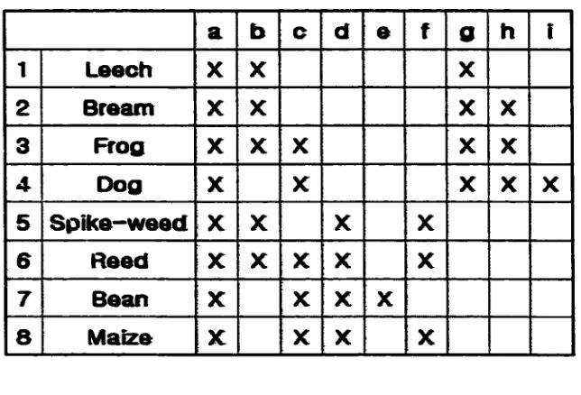
2.6.2.3. Formal Context
From the above two sets (object and attribute sets), the Formal Context can be derived.
Usually, Formal Context is represented by a cross table as given in Figure 2. The first
row represents all elements of the attribute set whereas the first column represents all
elements o f the object set. For convenience, numbers ( 1,2 ,..., 9) and alphabets (a, b , ...,
0 are used to represent all elements of object set and attribute set respectively.
a b c d e f 0 h i
1 L eech X X X
2 B ream X X X X
3 F rog X X X X X
4 D og X X X X X
5 S p ik e -w e e d X X X X
6 R eed X X X X X
7 B ean X X X X
8 M aize x: X X X
Figure 2. Cross Table.
“X” in a cell o f the cross table implies that the particular object posses that
attribute. For example, Leech has marked attributes a, b, and g meaning that leech needs
water to live, lives in water, and has two seed leaves.
2.6.2.4. Format Concept
A Formal Concept is a pair comprising o f an object set and an attribute set. From the
cross table in Figure 2, followings the definition o f a Formal Concept, 19 Formal
Concepts are derived. Each o f these Formal Concepts according to the above definition is
given a s :
({133,4,5,6,7,8,}, {a})
({1,2,3,5,6}, {a,b})
({3,4,6,7,8}, {a,c})
({IA3,4,1, {a,g})
({5,6,7,81, {a,d})
({IA 31, {a,b,g})
({2,3,41, {a,gM)
({5,6,81, {a,d,f})
({6,7,81, {a,c,d})
({231, {a,b,gdi})
({3,4}, {a,c,gdt})
({3,6}, {a,b,c})
({5,6}, {a,b,<Lf})
({6,8}, {a,c,d^})
18 Concept I :
Concept 2 :
Concept 3
Concept 4 :
Concept 5 :
Concept 6 :
Concept 7 :
Concept 8
Concept 9 :
Concept 10 :
Concept 11 :
Concept 12 :
Concept 13 :
Concept 14 :
• Concept 15 :
• Concept 16 :
• Concept 17 :
• Concept 18 :
• Concept 19 :
({3}, {a,b,c,g,h})
({4}, {a,c,gdU})
({6}, {a,b,c,<tf})
({7K {a,c,d,e})
({}, {a,b,c,d,e,f,g,h,i})
The first set consists o f numbers representing an object set in which each number
represents each object described in Section 2.6.2.1. The second set consists o f alphabets
representing an attribute set such that alphabet represents an attribute in Section 2.6.2.2.
For example, the [concept 12] contains “3” and “6” as elements of object set, and “a”,
“b”, and “c” as elements o f attribute set and represents that “Frog and Reed need water to
live, live in water and live on land”.
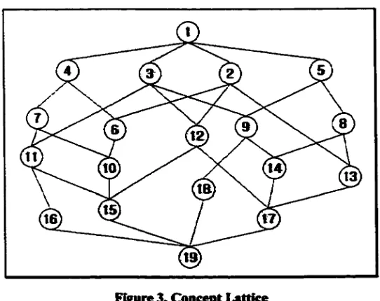
2 .6 2 5 . Concept Lattice
Figure 3, Concept Lattice
Concept Lattice looks like a hierarchical tree structure. In Concept Lattice, all Formal
Concepts are linked to each other by the definition of the relation(<). From above
Formal Concept in this figure, a Concept Lattice structure as shown in Figure 3 is
obtained. A circle represents a concept and the number in a concept represents concept
numbers.
20
3. Thesis Approach to Image Retrieval System
In this thesis, two methodologies ace introduced in order to add images into a lattice
structure. The first methodology is a bit set structure representing an attribute set
structure based on the 1-D string o f the 2-D string. The attribute set is one of sets in
concept nodes and represents real object in the world. The second is an Addition Method
for rebuilding a lattice structure. This addition method rebuilds only a part o f a lattice
structure when an image is added into the lattice structure.
3.1. Attribute Set Structure
Let O be a finite set o f symbols representing some real world objects given as :
0 = {a, b, c, ...1
where a, b, c , are the real objects.
Like l-D string as mentioned in Chapter 2, a representation o f an attribute set forms
X1X2 x„, where Xi is an object in real world. The difference between attribute set and
1-D string is that spatial information is provided in l-D string but is not provided in an
attribute set. For example, (A < B < C : D) was described as the representation o f l-D
string o f u in Section 2.5. This l-D string contains both object (A, B, C, and D) and
spatial (< and :) information. However, (ABCD) is the representation o f attribute set
containing only object information. Then a bit set structure is used to represent each
attribute set.
3.1.1. Bit Set Structure
To represent image attributes, the use o f bit set structure, also known as bit vector, is
proposed. A bit set structure is composed o f a fixed number o f bits in which each bit
represents a real object appearing in an image. If the universal set U contains N items, an
N-bit vector can represent any subset S o f U. Bit ki* will be I if i ^ S , otherwise bit T is
set to 0. Therefore, it is initialized to ‘O’ to indicate an empty set. This scheme requires
use o f only 1 bit per element. Therefore, an advanced knowledge o f the size o f universe
is required. However, it is a very space efficient even for large values o f U. Element
insertion or deletion simply requires flipping the appropriate bit. Intersection can be
performed simply by performing the AND operation.
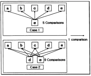
Use o f bit set structure allows for efficiently finding one or more attributes. For
example, suppose there is five attributes (a, b, c, d, e) as elements o f an attribute set
without using a bit set structure, and an “e” in the attribute set is considered as a query
attribute. In worse case, five comparisons are needed to find “e”. The query character “e”
is compared with “a” to “e” until “e” in the attribute set is found. Therefore, five
comparisons are needed as shown in the Figure 4-Case I. If the query attribute set
contains “d” and “e” then nine comparisons are needed in worst case. First, “d” is
compared with “a”, “b”, “c”, “e”, and “d” in worst case then five comparisons are needed
to find “d” in the attribute set. Second, “e” is compared with “a”, “b”, “c” and “e” except
for “d ” in worst case then four comparisons are needed to find “e” in the attribute set
shown in Figure 4-Case2. However, if the bit set structure is used, only two comparisons
are needed in both cases because “AND” and “EQUALITY” operations are used.
22
5 Comparisons
Case 1
1 comparison
9 Comparisons
Case 2
Figure 4. Finding attributes in general
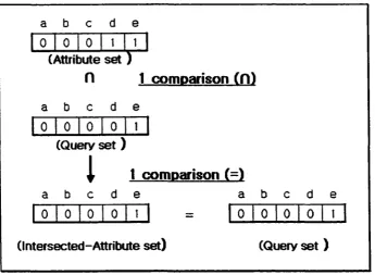
By using AND operation (intersection), an intersected-attribute set is obtained then
by using EQUALITY operation, the intersected-attribute set is compared with the query
attribute set. Similarity o f two attribute sets implies that an attribute set satisfying the
query attribute set is found. Formally, the above explanation is described as follow :
ag ~ a‘
if aq = ai then ag is the attribute set if aq * a, then ag is not
, where
% is a given attribute set
aq is a query attribute set
ai is a intersected attribute set.
For example, in Figure 5, the first comparison occurs when an attribute set is
intersected with the query set by using AND operation. The second comparison occurs
when the equality of the intersected attribute set and query set is checked. Therefore, a
procedure that finds an attribute set satisfying a query attribute set needs two
comparisons if a bit set structure is used.
a b c d
e
0 o1
0 t 1(Attribute set )
H 1
comoarison
( f l )a b c d
e
0 0 0 0 1
(Query s e t)
a b
1
c d
t comDarison (=)
e
a
b c d e0 0 0 0 t = 0 0 0 0 I
(Intersected-Attribute set)
(Query set )
Figure 5. Finding attributes with an bit set structure
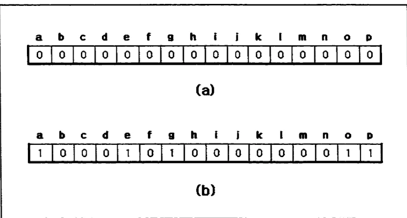
3.1.2. Example of a Bit Set Structure
In order to demonstrate use o f a bit set structure, consider the image shown in Figure 6
with attributes Bridge (a), Parking Lot (e), Car (g), Streetlight (o), and Tree (p). Suppose
that the size o f bit set structure is 16 bits. It is capable o f representing 16 different
attributes marked a through p.
24
Objects in this image:
Bridge(a), Parking Lot(e), Car(g)
Streetlight(o), Tree(p)
Figure 6. An example image Tor Bit Set Structure
From the image in Figure 6, an attribute set {a, e, g, o, p} is obtained. Initially all
o f the bits o f bit set structure are set to “0” as shown in Figure 7-a. With two known facts
(attribute set and bit set structure), a bit set structure, which represents the image in
Figure 6 such that we assign “ I” to “a”, “e”, “g”, “o”, and “p” is obtained. The resultant
bit set structure is shown in Figure 7-b.
a
b
c d e f 9 h i 1 k 1 m n o pD
l 0 0 0 0 0 0 0 0 0 0 0 0 0 0 0(a)
a
b
c d e f g h I 1 k 1 m n o P1
' 0 0 0 1 0 1 0 0 0 0 0 0 0 1 1(b)
Figure 7. Bit set structure representing image attributes o f Figure 6
3.2. Building a Lattice Structure
Until recently, because o f time complexity, only few systems dealing with relatively
small amount o f data have applied FCA. The worst case time complexity for building a
lattice structure in general is 0(n"). A fast algorithm for building lattice is introduced at
Harvard University in which the time complexity is said to be 0(n*) [27]. However, the
time complexity is still not good enough for applications dealing with large amount o f
data. To build a lattice structure, all o f the objects are collected, all concepts are extracted,
and then the concepts are linked. However, for any addition o f a new object, whole
lattice structure needs to be rebuilt causing expensive mathematical and computing
operation, thus limiting the use o f FCA in different potential applications [27].
In this section, an addition method is introduced to build a lattice structure. This
addition method is useful only when a lattice structure is already existed since it simply
rebuilds only a part o f the lattice structure rather than the entire lattice structure. The time
complexity o f this method is 0(2"), where n is the number o f attributes.
Lemma 1.: The total number o f concepts in a lattice structure is at most 2"-2.
Proof:
Let n be the number o f attributes and Sn be the number o f concepts in a lattice
structure (excluding the top and the bottom nodes).
By inductive method
if n = I then 5, = 0
ifn = 2then 5 ,= ,C l = 2
if n = 3 then S3=3CI+ JC2 = 3 + 3 = 6
26
For an arbitrary n, it is necessary to find the number o f concepts.
Ifn = kthen S*=*Ct _,+t Ct _2 +....+t Cl = £ * C r t
n
Now, by binomial expansion ({a+b)n = ] £ nCra n~rbr ) and by substitution a = I
r-Q
and b = I, we obtain:
2 -.C o + .C , +*„+nClt_l+ /lC#r, where nCx + ..a-nCn_x nCr
r-= 1
r = l
Therefore, the total number o f concepts S n = 2* - 2.
Corollary 1.1.: Possible concepts1 are obtained among 2n- 2 concepts in worst case.
Possible concepts are obtained by comparing an attribute set with attribute sets in
a lattice structure and in worst case, 2"-2 concepts are in the lattice structure as
described in Lemma I. Therefore, possible concepts are obtained by checking
among 2n- 2 concepts in the lattice structure. Steps for how to get and how to use
possible concepts are described in Section 3.2.1.
Lemma 2.: The worst case time complexity o f addition method is 0(2"). Proof:
As described in Lemma I., 2"-2 concepts exist in a lattice structure in worst case
and possible concepts are obtained among 2"—2 concepts as described in Corollary
1 Possible Concept: a possible concept is a concept, which could be one o f concepts o f a lattice structure. If the lattice structure already has a concept, which has same attribute set as that of a possible concept, the possible concept does not need to be added into the lattice structure. If not, the possible concept is added. Therefore, we call it as a possible concept.
l.L An addition method described in 3.2.1, extracts these possible concepts. In
other words, the addition method checks 2"-2 concepts except for the top and the
bottom nodes in the lattice structure and extracts all possible concepts. Therefore,
2"-2 comparisons are needed i.e., the worst time complexity for addition method
is 0(2 n-2) = 0(2”).
3.2.1. Addition Method
In the proposed addition method to add new concept in an existing lattice structure, first,
all possible concepts related to the new object are found then the superconcepts and
subconcepts o f all or some of possible concepts are tried to be find. Finally, all or some
o f possible concepts are linked to them (superconcept and subconcept) by the
hierarchical order of FCA. As explained in the annotation o f Possible Concept, if an
attribute set o f possible concept is the same as one o f attribute sets in a lattice structure,
the attribute set o f possible concept is not added into a lattice structure. Therefore, in
some cases, the addition method deals with only some o f possible concepts rather than
all o f them. In this section, the addition method is introduced with six steps.
Step I
hi this step, the addition method finds possible new concepts by comparing the attribute
set o f new object with the attribute sets o f concepts in a lattice structure. The size of
possible new concepts obtained in this step determines the efficiency o f addition method.
The more possible new concepts created, the more time taken. However, in this addition
method, all concepts in a lattice structure are examined on the first examination as shown
28
in Lemma 2. As a result, redundant attribute sets2 or empty attribute sets3 o f possible
new concepts are created in some cases. Therefore, the second examination is needed to
remove some o f possible concepts whose attribute sets are redundant attribute sets or
empty attribute sets. Formally, let at be an attribute set o f a possible new concept, ar
be a redundant attribute set, ae be an empty attribute set, where I < i < 2n-2. • If K | = 0 then a t = ar .
• if |a |. * 0 and a, s aj, where I ^ j < i and t < j ^ 2n-2 then at = a r .
Consequently, a possible new concept whose attribute set is considered as ar or a , is removed in this step.
Step 2
After possible new concepts are computed in Step I, it is necessary to find superconcepts
o f those concepts. This step employs the depth first and top-down search methodologies.
From the top node, subconcepts o f current node are checked with conditions described
below. The lattice structure is a hierarchical tree structure requiring checking o f the same
concept more than once. Therefore, by using the characteristic o f the depth first search,
this step avoids checking a concept, which is already examined.
In order to be a superconcept for possible concepts, each concept in a lattice
structure must satisfy the following simple conditions, which are based on the order
relation ( ^ ) as described in Section 2.6.1.
2 Redundant Attribute Set is an attribute set whose elements are same as one of attribute sets in a lattice structure. In other words, the redundant attribute set is already existed in a lattice structure.
3 Empty Attribute Set is an attribute set whose size is 0. The attribute set is obtained when the intersections of new object's attribute set and attribute sets in the lattice structure are empty set.
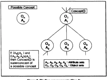
Condition I : Let C l be a concept in a lattice structure, at be an attribute set o f
C l, at be an attribute set o f subconcept o f C l and a„ be an attribute set of possible
concept. If (at^a„) and (Vi, at<r a„) then C l is a superconcept o f the possible
concept as shown in Figure 8.
Condition 2 : if two attribute sets are the same and the number o f elements o f a
object set in a possible concept is greater than the number of elements o f a object
set in a concept o f lattice structure, then an object set o f a concept in lattice is
replaced with the object set o f a possible concept.
Possible Concept
Concept®
If CA^A,,) and (CA2.A3.A4)cAn). then Concept® is superconcept of a possible concept
A|» Aj. A* A*. A, : Attribute sets Ot. 02.0 3 ,0«. On : Obiect sets
Figure 8. Finding superconcepts (Step 2)
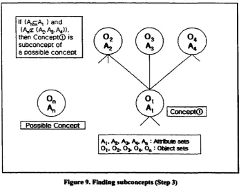
Step 3
In Step 2, superconcepts o f possible concept are found. In this step, it is necessary to find
30
subconcepts o f possible concept. This step is based on the depth first and bottom-up
search methodologies. To find subconcepts, it is not necessary to check the concepts
since these are already checked in Step 2. Therefore, in this step, the bottom-up search is
used instead o f a top-down search. The condition o f Step 3 is similar to the Condition I
o f Step 2 and is given a s :
Condition I : Let C l be a concept in a lattice structure, at be an attribute set o f
C l, at be an attribute set o f superconcept o f C l and an be an attribute set o f
possible concept. If (an^aO and (Vi, a„ cz aO then Cl is a subconcept o f the
possible concept as shown in Figure 9.
If (A^A, ) and (A„<r (A0.A3.A4)). then Concept© is subconcept of a possible concept
Concept©
Possible Concept
At, A^ Ag : Attribute sets Ot, 02.0 3 , O4, 0„ r Object sets
Figure 9. Finding subconcepts (Step 3)
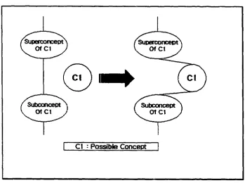
Step 4
.
In this step, it is necessary to link a possible concept to its superconcepts and
subconcepts, as found in Step 2 and Step 3. However, in this process, it is also necessary
to find if a superconcept and a subconcept o f a possible concept are already linked. If it is
the case, it is necessary to disconnect them and connect them again to a possible concept
as shown in Figure 10.
I Ct : Possible Concept
Figure 10. Linking superconcepts and subconcepts to a possible concept
Until now, only a single possible concept as created in Step 1 has been dealt
However if more than two possible concepts are created, it is necessary to repeat Step 2 -
Step 4 for remaining possible concepts. After addition o f all possible concepts, it is
essential to add the new object as described below m Step S and Step 6.
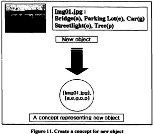
Step 5
This step is similar to Step 2 and Step 3. The difference hence is that new object rather
than a possible concept is added. However, before carrying out this step, it is essential to
32
create a concept for the new object as shown in Figure 11 followed by Step 5, which is
the same as Step 2 and Step 3.
TmgQ1.jpg :
Bridgefa), Parking Lot(e), Car(g) Streetlight(o), Tree(p)
New object
*
{Img01.jpg}, {a.e.g.o.p}
A concept representing new object
Figure 11. Create a concept for new object
Step 6
In this step it is essential to link the concept o f new object to the superconcepts and
subconcepts as found in Step 5. This step is the same as Step 4.
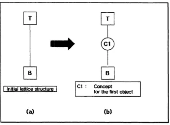
3.2.2. Example of Building a Lattice Structure
Initially, there is an empty lattice containing only [T] and [B] nodes, which represent the
TOP and the BOTTOM respectively (Figure 12-a). The addition o f the first object into a
lattice structure does not require Step I to Step 4 because no concepts are presented in
the initial lattice structure. During the processing, a concept for the new object is created
as shown in Figure 11 and then the concept is added to the lattice structure connecting it
to [T] and [B]. The nodes [T] and [B] become a superconcept and a subconcept
respectively o f the first object as shown in Figure 12-b.
B
Initial lattice structure
@
B
Cl : Concept
for the first object
(a)
(b )Figure 12. (a) Initial lattice structures (b) after adding first object
Suppose two objects (Figure 13-a) are already added into an initial lattice structure
resulting in a lattice structure with three concepts as shown in Figure 13-b. Now the third
image as shown in Figure 14 is to be added. According to Step 1, the attribute set of the
third object is intersected with the 3 attribute sets o f the existing concepts (Cl , C2, C3) in
the lattice structure and three possible concepts (PCI, PC2, PC3) are obtained as shown
in Figure IS.
34
ImgOl.ing
Bridga, Parking Lot, C ar Streetlight, Tree_______
Iwg02.jpg
Building, Lawn, Streetfight Tree
GO
C2
Ct
C3
GO
Figure 13. (a) Objects and (b) their addition into the lattice structure
Building, Car, Hydrant, Lawn, Tree
Figure 14. Addition o f 3rd image and objects
After obtaining possible concepts, it is essential to find a superconcept and a
subconcept for PCI concept. In this cas, [Tj and C l are the superconcept and the
subconcept repectively and need to be linked to PCI (Figure 16-a). For PC2, PCI is a
superconcept and C2 is a subconcept. After linking these, the resulting lattice structure is
shown in Figure 16-b. For PC3, PCI is a superconcept and C3 is a subconcept. After
linking these, the lattice structure is obtained as shown in Figure 16-c.
{tmg3} ^ NCI (new object)
Possible concents
, ngl. 2. 3fS| PCt
(= NCt
n ci)
img2.3} PC2 (= NCt n C2)
PC3
(= NCt n C3)
C l
jmgl. Img2] . Co. p} .
C3 C2
Clmgt) N e. g, o. a
Figure IS. Possible concepts
So far, only three possible concepts, which are obtained by intersecting new object
with existing concepts in a lattice structure have been added. Now, it is essential to add a
new object. The steps are involved below:
• Find superconcepts : In this case, two superconcepts (PC2 and PC3) are obtained.
• Find subconcept: which is the Bottom node [B].
• Connect the nodes.
The resulting lattice structure with seven concepts after addition o f three objects is
shown in Figure 17. With this addition method, new objects have been added by
rebuilding only a part o f the lattice structure rather than rebuilding the entire lattice
structure.
36
C2 C3
( a )
’Cl ’Ct
Ct
C2 C3 C2 C3
(b) ( c )
Figure 16. Addition of three possible concepts
’C l
C l
C2 C3
3.3. Image Retrieval
To retrieve images corresponding to a query image, it is necessary to find a concept. This
is because a concept in a lattice structure consists o f an object set and an attribute set.
The object set consists o f images and the attribute set consists o f real objects. Therefore,
if a concept is found by comparing its attribute set with query attribute set, images,
which satisfy with the given criteria, are retrieved Grom its object set.
In order to search for images corresponding to a query image, we start with any
superconcept o f the Bottom node [B] then examine attribute sets of concepts in a lattice
structure to find the concept, [f the attribute set obtained after intersecting a query
attribute set with a superconcept o f [B] is the same as the query attribute set, then we
keep searching by comparing a superconcept of the superconcept of [B] with the query
set until the condition below is satisfied. For example, suppose ai is an attribute set o f a
superconcept o f [B], aq is an attribute set o f query image, and at is an attribute set after
intersecting aq with at. In other words, aq fl a t = at. If at is the same as aq (at = a,)
then we keep checking superconcepts o f the concept, whose attribute set is at until the
following condition is satisfied:
Condition : If the intersected attribute set obtained by interesting a query attribute
set with a concept® attribute set in a lattice structure is a subset o f the concept®,
and the intersected attribute set is not a subset o f superconcepts o f the concept®,
then the concept® is the concept satisfying the user query. For example, suppose
a concept® has 3 superconcepts and at is the attribute set o f the concept® and
a,t, a^, a»3 are the attribute sets o f the three superconcepts o f concept® and a , is
38
the attribute set of query image. To satisfy the above condition, the following
conditions must hold:
• at
n
aq = aq• a,i D a,, ^ a,
• a*2 H a , aq
• 3s3 ^ 3q
Formally, the condition is described as follow:
C, be a concept from Cp in a lattice structure
CM be one o f superconcept o f C, C, be a subconcept o f C,
a, be an attribute set o f C,
be an attribute set o f C„
a« be an attribute set o f query
• if at r\a q * aq then move back to Cp
• if a i r \a q =aq and 3i,a sin a q =aq then move to C„ and keep searching • if at r \a q =aq and n a q * a q then C, is the concept, which is
satisfied with given user query.
3.3.1. Image Retrieval Examples
Suppose a query set consists o f attributes {b, I, o, p} and for convenience, only a part o f
the lattice structure is taken as shown in Figure 18. Figure 18 shows part o f the complete
lattice structure given in Figure 3.
0 5
C7
Figure 18. Section o f complete lattice o f Figure 3.
• At [B], check the superconcepts o f [B].
Concent C 7 :
{ b ,l , 0 ,p } query Pi { b , g j , l , p ^ Concept C7 = { b ,l,p } intersected set
{b,I,o,p}quety * {b,l,p}intersected set
Go back to [B], and check the concept Ct I.
Concent Ct I :
{ b , I , 0 , p } quetyf) { b , k , I ^ n , 0 , p } Concept C l { b » l,0 ,p } intersected set
{b,I,o,p} quety {b,l,o,p}intersected set
Then go to the concept C l 1.
• At Concept C t I, check the superconcepts o f C l 1.
40
Concept C3 :
{ b ( l,0 ,P } queryfl { b ,I ,0 ,p } Concept C l { b ,I ,0 , p } intersected set
{ b ,I ,0 , p } q u e ry ~ { b ,I,0 ,p } intersected set
Then go to the concept C3.
• At Concept C3, check the superconcepts o f C3.
Concept C 6 :
{ b ,l , 0 ,p } query f l {b,I,p}Concept C7 { b ,I,p } intersected set
{ b , 1,0,p } qUery ^ { b ,l,p }intersected set
Go back to C3, and no more superconcepts o f C3.
* At C3, there are no more superconcepts to be checked, and a query set is a subset
o f Concept C3, then the Concept C3 is the concept, which satisfies with the
given query. After finding C3, the images (Img2, and Img5) can be retrieved by
checking the object set o f the Concept C3.
3.4. Search and Retrieval Scheme
Retrieval o f images in this case is a combination o f the depth first and bottom-up search.
This section describes the significance o f the use o f the bottom-up search in this scheme.
Three cases are introduced to demonstrate its use and importance.
Why bottom-up search