Feasibility Study of SAR Processing using
High Level Synthesis
Milan J. Domadiya
1, B.Saravana Kumar
2, Prof.Swetal Pandya
31
M.Tech student, Dept. of EC, BHGET, Rajkot-360001, Gujarat, India
2Scientist/Engineer, Dept. of MSDPD/MSDG/MRSA,SAC (ISRO), Ahmedabad-380015, Gujarat, India 3Assistant Professor, Dept. of EC, BHGET, Rajkot-360001, Gujarat, India
ABSTRACT: This paper presents literature survey and feasibility study carried out for implementation of SAR processing algorithm on multiple FPGA’s using High Level Synthesis (HLS) tools. Direct implementation of SAR processing algorithm using manual HDL coding takes longer development time, complex design and code. This problem can be overcome by using High Level Synthesis (HLS). By using HLS, generic RTL can be generated directly from C or C++ source code which helps in rapid prototyping of the design
KEYWORDS: High Level Synthesis, FPGA, Vivado HLS, Synthesis Aperture Radar, Register Transfer Level (RTL)
System on Chip (SoC).
I. INTRODUCTION
Idea of HLS and its implementation has been changed through years. It has evolved as a technique to enhance the production of large integrated circuit and more complicated digital system. Presently HLS can be considered as three main tasks: System description, scheduling, resource allocation and binding. System description includes specifying the functionality of the eventual hardware, scheduling assigns the operations and their execution in time, and resource allocation and binding is used to define the implemented hardware [1].
High-level synthesis takes a complete behavioural of C/C++ description of a system along with a series of directives that describe the architectural constraints, and automatically generates a HDL design description [2].Digital signal processing applications lead to the implementation of more and more complex algorithms and systems. To handle this increase in complexity and the design methodologies based on HLS can be used. High-level synthesis is analogous to software compilation transposed to the hardware domain. From an algorithmic behaviour of the specification, HLS Tools automate the design process and generate an RTL architecture taking into account user-specified constraints. HLS based design flow allow the design time to be reduced compared to traditional design methodology based on handcraft RTL architecture[3]. Martin and Smith describe the evolution of HLS tools in terms of user experience and commercial viability [4].
II. HIGH LEVEL SYNTHESIS TOOLS
There are a number of HLS tools like: Xilinx AccelDSP, Agility compiler, Autopilot, BlueSpec, Catapult C, Compaan, C-to-Silicon, ROCCC, Synphony C Compiler and this paper mainly focus on Vivado HLS Tool [4].
Vivado HLS is the Xilinx HLS engine, accepting descriptions in C, C++ or SystemC and generating VHDL, Verilog
and SystemC RTL descriptions. These descriptions can be packaged as IP blocks and imported directly into the Vivado Design Suite for series 7 Xilinx device implementation [5].
The functionality inside Vivado HLS enables the following design flow:
Compile, execute (simulate) and debug the C algorithm.
Comprehensive reporting and analysis capabilities.
Automated verification of the RTL implementation.
Package the RTL implementation into a selection of IP formats.
Tool procedures
Although the approaches use different techniques, they tend to converge to basic ideas of high levelsynthesis. These include scheduling problems, allocation of resources and the binding of designwith the hardware modules. The procedure is automated but the user can guide the tool with theinput of constraints regarding the design.
Loop control or iteration scheduling
Loops and tasks can be handled in different ways providing the user with the ability to expose and manipulate parallelism appropriate for that design. Unrolling can be used to create additionalcopies of the hardware to implement the loop or task. Pipelining can be used to increase thethroughput by initiating the next loop iteration or task before the current iteration is completed.
Schedule directives
Almost all tools allow the possibility to interact with scheduling, mainly through directives thatcontrol latency, cycle time, throughput and timing of whole or part of the design.
Resource allocation and binding
The tools provide means to allow the user to interact with the resource binding. Resource manipulationcan include specific allocation of design input-output, specific memory architectures and useof IP accelerating libraries.
Verification and quality of results
Earlier tools suffered from variable quality of results while producing difficult to validate hardware.Verification has become an essential part of modern HLS tools and it might even be their mostcompelling advantage over more traditional design flows. Verification comprises two stages. The first verifies the algorithmic correctness of the inputcode and the second validates the correct transformation of the design description to RTL. The firststep is usually done through simulation while the second is accomplished either by simulationbasedmethods. For simulating and verifying the output most of the tools provide an automatedprocess to allow the test benches used for the input code simulation of the input code to be re-usedto verify the output RTL.
III. DESIGN PROCEDURE FOR VIVADO TOOL
This design procedure [6] for starting a new Vivado HLS project can be split up in to key steps:
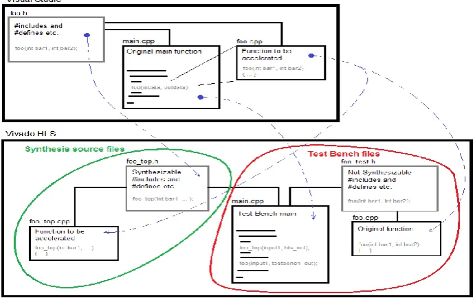
1. Write a C/C++ program (in Visual Studio). Put all algorithm code in a single function to easier separate the overhead code from the actual algorithm to be accelerated. Use .h file forincludes and function declaration.
2. In Vivado HLS create two files, one with the function from step 1, and one with the main () from step 1. Any other utility files or similar can also beput in as Test Bench files, since they will only be used during C Simulation.
3. Create a new Source file. Put only the function to be accelerated from step 1 here. Vivado HLS will try synthesize all files listed as source in this project.
6. Create a second .h file, this time in the Test Bench. This header file will only be included in the Test Bench source files, and thus can contain any synthesizable functions/includes needed for validation during C simulation.
7. In the Test Bench main (), include both .h files from step 5 and 6. Call both the Top Function from step 4, and the test bench function from step 2 and use the exact same input data.
8. Add some code that compares the output data from both functions and exits with 0 for success, and 1 for failure.
9. Test run the Test Bench. It should now run the two functions with same input data and compare their output which should be identical.
Figure 2: Initial process for starting a Vivado HLS project
Vivado HLS can also run a C/RTL Co-simulation using the synthesized RTL with the test bench [5]. With a finished and working test bench, and synthesized RTL, Co-Simulation is just a click away. This will test the synthesized RTL by first using the test bench to generate input for the RTL, and then run it through the RTL. Finally the results of the RTL simulation is used in a new run-through of the C/C++ test bench. If successful run this test bench then waveform report generate for more detailed study.
IV.SYNTHETIC APERTURE RADAR
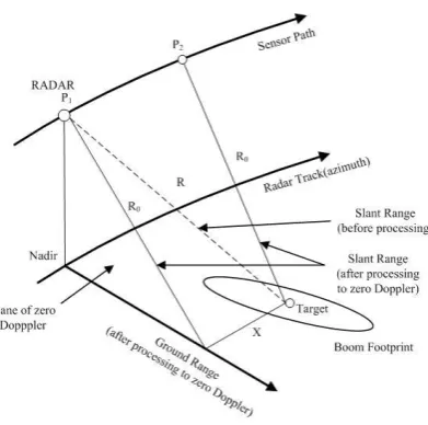
Figure 3: SAR geometry
In range the length of the received data is fixed which only depends on device and in azimuth the data length is relative aperture size and whole raw data size is proportional to the observation time. A number of different SAR data processing algorithms have been developed so far [9, 10]. The range-Doppler algorithm (RDA) is one of the most widely used [10, 11].
Bandwidth
The bandwidth of the transmitted chirp pulse directly affects the range resolution of the output image. With increase in bandwidth the VALUE OF range resolution of the output image decreases, resulting in decreased pixel spacing and hence a better image quality. This relationship is shown in below
Range resolution = c /2*B.W.
Sampling Rate
A higher sampling frequency will yield a better output image. This will result in a increased mass memory size. The sampling frequency should be selected to effectively balance the image quality and the mass memory size [12].
Transmitted Pulse Duration
With an increase in transmitted pulse duration of RADAR, the received power also increases. This yields a better image quality as the reflectors from the end of swath also give echoes with higher amplitudes and objects of lower backscattering coefficients also become visible in the output image.
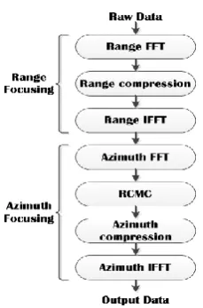
V. SARPROCESSING IN THE RANGE-DOPPLER DOMAIN
Figure 4:Procedure of range-Doppler algorithm.
VI.CONCLUSION AND FUTURE WORK
After the survey of this paper we conclude that the latest generation of FPGA HLS tools has made significant progress in providing wide language coverage, robust compilation technology, platform-based modelling, and domain-specific system-level integration and as a result they can quickly provide highly competitive quality of results, in many cases comparable or better than manual RTL designs. This paper has presented application of the Xilinx Vivado HLS tool for C/C++-based design capture, simulation and synthesis to HDL format, and further to FPGA hardware implementation. The paper demonstrates the practical steps in Vivado using HLS and the resulting hardware implementation.
REFERENCES
[1] Spyridon Georgakakisa and John Evansb,"Overview of high level synthesis tools", iop publishing for sissa (2010).
[2] Declan O’Loughlin, Aedan Coffey, Frank Callaly, Darren Lyons, Fearghal Morgan," Xilinx Vivado High Level Synthesis: Case studies",ISSC 2014 / CIICT 2014, Limerick, June 26-27.
[3] Emmanuel Casseau and Bertrand Le Gal,"High-Level Synthesis for the Design of FPGA-based Signal Processing Systems".
[4] G. Martin and G. Smith, "High-Level Synthesis: Past,Present, and Future," IEEE Design & Test of Computers, vol. 26, no. 4, pp. 18-25, Aug. 2009.
[5] “Vivado Design Suite User Guide: High-Level Synthesis”, available from http://www.xilinx.com. [6] “Vivado Design Suite Tutorial”, UG871 (v 2014.1) May 6, 2014.
[7] Naeim Dastgir, “Processing SAR data using Range Doppler and Chirp Scaling Algorithms”, Master’s of Science Thesis in Geodesy Report No.3096 TRITA-GIT EX 07-005.
[8] Carmine Clemente, Maurizio di Bisceglie, Michele Di Santo, NadiaRanaldo, Marcello Spinelli, “Processing of Synthetic Aperture Radar Data with GPGPU,” IEEE Workshop on Signal Processing Systems, SiPS: Design and Implementation, p 309-314, 2009.
[9] C. Oliver and S. Quegan, Understanding Synthetic Aperture Radar Images. Norwood, MA: Artech House, 1999.
[10] I. G. Cumming and F. H. Wong, Digital Processing of Synthetic Aperture Radar Data: Algorithms and Implementation”. Norwood, MA: ArtechHouse, 2005.
[11] O.O. Bezvesilniy, I.M. Gorovyi, V.V. Vynogradov and D.M. Vavriv, “Range-Doppler algorithm with extended number of looks”, in Proc. Of 3rd Int. Microwaves, Radar and Remote Sensing Symp. MRRS 2011 (Kyiv, Ukraine), pp. 203-206, 2011.
[12] Mehrdad Soumekh “Synthetic Aperture RADAR Signal Processing”, 1999.
[13] J. C. Curlander, R. N. McDonough, Synthetic Aperture Radar: Systems and Signal Processing, John Wiley and Sons, 1991.