KRIPAKARAN, PRAKASH. GA-Based Decision Support for Optimizing the
Response of Secondary Systems. (Under the direction of Dr. Abhinav Gupta).
The objective of this research is to develop a Decision Support System (DSS) for
seis-mic design and performance evaluation of piping supports. The current practice of
design-ing pipdesign-ing support locations is primarily heuristic, relydesign-ing heavily on professional
expe-rience. In this thesis, approaches to optimize support locations using Genetic Algorithms
(GAs), a heuristic optimization technique, are discussed. These approaches have been
im-plemented in a DSS using Vitri, a generic, distributed framework designed to support the
development of DSSs, which reduces the computational requirements by combining the
processing power of a network of workstations.
Previous attempts to solve the problem of pipe support optimization modeled supports
as flexible springs, which have a stiffness depending on the support capacity, resulting in
the use of an integer representation in the GA. In this thesis, a new approach where supports
are modeled as rigid springs is presented. This permits the use of a binary representation
in the GAs. Also, earlier attempts had solved the problem by minimizing the number of
supports, which does not always indicate if cost is minimized. In this thesis, capital cost and
lifetime cost are studied by examining the trade-off curve between the cost and the number
of supports. A crossover scheme aimed at generating cost optimal solutions of a specified
number of supports, which is required for generating trade-off curves, is proposed.
It has been observed that optimization results in solutions that may be practically
infea-sible because of unmodeled costs in the optimization model. In pipe support optimization,
such costs might be from the preference of certain locations over others because of
eas-ier support installation costs or the desire to locate the supports under lumped masses to
stabilize the pipe against local vibrations from equipment such as pumps and motors. The
role of Modeling to Generate Alternatives (MGA), a methodology based on optimization
by
Prakash Kripakaran
A thesis submitted to the Graduate Faculty of North Carolina State University
in partial fulfillment of the requirements for the Degree of
Master of Science
Department of Civil Engineering
Raleigh
2002
Approved By:
Dr. John W. Baugh, Jr. Dr. G. (Kumar) Mahinthakumar
Biography
Prakash Kripakaran, was born on June, 16, 1979, in Coimbatore, India, where he did most
of his schooling. His family moved to Madras in May 1993, where he went to high school.
He completed his Bachelor’s degree in Civil engineering at Indian Institute of Technology,
Madras. He joined the Masters program in Civil engineering in North Carolina State
Uni-versity in the fall of 2000 and has been working on this project from then on. He plans to
continue his research in this subject by pursuing a doctorate in Civil engineering at North
Acknowledgements
First of all, I would like to thank Dr. Abhinav Gupta for his guidance and encouragement
throughout the course for this research. I would also to like to thank the other members
of my committee, Dr. Baugh and Dr. Kumar, who along with my advisor Dr. Gupta,
made themselves available for a meeting almost every week, to discuss the progress of the
research. The discussion and the ideas generated during the meeting went a long way in
furthering this research.
I would also like to thank my friend, Sujay Kumar, who was a graduate student when
I joined the Masters program. He helped me learn Vitri, a framework he had developed
during his doctoral research at North Carolina State University, which I used all through
my research.
Lastly, this research would not have been possible without the moral support of my
Table of Contents
List of Figures vi
List of Tables viii
1 Introduction 1
1.1 General background . . . 1
1.2 Objectives . . . 3
1.3 Organization . . . 4
2 The Decision Support System 6 2.1 Design of DSS . . . 8
2.2 Vitri: A framework for engineering DSS . . . 9
3 Optimizing Seismic Response of Secondary Systems 12 3.1 Introduction . . . 12
3.2 Design of piping supports for seismic loads . . . 14
3.3 GA-based pipe support optimization . . . 17
3.4 Cost optimization . . . 22
3.4.1 Example piping system . . . 23
3.4.2 Capital cost optimization . . . 24
3.4.3 Lifetime cost optimization . . . 26
3.5 Modified objective function . . . 27
3.6 Modeling to Generate Alternatives (MGA) . . . 28
3.7 Application of MGA to pipe support optimization . . . 31
3.8 Application to real life piping system . . . 33
3.9 Summary and conclusions . . . 34
4 Other Results 57 4.1 Integer string representation . . . 57
4.3 Comparison of selection techniques . . . 58
4.4 Uniform crossover . . . 59
4.4.1 Lifetime cost optimization . . . 59
4.4.2 Modified fitness function . . . 60
4.4.3 MGA solutions . . . 61
4.5 Application to real life piping system . . . 61
5 Summary and Conclusions 71 5.1 Summary . . . 71
5.2 Conclusions . . . 73
5.3 Future work . . . 74
List of Figures
2.1 A sample graphical interface offered by Vitri . . . 11
3.1 Straight pipe with lumped masses . . . 41
3.2 Interfacing of PIPESTRESS and Vitri . . . 42
3.3 Illustration of the proposed crossover . . . 43
3.4 Results of multi-objective study for capital cost . . . 44
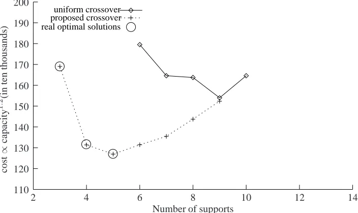
3.5 Results of multi-objective study for lifetime cost . . . 44
3.6 Optimal solutions for capital cost obtained using proposed crossover . . . . 45
3.7 Optimal solutions for lifetime cost obtained using proposed crossover . . . 46
3.8 Optimal solutions for lifetime cost obtained using proposed crossover . . . 47
3.9 θk/θkcfor supports of solutions in Figure 3.6 . . . 48
3.10 θk/θkcfor supports of solutions in Figure 3.7 . . . 48
3.11 Best fitness solutions using modified fitness function (Equation 3.14) for lifetime cost . . . 49
3.12 Multiple-objective optimization . . . 50
3.13 Decision space for LP example . . . 51
3.14 Flowchart showing incorporation of MGA in Vitri . . . 52
3.15 MGA solutions for lifetime cost withnreq = 5 . . . 53
3.16 MGA solutions for lifetime cost withnreq = 7 . . . 54
3.17 Real piping system (not to scale) . . . 55
3.18 Multi-objective study of lifetime cost for the real piping system . . . 56
4.1 Comparison of performance of various crossover schemes for lifetime cost . 63 4.2 Multi-objective study cumulative capacity as cost . . . 64
4.3 Comparison of selection schemes for capital cost using multiple seeds in GA 64 4.4 Comparison of selection schemes for lifetime cost using multiple seeds in GA . . . 65
4.6 Optimal capital cost solutions obtained using uniform crossover and binary
representation . . . 67
4.7 θk/θkcvalues for solutions given in Figure 4.5 . . . 68
4.8 θk/θkcvalues for solutions given in Figure 4.6 . . . 68
4.9 The best solution and the alternatives using Equation 4.2 . . . 69
List of Tables
3.1 Location of lumped masses along the pipe . . . 36
3.2 Cost and capacity of supports . . . 37
3.3 Properties of optimal capital cost solutions given in Figure 3.6 . . . 37
3.4 Anchor forces of optimal capital cost solutions given in Figure 3.6 . . . 38
3.5 Properties of optimal lifetime cost solutions given in Figures 3.7 and 3.8 . . 38
3.6 Anchor forces of optimal lifetime cost solutions given in Figures 3.7 and 3.8 39 3.7 Properties of optimal solutions obtained using Equation 3.14 . . . 39
3.8 Properties of MGA solutions fornreq = 5in Figure 3.15 . . . 39
3.9 Anchor forces of MGA solutions fornreq= 5in Figure 3.15 . . . 40
3.10 Properties of MGA solutions fornreq = 7in Figure 3.16 . . . 40
3.11 Anchor forces of MGA solutions fornreq= 7in Figure 3.16 . . . 40
4.1 Properties of solutions given in Figure 4.9 . . . 63
Chapter 1
Introduction
1.1
General background
Seismic design and qualification of secondary systems such as power plant piping, like
other complex decision problems, involves many tradeoffs among competing criteria. At all
stages in a power plant life-cycle, structural engineers are faced with formidable challenges
of complex decision-making. In the context of seismic design and performance evaluation,
these may relate to technical as well as practical feasibility, cost, and redundancy. Although
some of these challenges can be quantified and formally analyzed, others may call for
out-side opinions from experts or engineering judgment. Key features of the decision-making
process include identification of alternatives for solving the given problem. Then, whether
an alternative is satisfactory typically requires analysis by one or more computer models,
Research in structural optimization has included computation complexity studies [21],
traditional mathematical optimization [9], and modern heuristic optimization such as
ge-netic algorithms [20]. In practical applications, the use of mathematical optimization or
other formal search techniques may lead to “optimal” structural systems that are either
in-feasible or unnecessarily costly in the sense that they are not conducive to construction,
maintenance or serviceability. In this scenario, the optimization model produces a single
solution that is “best,” but only with respect to the objectives and constraints that appear in
the model: the unmodeled issues, such as downstream maintenance or outage costs, may
not have been factored into the search process. To produce a truly optimal solution, then,
would require that the judgment and expertise of an experienced designer somehow be
em-bedded in the model. These difficulties in modeling are a key limitation, not of optimization
techniques per se, but of the way in which they are routinely used.
Optimization for seismic support locations in piping systems is a highly complex and
iterative problem that is time and cost intensive. An extremely large number of
possibili-ties may exist, making enumeration impractical. The current practice of designing piping
support locations is primarily heuristic, relying heavily on professional experience.
Engi-neers use the knowledge learned from observed performances and past failures to arrive at
the most appropriate locations. In this paper, we explore the role of formal computational
approaches that support decision making in the seismic design and performance evaluation
of multiply-supported piping systems in critical industrial facilities such as nuclear power
1.2
Objectives
A primary system (such as building) is a structural system that receives seismic input
directly from the ground and filters it to the secondary system supported on it. Secondary
systems (such as equipment and piping) are supported on primary systems and do not
re-ceive seismic input directly from the ground. Seismic design for piping is dependent on the
seismic input it receives from the primary system (building). The piping receives this input
through the supports on which it is mounted. The seismic input transmitted through all the
supports may not be the same. It typically depends upon the floor elevations of the supports
in the primary system. Choosing appropriate support locations for the pipe optimizes the
overall cost of the supports and the response. The existence of numerous possibilities in
selecting the support locations and the absence of a strategy for choosing the support
loca-tions make it a complex-decision making problem. The primary objective of this study is
to explore the role of a Decision Support System (DSS) in seismic design and performance
evaluation of piping supports. This is realized using the following components:
• PIPESTRESS [8] - a finite element analysis software package, for evaluating the
seismic response of piping systems.
• Vitri [14] - a distributed, high performance computing framework designed to support
Decision Support Systems.
• Heuristic techniques such as Genetic Algorithms [10, 17] for pipe support
• MGA [4] - “Modeling to Generate Alternatives,” a methodology that utilizes
opti-mization, to generate alternatives that are similar in objective space, but very different
in decision space.
1.3
Organization
The thesis consists of five chapters. This chapter gives the introduction, objectives and
the overall organization. The second chapter discusses the concepts of the DSS to be
de-signed for the given problem. The DSS has been implemented on Vitri, a distributed
object-oriented framework developed for DSSs. The tools provided by Vitri and PIPESTRESS,
a commercial package for finite element analysis, are presented. The purpose of the DSS
and the approach taken to develop the DSS are described in detail.
The third chapter presents a GA-based optimization approach for choosing the seismic
support locations for power plant piping. It discusses improvements to various components
of the GA, such as, representation and crossover. It explains the optimization procedure
used for multi-objective study between cost (capital and lifetime cost) and the number
of supports and examines the trade-off curves obtained. It describes the MGA technique
used to generate alternatives to the optimal solutions obtained from the GA approach and
analyzes the generated results. Finally, the developed GA approach is applied to a real
life piping system and the results of the multi-objective study between lifetime cost and
objectives are repeated in chapter 3. The third chapter is essentially a manuscript to be
submitted to the ASCE Journal of Structural Engineering.
The fourth chapter consists of the results generated during the course of research but are
not given in the third chapter representing the manuscript. These include (a) comparison
of the performance of integer string representation with binary string representation, (b)
the alternatives generated by MGA technique while using uniform crossover, (c) results on
the selection techniques studied for lifetime cost optimization, and (e) intermediate results
obtained on application to real-life piping system. The last chapter gives the conclusions
Chapter 2
The Decision Support System
Decision support systems (DSSs) are formal approaches for computer assisted decision
making. A DSS is a computer system that initiates human involvement by helping
engi-neers to create alternatives, test their effects and interpret the generated results. A DSS
uses tools for analysis, optimization, etc., to assist the engineer in evaluating the
alterna-tives. Thus, engineers can select favorable alternatives for implementation.
Often, the decision maker does not have a full understanding of the problem and its
pa-rameters at the onset of the decision-making process. He strives to get a better
understand-ing of the problem through experimentation and trial-and-error. A decision makunderstand-ing process
can involve (a) tasks that require computer-intensive processing and (b) tasks that require
human judgment. A computer-based DSS [15, 18, 12] enhances the decision-making
pro-cess by providing the engineer with an easy-to-use problem solving environment that
is comprised of a human decision maker and a set of computational resources. DSSs allow
the engineer to monitor progress by presenting him with intermediate results for review. It
supports a collection of various analytical and computation techniques, schemes for
uncer-tainty propagation, and optimization tools.
The development of modern heuristic techniques such as genetic algorithms, combined
with high performance computing environments, have increased the scope of engineering
design problems that can be addressed by mathematical optimization. New approaches
for decision support where the intended role of optimization models is not to generate the
“best” solution, but rather to generate sets of good, alternative designs that provide
in-sight and creativity, have been developed. This approach has been applied for alternative
generation in the design of truss structures using integer-linear programming [1],
vehi-cle routing and scheduling using simulated annealing [2] and air quality management for
control-strategy optimization using genetic algorithms and simulated annealing [16], and
have been shown to greatly assist decision-making.
A distributed computing system can be used to improve the performance of
computa-tionally intensive DSS problems. For instance, computational resources can be assigned
jobs such as brute force calculations and information storage and retrieval. This permits
human decision makers to set their minds on activities such as consideration of abstract
is-sues, directing overall decision-making process, and providing feedback based on intuition
and professional judgment.
de-sign and serviceability requirements for compliance. These selections are then explored
with the help of the DSS. The decision maker uses his professional judgment for providing
useful feedback to the DSS in the form of changes made to the previous selections. In this
manner, the DSS employs an iterative process involving continuous modification to evolve
initially conceived potential solutions to a satisfactory solution. The following section
de-scribes the design of the DSS for seismic design and performance evaluation of secondary
systems.
2.1
Design of DSS
The DSS draws on the complementary strengths of the engineer and the computer in a
joint-cognitive system. Three components comprise the DSS,
• Finite element analyses are used for evaluating the seismic response of piping
sys-tems.
• Genetic algorithms are used as part of a formal procedure for generating alternative
solutions using a methodology referred to as “modeling to generate alternatives
-MGA” [4]. MGA uses optimization to generate a set of solutions that are similar in
objective space - “near optimal,” but very different in decision space - “as different
as possible.”
• The computational performance requirements of the DSS are addressed by using an
object-oriented framework, Vitri, includes basic support for distributed computing
and communication, and distributed GA implementations [3].
2.2
Vitri: A framework for engineering DSS
Vitri [14] is a generic, distributed, object-oriented framework for the development of
en-gineering DSSs. Vitri provides a high performance computing environment for distributed
computing that harnesses the resources of a network of computers to provide adequate
com-puting power to deal with the various problems. A lot of formal tools and concepts such
as optimization-based techniques have been developed, that help in searching for solutions
that optimize certain goals while satisfying specified constraints. The development of such
tools has helped in avoiding time-consuming enumeration of potential solutions for
prob-lems where good solutions are hard to find using a trial-and-error approach. Vitri provides a
number of formal computational approaches such as heuristic optimization techniques that
provide generic capabilities that are suitable for dealing with difficult, ill-behaved
prob-lems.
A decision maker is typically interested in details such as the trade-offs between cost
and a certain competing variable, the effect of uncertainties on solutions, etc. Formal tools
and concepts provided by Vitri can be used in an iterative decision making process to
assist with such what-if analyses. Moreover, tools for optimization can be used to generate
tool, Modeling to Generate Alternatives (MGA) [4], that is based on genetic algorithms, to
produce a small set of slightly sub-optimal solutions that are different in decision space.
Vitri also provides a number of graphical interfaces to evaluate and monitor the runtime
performance of the distributed system. Decision makers can use these graphical interfaces
to decide on whether to proceed with the exploration of an alternative. For instance,
con-vergence towards an optimal solution for a computationally intensive technique may be
aborted or re-routed by the decision maker based on the observations during the first few
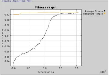
iterations. Vitri has a graphical display displaying the best fitness and the average fitness of
the population as the GA progresses. A screen capture to illustrate this is given in Figure
2.1.
Engineers often develop prototypes based on their ideas, and test them to gain a better
understanding. The framework in Vitri allows for rapid prototyping, which is desirable
for the DSS as designers can learn about the problem quickly. The object-oriented tools
and component-based modeling technologies of Vitri promote the development of modular
systems that are flexible and extensible. This also means that the tools in Vitri can be
reused for testing different prototypes and applications. Vitri not only facilitates an iterative
decision making process, but also helps the decision maker incrementally learn about the
problem at hand. The improved knowledge promotes the refinement of existing designs and
models. The tools provided by Vitri to assist problem solving, and to insulate the user from
the complexities of underlying hardware and software, make Vitri a powerful framework
Chapter 3
Optimizing Seismic Response of
Secondary Systems
3.1
Introduction
Seismic design and qualification of secondary systems such as power plant piping, like
other complex decision problems, involves many tradeoffs among competing criteria. At all
stages in a power plant life-cycle, structural engineers are faced with formidable challenges
of complex decision-making. In the context of seismic design and performance evaluation,
these may relate to technical as well as practical feasibility, cost, and redundancy. Although
some of these challenges can be quantified and formally analyzed, others may call for
out-side opinions from experts or engineering judgment. Key features of the decision-making
an alternative is satisfactory typically requires analysis by one or more computer models,
e.g., redundancy versus cost analyses, and the expertise and judgment of the engineer.
Research in structural optimization has included computation complexity studies [21],
traditional mathematical optimization [9], and modern heuristic optimization such as
ge-netic algorithms [20]. In practical applications, the use of mathematical optimization or
other formal search techniques may lead to “optimal” structural systems that are either
in-feasible or unnecessarily costly in the sense that they are not conducive to construction,
maintenance or serviceability. In this scenario, the optimization model produces a single
solution that is “best,” but only with respect to the objectives and constraints that appear in
the model: the unmodeled issues, such as downstream maintenance or outage costs, may
not have been factored into the search process. To produce a truly optimal solution, then,
would require that the judgment and expertise of an experienced designer somehow be
em-bedded in the model. These difficulties in modeling are a key limitation, not of optimization
techniques per se, but of the way in which they are routinely used.
Optimization for seismic support locations in piping systems is a highly complex and
iterative problem that is time and cost intensive. An extremely large number of
possibili-ties may exist, making enumeration impractical. The current practice of designing piping
support locations is primarily heuristic, relying heavily on professional experience.
Engi-neers use the knowledge learned from observed performances and past failures to arrive at
the most appropriate locations. In this paper, we explore the role of formal computational
of multiply-supported piping systems in critical industrial facilities such as nuclear power
plants.
The objectives of the present study are realized through a prototype decision support
system (DSS) that draws on the complementary strengths of the engineer and the computer
in a joint-cognitive system. Three components comprise the DSS. First, finite element
analyses are used for evaluating the seismic response of piping systems. Second, genetic
algorithms are used as part of a formal procedure for generating alternative solutions using
a methodology referred to as “modeling to generate alternatives - MGA” [4]. MGA uses
optimization to generate a set of solutions that are similar in objective space - “near
opti-mal,” but very different in decision space - “as different as possible.” Third, the
computa-tional performance requirements of the DSS are addressed by using an existing framework
for high performance computing on workstation clusters. The object-oriented framework,
Vitri, includes basic support for distributed computing and communication, and distributed
GA implementations [3].
3.2
Design of piping supports for seismic loads
Conventionally, an initial design of the piping system and its supports is drawn
pri-marily from the standpoint of withstanding loads calculated from thermal, hydraulic, and
deadweight considerations. In piping systems that experience significant thermal stresses
constraints. At the same time, additional supports are needed to withstand earthquake loads.
Supports called snubbers are used to satisfy these competing requirements. Snubbers have
a locking mechanism that activates only during pipe vibrations, thereby avoiding additional
constraints against thermal loads in normal operation. Snubbers can be either hydraulic or
mechanical devices that require periodic maintenance. Regulations dictate that the integrity
of critical piping systems and pipe supports be maintained at all times to withstand future
earthquakes safely. It should be noted that pipe vibrations due to hydraulic loads such as
water hammer cause snubbers to lock and activate during normal operation. Emergency
plant outages arise whenever a snubber is found to have failed or malfunctioned. In
addi-tion to having high capital cost, the lifetime cost of snubbers is excessively high especially
when the cost of replacement and loss of revenue during an outage are considered together
with the maintenance cost. In piping systems that have negligible thermal stresses (cold
piping), a designer can avoid the use of snubbers for withstanding seismic loads by using
rigid or hanger type supports. While the capital and maintenance cost of such supports is
significantly less than that of snubbers, the other issues related to lifetime cost and
down-time remain the same.
The key elements of piping system design for withstanding seismic loads are
determin-ing the number of supports, the type of supports (capacities), and their locations. Some of
the considerations in this process are: (1) use of as few supports as possible, which
mini-mizes capital cost, (2) minimization of high capacity (and also high cost) supports to reduce
and elimination of cases with overstressed piping, (b) evaluating support loads and their
ac-ceptability against support capacities, and (c) evaluating maximum pipe displacements and
their acceptability with respect to serviceability limits. An additional consideration that is
not quantified in present practice is related to the desire for providing a support directly
un-der the heavy equipment such as valves that may be located on the piping system. Further,
a piping system that is very flexible is undesirable with respect to vibrations encountered
during everyday operations, i.e., it is desired that the fundamental frequency of vibration
be above 1 Hz. Typical values for piping system frequencies exceed 5 Hz. Additional
constraints may also exist depending upon the particular problem or a given solution.
Chiba et al. [7] use genetic algorithms (GAs) for optimization in seismic design of pipe
support locations and capacities. In this study, supports are modeled as uniaxial springs of
varying stiffness. The objective function is formulated as:
min{ max
0≤i≤nelm{RM S(σi)}+αnsup+β nsup X
j=0
kj+γPs(σ) +δPr(F)} (3.1)
where RM S(σi) is the root mean square stress at locationi, nelm is the total number of
elements used in the finite element model, nsup is the total number of support locations,
and kj is the spring stiffness of the jth support. α, β, γ, and δ are multipliers assigned
values according to the relative importance ofRM S(σi),nsup,Pkj,PsandPr. PsandPr
are penalty functions to solutions in which the pipe stresses or support loads exceed the
al-lowables, respectively. The above formulation is focused on minimizing (a) stresses in the
piping system, (b) the number of supports, and (c) the cumulative support capacities that
their cumulative capacities is a widely accepted practice that is implicitly targeted towards
minimizing the cost associated with the supports. It should be noted that the above
for-mulation does not consider any constraints on the displacement serviceability limits. Also,
the modeling of supports as springs with varying stiffness, while an acceptable practice,
can lead to infeasible solutions that may go undetected. For example, a piping analysis
may yield axial displacements in supports that are represented by relatively soft springs.
Such axial support displacements are usually incorrect because a typical support is axially
rigid and fails in buckling at loads corresponding to their capacities. The objective of the
study conducted by Chiba et al. [7] is to arrive at the most optimal solution with respect to
the modeled issues. However, such a solution may be infeasible with respect to the other
constraints that are not included in the model or the issues that cannot be quantified. For
example, the desire to provide a support directly under a heavy equipment is not addressed
in the optimal solution generated using Equation 3.1. Further, Equation 3.1 may not be
ac-ceptable with respect to typical piping failures that occur primarily due to support buckling
and not due to excessive stresses.
3.3
GA-based pipe support optimization
For inherently discrete problems such as pipe support optimization, methods such as
GAs are superior to traditional gradient-based techniques which require that the objective
support optimization, the problem formulation requires an appropriate representation. The
representation determines the size of the search space for the GA. Two different
represen-tations are possible depending upon the manner in which support topology and sizing are
considered in the analysis model.
1. Integer string: An integer string representation is required if supports are modeled as
flexible springs with specified stiffness values (corresponding to the support
capac-ities). According to this representation, the length of GA string corresponds to the
number of possible support locations such that each gene is represented by an integer
that is used to identify the support type; i.e., a string of lengthn, < b1, b2, . . . , bn >
and
bi =j, 0≤j ≤m (3.2)
where j is an integer used for identifying support type at location i and m is the number of support types. The search space size in this representation is(m+ 1)n. It can be observed that the size of the search space increases by a factor ofn with an increase in the number of available support types.
2. Binary string: As described earlier, it may be desirable to model supports as rigid (a
single spring having high stiffness value). Consequently, the primary decision in the
then be used for the purpose such that
bi =
1, if a support exists at location i
0, if no support exists at location i
Support types can be selected in each evaluation based on the support loads
calcu-lated from the analysis. The search space size when using this representation is much
less and equal to only2n. Therefore, the GA not only converges faster but also
pro-duces better solutions due to a reduction in the search space. All the results and
discussion that follow assume the use of a binary string representation.
Seeding of a GA can be critical with respect to efficiently searching the entire decision
space without significantly compromising the time to convergence. For an integer string
representation, a typical rolling of dice to seed the GA would result in a string whose
genes have been assigned a random integer corresponding to a support type. However,
this approach is undesirable as it results in seeding the population with strings that have
supports at almost all possible locations. As designers are typically interested in studying
the trade-off between cost and the number of supports, cost optimal solutions are needed
for a specified number of supportsnreq. Therefore, the GA can be seeded with solutions
having nearlynreqsupports if the value ofbi is selected using a random variablepwhich is
uniformly distributed between0and1.
bi =
0, if p < nreq n j, if p > nreq
n where1≤j ≤m
wheren is the total number of possible locations. The value of j is selected by rolling a dice of valuem. In a binary string representation,bican take on only two values, 0 or 1. A
conventional seeding would result in nearly half as many support locations as the number
of nodes in the piping model. Hence,bi is chosen as follows:
bi =
0, if p < nreq n
1, if p > nreq n
(3.4)
A better approach to obtain cost optimal solutions for a specified number of supports,nreq,
would be to seed the genetic algorithm with solutions having exactlynreq number of
sup-ports. This can be achieved by choosingbias follows:
bc = 1,∀c∈C ={c1, c2, . . . , cnreq} (3.5)
whereciare randomly chosen from the set ofnavailable nodes andci =6 cj ifi6=j.
To begin with, we used uniform crossover [17] in the GA. A difficulty arises in using
uniform crossover when cost optimal solutions are desired for a specified number of
sup-ports, nreq. Even if the number of supports in the parents is equal to nreq, the offspring
generated using uniform crossover do not necessarily have exactlynreq supports. This
ne-cessitates the imposition of a penalty on solutions having a number of supports not equal
to nreq. It is undesirable to do so with respect to the performance of genetic algorithms.
Therefore, we developed a new crossover scheme that avoids the use of a penalty
func-tion by implicitly accounting for the constraint on the number of supports. This crossover
scheme requires that the seeding be done in accordance with Equation 3.5. This crossover,
nreq supports are given by< b11, b12, . . . , b1n >and< b21, b22, . . . , b2n >, then consider
the set of nodes given by S = {i : b1i 6= b2i}. Note that S, whose cardinality is always
even, can be randomly divided into two sets of equal sizesS1 andS2.Then, the offspring are given by:
o1i = o2i =b1i, ∀i /∈S (3.6)
o1i = 1, ∀i∈S1 (3.7)
o2i = 1, ∀i∈S2 (3.8)
The above scheme ensures that the number of supports in each offspring is equal tonreq.
This crossover scheme reduces the size of the search space tonCnreq from2n.
For mutation with uniform crossover, a randomly selected gene in the string can be
modified according to the string representation used. In the integer representation, its value
is modified randomly such that Equation 3.2 is satisfied. In the binary representation, its
value is taken as the complement of the current value. For mutation with the new crossover
technique proposed above, the mutation operator is required to ensure that the resulting
solution has exactlynreqsupports. Therefore, a mutation technique is chosen that removes
a support from one of the nodes that originally had a support, and adds one to a randomly
chosen node that previously did not have a support. The objective function and the selection
3.4
Cost optimization
Minimization for number of supports as well as the cumulative support capacity [7]
in a single objective appears inappropriate primarily because the two quantities represent
competing criteria. For example, minimization for number of supports yields few high
capacity supports whereas minimization for cumulative support capacity yields a larger
number of low capacity supports. A designer, under such circumstances, could benefit
from a trade-off curve between the two. Further, an explicit understanding of the effect of
capital and lifetime costs cannot be gained from the presently used model.
The effects of cost, both capital and lifetime cost, are examined with trade-off
stud-ies between the corresponding cost and the number of supports. We study the trade-off
between the cost and the number of supports by considering an objective function that is
similar in purpose to the one used by Chiba et al. [7]. The only exception being that the
cost is included directly instead of minimization for the number of supports and cumulative
support capacity. For the purpose of studying trade-off, the minimum cost solutions for a
specified number of supports nreq are evaluated by using a penalty when the number of
supports in a particular solution are other than the specified. It should be noted that this
penalty becomes redundant when the seeding is done according to Equation 3.5 and the
crossover scheme used is as defined by Equations 3.6, 3.7 and 3.8. The objective function
is defined as
max
1
a∆δ+b∆σ+c∆θ+dC+e|nsup−nreq|
∆δ =
ns X
i=1
si max>sall
(si max−sall); ∆σ = n
X
j=1
σj>σall
(σj −σall); ∆θ = nsup X
k=1
θk>θkc
(θk−θkc) (3.10)
wherea, b, c, d, eare multipliers that are assigned values according to the relative impor-tance of the constraints;σi is the stress at nodei;σall is the allowable stress;nis the total
number of nodes in the piping system;nsis the total number of spans in the system;sj max
is the maximum displacement to span ratio in span j; sall is the allowable displacement
to span ratio;θk andθkc are the support load and support capacity, respectively, at thekth
support location;nsupis the total number of supports in the system; andnreq is the number
of supports specified for a given solution. The following subsection describes the piping
system chosen to illustrate cost (capital and lifetime cost) optimization using the proposed
GA.
3.4.1
Example piping system
For simplicity, a 46 cm (18 inch) outer diameter straight pipe having 3.5 cm (1.375 inch)
wall thickness is considered. As shown in Figure 3.1, the two ends of the straight pipe are
anchored and several lumped masses representing valves and other equipment are located
on the pipe. In Figure 3.1, the numbers under the lumped masses show their corresponding
weights in kips. The pipe is discretized into beam elements with 46 nodes including the
two anchors. Each node on the pipe is allowed only two degrees of freedom, namely, the
vertical displacement and the in-plane rotation. The piping system is modeled on
response spectrum input in the vertical direction corresponding to El Centro, 1940 S00E
earthquake that is applied uniformly at all the supports. Figure 3.2 shows the flowchart
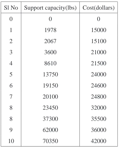
illustrating the interface of PIPESTRESS with Vitri for GA-based optimization. Table 3.2
shows the list of supports that are considered for the piping system, along with their cost
and support capacities. The following subsection describes the application of the proposed
GA for capital cost optimization by using this piping system as an example.
3.4.2
Capital cost optimization
The capital cost for various support types can be directly considered in the formulation
because such costs are readily available. The capital cost is given by
C =
nsup X
i=1
ci (3.11)
whereci is the capital cost of support at locationi. The above equation is used to compute
C in Equation 3.9. Tournament selection and stochastic universal selection [17] are tried and both appear to perform equally well for capital cost optimization.
It is necessary to verify that the solution generated by the genetic algorithm is the real
optimal solution or very close to the real optimal solution in order to make sure that the
proposed GA works for this problem. The real optimal solution for a given nreq can be
found by evaluating all possible solutions having nreq supports, which actually count to
nCnreq. It must be noted that this is possible only for smallnreqas the search space increases
The performance of the two crossover schemes is compared in Figure 3.4 with the
benchmark as the real optimal solutions fornreq = 3,4,5. The points in the graph represent
the best solutions that are generated over 5 runs of the genetic algorithm for eachnreq. It is
observed that the proposed crossover appears to produce better solutions, compared to the
uniform crossover. Moreover, the proposed crossover scheme generates the real optimal
solutions fornreq = 3,4,5. A notable difference between the two curves is that unlike the
proposed crossover, uniform crossover could not find the optimal solution fornreq = 3as
only a very few of the solutions with three supports are feasible.
The optimal solutions generated using proposed crossover, the cost values of which are
plotted in Figure 3.4, and their important properties for variousnreqare shown in Figure 3.6
and Table 3.3 respectively. The(θk/θkc)values of these solutions are shown in Figure 3.9.
Figure 3.4 also shows that the minimum cost solutions have minimum number of supports.
It should be noted that in an integer string representation, minimization for only the
num-ber of supports without explicitly considering the cost in the objective function would not
yield the same solution. Several different feasible solutions, with different support types
but equal number of supports would exist, each having a different cost. On the contrary,
minimization for the number of supports in a binary string representation will produce a
least cost solution as the sizing for support type can be delayed until the final step in each
3.4.3
Lifetime cost optimization
Lifetime cost includes the cost of replacement and outage in addition to the capital and
maintenance cost. Revenue losses due to unscheduled outage are much higher than the
maintenance and capital costs. Since specific estimates of lifetime costs are unavailable,
lifetime cost is represented as being proportional to some power of the support capacities,
i.e.,
C =
n
X
i=1
cfi (3.12)
We consider f = 1.2 even though actual values of f are expected to be much higher. Stochastic universal selection is used in the GA as it appeared to perform better than
tour-nament selection for this fitness function.
The results generated by using this cost function in the fitness function given by
Equa-tion 3.9 are shown in Figure 3.5. The figure shows two curves, one representing the results
generated using uniform crossover and the other using the proposed crossover. The
solu-tions represented by both the curves are the best solusolu-tions generated over 5 different runs of
the GA for eachnreq. The figure also shows the lifetime costs of the real optimal solutions
generated by enumeration, as described earlier for capital cost, fornreq= 3,4,5. The
pro-posed crossover scheme produces significantly better results due to reduced search space
and as in the case of capital cost, the proposed crossover scheme matches the real optimal
solutions for nreq = 3,4,5. In contrast to the results shown in Figure 3.4, it can also be
observed that there is a trade-off between the lifetime cost and the number of supports even
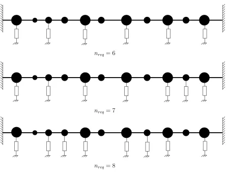
The optimal solutions generated by proposed crossover are shown in Figures 3.7 and
3.8. The important properties of these solutions are given in Tables 3.5 and 3.5. The
(θk/θkc)values of the solutions in Figure 3.7 are shown in Figure 3.10. It is observed from
the optimal solutions for both, capital and lifetime cost, that the desire of having the the
supports under lumped masses is not satisfied. In the following section, a lumped mass
parameterU is proposed to model this desirability as an objective in the GA.
3.5
Modified objective function
The optimal solutions for capital cost and lifetime cost corresponding to different values
ofnreq, are shown in Figures 3.6, and 3.7 and 3.8 respectively. It can be noted that most
of the supports in these solutions are not under the lumped masses. This is so because the
requirements for lumped masses has not been considered either explicitly or implicitly in
the objective function.
Consideration of support locations to be under the lumped masses requires some means
of quantification. While placing a support under all the heavy lumped masses would be
cost intensive, it is desirable to have as many lumped masses supported as possible. To do
so, we propose a lumped mass parameterU as follows:
U = mu
m
nu
nsup + 1
(3.13)
where mu is the total unsupported lumped mass and m is the total lumped mass in the
number of supports in a given solution.
The objective function given by Equation 3.9 can be modified to includeU as follows:
max
1
a∆δ+b∆σ+c∆θ+dC+e|nsup−nreq|+f U
(3.14)
wheref is a constant chosen appropriately to obtain solutions in which the heavier masses in the piping system are supported. Figure 3.11 shows the solution obtained by using
Equa-tion 3.14 as the objective funcEqua-tion. The cost of such soluEqua-tions, given in Table 3.7, are much
higher than the cost of the optimal solutions for the correspondingnreq in Figure 3.5. It
is desirable to consider only small deviations from the optimal cost (about 10% to 20%)
for accommodating issues such as the location of supports under lumped masses.
Conse-quently, a designer would benefit by generating alternatives that not only have costs in the
neighborhood of the cost optimal solution but also low values ofU. Next, we explore the role of a technique referred to as “Modeling to Generate Alternatives (MGA)” for
evaluat-ing alternative solutions.
3.6
Modeling to Generate Alternatives (MGA)
A traditional use of optimization is to create and run a model to find the “optimal”
so-lution. This solution, however, is rarely the best solution to the real problem because some
objectives and constraints may not have been explicitly stated in the problem formulation.
The omissions may be due to errors, the unquantifiable nature of certain issue or issues that
limitation of optimization applications. Modeling to Generate Alternative (MGA)
tech-niques [1, 4] use optimization to generate a small set of very different solutions. MGA is
an extension of single and multiple-objective mathematical programming techniques with
an emphasis on generating a set of alternatives that are “good” but “as different as possible.”
By generating these good yet different solutions, a decision maker can explore alternatives
that satisfy unmodeled objectives to varying degrees. These alternatives may be assessed
by the decision maker either subjectively or quantitatively.
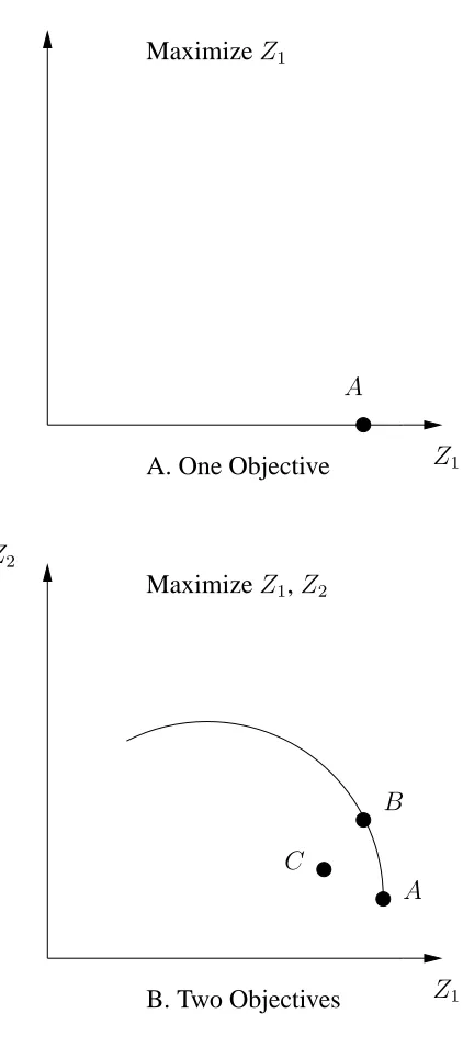
For instance, consider the problem of optimizing a single objective Z1. Let it have a solutionAas shown in Figure 3.12A. The addition of another objectiveZ2 would result in a trade-off, probably like the one shown in Figure 3.12B. SolutionB, which is inferior to
Aon the omission ofZ2, might be the most desirable compromise betweenZ1 andZ2 for the decision maker. In a similar manner, there might be a solution C which is not on the trade-off curve but is actually preferable to the designer in the presence of a third objective
Z3.
To further illustrate this idea, consider the following formulation of a design
optimiza-tion problem:
Maximizez =x+ 2y subject to
x+y ≤ 30
y ≤ 20
The decision space for the problem is shown as the shaded region in Figure 3.13A and the
slope of the objective function can be seen from a typical contour line at an arbitrary value,
80. Mathematical optimization correctly produces z = 50 at point A as the solution. Thus,
all other things being equal, the design would be< x, y >=< 10,20 >. The premise of MGA, however, is that all other things may not be equal, and that there may be problem
features not completely captured by the model. When those issues are considered, point
A may be less desirable overall than a point, call it B, originally deemed inferior by the
model. The issues involved in finding B and establishing the computer assistance needed
in this process are discussed below.
• Generating all feasible solutions suggests that one has no confidence in the model
-one would expect that point B optimizes the objective function nearly as well as A,
so only these good solutions need to be examined. This idea is illustrated in Figure
3.13B, where only those solutions that are within 10%of the optimal are retained.
• Available solutions should represent a cross-section of good solutions, so that, if B is
not actually among them, perhaps one of them is close enough from which to begin
“tinkering.”
• Since a decision maker can reasonably consider only a small number of designs, a
subset of these good solutions should be presented for inspection.
Baugh et. al. [1] illustrate these ideas with a topological truss optimization. Other MGA
pollution control as well as for land use and planning [6, 5, 19]. For the problem given
ear-lier, the first alternative can be found by changing the formulation to maximize a difference
metricδ, instead ofz and imposing the following constraint:
x+ 2y≥0.9(50)
This constraint ensures that the alternative generated is a “good” solution by searching the
objective space around the optimal solution. δfor this problem can be given by:
(x−10)2+ (y−20)2
which is the distance between the two points in the decision space. In this manner, an
alternative that is very different from the optimal solution in decision space but yet closer
to the optimal in objective space can be obtained.
3.7
Application of MGA to pipe support optimization
As noted from the discussion in the previous section, application of MGA requires
definitions of a reduced decision space and a difference metric to generate the alternatives.
For pipe support optimization, the decision space can be reduced by imposing the following
constraints:
Cmga ≤ k1Copt (3.15)
f itnessmga ≥ k2f itnessopt (3.16)
where k1 > 1 andk2 < 1; Cmga andCopt are the cost of the alternative and the cost of
the optimal solution respectively; f itnessmga and f itnessopt are the fitness values of the
alternative and the optimal solution respectively;Uallis an upper bound on the lumped mass
parameter specified by the designer, andUmga is the value of the lumped mass parameter
for an alternative solution; rmax is not considered for the MGA as it is found to be very
restrictive for the generation of alternatives as indicated in section 4.4.
Topology metric is used as the difference metric in the present study. This metric,
commonly known as “Hamming distance,” is applicable for binary strings. If the two
strings are given by < b1, b2, . . . , bn > and < c1, c2, . . . , cn >, the difference metric is
given by:
δ=
n
X
i=1
|bi−ci| (3.18)
The flowchart showing the incorporation of MGA in Vitri is given in Figure 3.14. The
alternatives generated using the topology metric in the MGA for nreq = 5 are given in
Figure 3.15. The important characteristics of the alternatives are listed in Table 3.8. The
values that are used for the MGA parameters in Equations 3.15, 3.16, 3.17 to produce
these results are as follows: Uall = 1.8, k1 = 1.25and k2 = 0.8. More lumped masses
are supported in the alternatives than in the optimal solutions given in 3.7. It is seen that
all the alternatives are very different from each other in topology. These solutions, which
are spread over a large expanse of the decision space, provide the decision maker with an
opportunity for tinkering with the solutions to generate better solutions. The alternatives
given in Table 3.10. A stricter constraint onUall is possible fornreq = 7as there are more
number of supports. The alternatives fornreq = 7are generated usingUall = 1.000, k1 =
1.3and k2 = 0.8. It should be noted that Copt = 1269610because the optimal solution
with respect to lifetime cost is that ofnreq = 5as seen from Figure 3.5.
In the process of generating these alternatives, various values forUall andk1 are tried.
It is seen that the chances of finding alternatives decrease rapidly as the values of Uall
and k1 are reduced. This observation supports the conclusion reached upon the end of the examination of the modified fitness function that it is excessively costly when all the
heavier lumped masses are supported. At the same time it should be kept in mind that this
piping system had a large number of heavy masses for the purpose of studying the effects of
these parameters. Actual piping systems may also have a large number of masses but they
are typically comparable in size to each other. Thus, there is a better chance of generating
much better solutions when the same is applied to a real piping system.
3.8
Application to real life piping system
The developed techniques are applied to the real life piping system shown in Figure
3.17. This piping system is in use in a nuclear power plant operated by Carolina Power
&Light. It consists of a 12.75 inch diameter Schedule 100 pipe loop that is anchored at
the reactor vessel. This loop is connected to an 18 inch diameter Schedule 120 pipe that
El Centro is used as the earthquake input to the piping system. The piping system has 75
support locations and each location can have a maximum of three supports, namely, one in
each of the principal directionsx,yandz. Some new issues that arise during the analysis of the real life piping system are discussed in section 4.5.
The results of the trade-off study between lifetime cost and the number of supports
for this piping system is given in Figure 3.18. Even though the trough of the trade-off
curve seems to be nearnreq = 25, the fundamental frequency of the piping system is much
higher than5Hz, because of the higher stiffness of the system. Designers normally prefer
the frequency of the piping system to be close to5Hz. The number of supports required to
have such a frequency is more likely to be nearnreq = 10.
3.9
Summary and conclusions
A GA-based approach for seismic design and performance evaluation of pipe supports
is discussed in the paper. Supports are modeled as rigid springs, permitting the use of a
binary string representation in the GA. The change in representation from integer to
bi-nary string is shown to produce a considerable reduction in the size of the search space
to be explored by the GA. Alternative seeding techniques to create populations, in which
the number of supports in its solutions is nearer to the required number, are explored.
The trade-off curves between various types of cost (capital or lifetime) and the number of
optimal solutions having a specified number of supports. The performances of the
pro-posed crossover scheme and uniform crossover are compared. A propro-posed lumped mass
parameter, U, is used in the MGA technique to generate useful alternatives. Finally, the practical applicability of the developed techniques is shown by applying them to a real
piping system.
The study shows that the solutions are primarily infeasible with respect to support
ca-pacities, and not because of the stress and the displacement constraints. Binary string
representation performs better than the integer string representation but it should be noted
that it is applicable only if the supports are modeled as rigid springs. The results show that
the proposed crossover scheme works better than uniform crossover. Optimization for
cap-ital cost is same as minimizing the number of supports whereas optimization for lifetime
cost is a multi-objective problem. The results from the use of the modified fitness function
show that it might be practically infeasible to support all the heavy lumped masses of a
pipe because of the high cost involved. MGA, using topology metric for difference and the
proposed lumped mass parameter as a constraint to reduce the decision space appears to
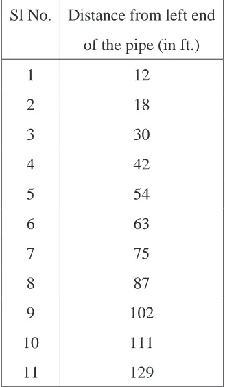
Table 3.1: Location of lumped masses along the pipe
Sl No. Distance from left end
of the pipe (in ft.)
1 12
2 18
3 30
4 42
5 54
6 63
7 75
8 87
9 102
10 111
Table 3.2: Cost and capacity of supports
Sl No Support capacity(lbs) Cost(dollars)
0 0 0
1 1978 15000
2 2067 15100
3 3600 21000
4 8610 21500
5 13750 24000
6 19150 24600
7 20100 24800
8 23450 32000
8 37300 35500
9 62000 36000
10 70350 42000
Table 3.3: Properties of optimal capital cost solutions given in Figure 3.6
nreq Cost U
θk
θkc
max
Frequency (Hz)
σi
σall
max
(in 10,000s)
3 108.000 0.873 0.921 5.489 0.980
4 131.600 1.448 0.951 9.632 0.593
5 162.900 2.000 0.952 9.398 0.429
6 189.000 0.930 0.974 8.768 0.457
7 203.300 1.122 0.938 8.760 0.457
8 218.300 1.146 0.977 8.753 0.459
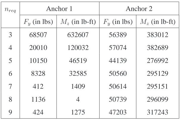
Table 3.4: Anchor forces of optimal capital cost solutions given in Figure 3.6
nreq Anchor 1 Anchor 2
Fy(in lbs) Mz(in lb-ft) Fy (in lbs) Mz (in lb-ft)
3 68507 632607 56389 383012
4 20010 120032 57074 382689
5 10150 46519 44139 276992
6 8328 32585 50560 295129
7 412 1409 50614 295151
8 1136 4 50739 296099
9 424 1275 47203 317243
Table 3.5: Properties of optimal lifetime cost solutions given in Figures 3.7 and 3.8
nreq Cost U
θk
θkc
max
Frequency (Hz)
σi
σall
max
(in 10,000s)
3 169.0406 0.873 0.921 5.489 0.980
4 131.3528 1.448 0.951 9.632 0.593
5 126.9610 2.000 0.952 11.007 0.244
6 131.4293 1.365 0.995 13.055 0.096
7 135.4763 2.000 0.988 11.720 0.257
8 143.7118 1.289 0.987 10.985 0.098
Table 3.6: Anchor forces of optimal lifetime cost solutions given in Figures 3.7 and 3.8
nreq Anchor 1 Anchor 2
Fy(in lbs) Mz(in lb-ft) Fy (in lbs) Mz (in lb-ft)
3 68507 632607 56389 383012
4 20010 120032 57074 382689
5 22687 136491 31272 157784
6 10298 46949 13769 53662
7 27542 166163 13777 54162
8 10724 49855 12969 59132
9 7599 29075 21149 101047
Table 3.7: Properties of optimal solutions obtained using Equation 3.14
nreq Cost (in ten thousands) U
6 244.8697 0.102
7 253.3298 0.077
8 202.6044 0.060
Table 3.8: Properties of MGA solutions fornreq = 5in Figure 3.15
Sl. No. Cost U
θk
θkc
max
Frequency (Hz)
σi
σall
max
(in 10,000s)
1 149.7216 1.099 0.991 9.953 0.547
2 153.1160 1.785 0.957 9.493 0.365
Table 3.9: Anchor forces of MGA solutions fornreq = 5in Figure 3.15
Sl. No. Anchor 1 Anchor 2
Fy (in lbs) Mz(in lb-ft) Fy (in lbs) Mz (in lb-ft)
1 19646 108406 53240 352690
2 14238 67781 38970 235801
3 18894 103855 34972 227664
Table 3.10: Properties of MGA solutions fornreq= 7in Figure 3.16
Sl. No. Cost U
θk
θkc
max
Frequency (Hz)
σi
σall
max
(in 10,000s)
1 163.0442 0.576 0.964 18.324 0.084
2 154.4800 0.862 0.992 14.578 0.210
Table 3.11: Anchor forces of MGA solutions fornreq = 7in Figure 3.16
Sl. No. Anchor 1 Anchor 2
Fy (in lbs) Mz(in lb-ft) Fy (in lbs) Mz (in lb-ft)
1 10974 50915 11610 38892
y
x
20 3 20 3 20 4 3 20 2
20 1
GA in Vitri
Fitness evaluation
Selection
Crossover
Mutation Seeding of population
Fitness evaluation Test
convergence for
No
Stop Yes
PIPESTRESS ANALYSIS Creating input file
based on string Find eigenmodes and
Generate response and perform modal analysis
by PIPESTRESS Parse output generated
support loads
1 2 3 4 5 6 7 8
1 2 3 4 5 6 7 8 1 0 0 1 0 1 0 1 1 2 3 4 5 6 7 8
1 2 3 4 5 6 7 8 1 1 0 1 0 0 1 0
1 1 0 1 0 0 0 1
1 0 0 1 0 1 1 0 Offspring 2 Offspring 1 Parent 2 Parent 1
S ={2,6,7,8};S1={2,8};S2 ={6,7}
proposed crossover real optimal solutions uniform crossover
150 200 250 300
2 4 6 8 10 12
C
api
ta
l
cos
t
(i
n
thous
ands
of
dol
la
rs
)
Number of supports 100
50
0
Figure 3.4: Results of multi-objective study for capital cost
uniform crossover proposed crossover real optimal solutions
140 150 160 170 180 190 200
2 4 6 8 10 12 14
cos
t
∝
capacity
1
.
2 (i
n
ten
thous
ands
)
Number of supports 130
120
110
nreq = 5
nreq = 4
nreq = 3
nreq = 6
nreq = 4
nreq = 3
nreq = 6
nreq = 5
nreq = 8
nreq = 7
nreq = 9