ABSTRACT
BADRAN-LOUCA, SERENA. Low Power Techniques for Video Codec Motion Compensation. (Under the direction of Dr. Rhett Davis).
A major milestone in the evolution of video coding standards is the well-known
H.264/MPEG-4 Advanced Video Coding (AVC). In January 2013 that was followed by
H.265/MPEG-5 High-Efficiency Video Coding (HEVC). Both of these standards achieve
substantial improvement in bit-rate efficiency compared to their predecessor and are the
standard of choice in many application standards such as HD, DVD, HD-DTV.
With the proliferation of handheld devices, emphasis on reducing power consumption
and increasing battery life is growing, thus making the improvement of power efficiency the
main goal of any decoder implementation. However, most of the current power solutions focus
solely on reducing memory accesses, the largest power drain. Other aspects that are not getting
as much attention include memory access efficiency, memory power down, and pipeline
efficiency. Power for these aspects can be reduced with new architectures for Memory Access
Arbitration and Reference Data Scheduling. As shown in this work, using these techniques
results in 87.67% off chip memory power reduction and reduces the number of memory
© Copyright 2015 Serena Badran-Louca
Low Power Techniques for Video Codec Motion Compensation
by
Serena Badran-Louca
A dissertation submitted to the Graduate Faculty of North Carolina State University
in partial fulfillment of the requirements for the degree of
Doctor of Philosophy
Computer Engineering
Raleigh, North Carolina
2015
APPROVED BY:
_______________________________ ______________________________ Rhett Davis Paul Franzon
Committee Chair
ii DEDICATION
To Sana, Kassem, Tony, Stefano and Rafaella. You are my everything.
BIOGRAPHY
Serena Badran-Louca was born in Beirut, Lebanon. She earned her Bachelor’s degree in
Electrical Engineering from the American University of Beirut in June 1997. She started a
coop position in March 1998 with ABB Electric Systems Technology Institute on the
Centennial Campus of North Carolina State University and consequently obtained a Masters
Degree in Computer Engineering from NCSU in Dec 2000. She started her career as an ASIC
Engineer with AMCC in Jan 2001 until July 2002. After that she returned to NCSU and started
taking Non-Degree courses in the ECE department until officially enrolling in the Ph.D
program in March 2004. At the same time, she started a full time position at Qualcomm Incorp
as a Hardware Engineer. She continues to work at Qualcomm as a logic designer in the
processor group.
Serena is married to Tony Louca, a fellow AUB/NCSU alumni. They have a four and half year
iv ACKNOWLEDGMENTS
First and foremost, I would like to thank my advisor Dr. Rhett Davis for his technical and
personal mentoring. His positive and encouraging attitude really helped push me against all
the odds. His constructive supervision was a source of encouragement and helped me not lose
sight of my goals. I would also like to thank all my professors at NC State especially during
my Masters degree. Their expertise and passion for teaching is very inspiring.
I would also like to thank my coworkers and managers at Qualcomm Inc. for their support,
especially during the early years of my PhD. I am proud to work at a company that values the
continuing education of their employees so much.
To my parents, I thank you for all the sacrifices you made to make sure I had a good education.
You set a perfect example for working hard and being professional and passionate about what
you do. Thanks for all your love and support throughout the years, without it I wouldn’t have
been able to accomplish much.
Last and certainly not least, to my amazing husband Tony. This dissertation would not have
been possible without your help and support. It has been a long and frustrating road, but you
were with me every step of the way. From brainstorming for ideas, to helping me in my
research and providing inspiring discussions, you were always there even after long days at
work. You believed in me and supported me unconditionally and for that I am eternally
TABLE OF CONTENTS
LIST OF TABLES ... vi
LIST OF FIGURES ... vii
CHAPTER 1: Introduction ... 1
1.1. Background ... 1
1.2. Motivation ... 5
1.3. Review of Present Status ... 8
1.3.1. Reducing reference data accesses ... 8
1.3.2. Pipeline Efficiency ... 9
1.4. Proposed Techniques ... 9
1.4.1. Memory Access Arbitration ... 10
1.4.2. Reference Data Scheduling ... 10
CHAPTER 2: Power Reduction Techniques ... 11
2.1. Memory Access Arbitration ... 11
2.2. Reference Data Scheduling ... 19
2.2.1. Reference Pixel Re-use ... 19
2.2.2. Reference Data Prefetching ... 21
CHAPTER 3: System Model ... 24
3.1. Model Architecture ... 24
3.1.1. Motion Compensator ... 25
3.1.2. Deblocking filter ... 26
3.1.3. Prefetcher ... 27
3.1.4. Arbiter ... 28
3.1.5. Cache Manager ... 34
3.1.6. Pixel Cache ... 36
3.1.7. Memory ... 37
3.2. Model Interfaces ... 37
3.2.1. Arbiter ... 38
3.2.2. Cache Manager ... 38
Table 4: Cache Manager Interfaces ... 39
3.2.3. Pixel Cache ... 39
CHAPTER 4: Experimental Results ... 40
4.1. Model Assumptions ... 40
4.2. Memory Access Arbitration ... 44
4.3. Reference Data Scheduling ... 47
CHAPTER 6: Conclusion ... 53
III. REFERENCES ... 54
vi LIST OF TABLES
Table 1: Memory access ratio of H.264 decoder modules (W: frame width, H: frame height) 5
Table 2: Interpolation filters and reference data size of one MxN Luma partition ... 19
Table 3: Arbiter Interfaces ... 38
Table 4: Cache Manager Interfaces ... 39
Table 5: Pixel Cache Interfaces ... 39
LIST OF FIGURES
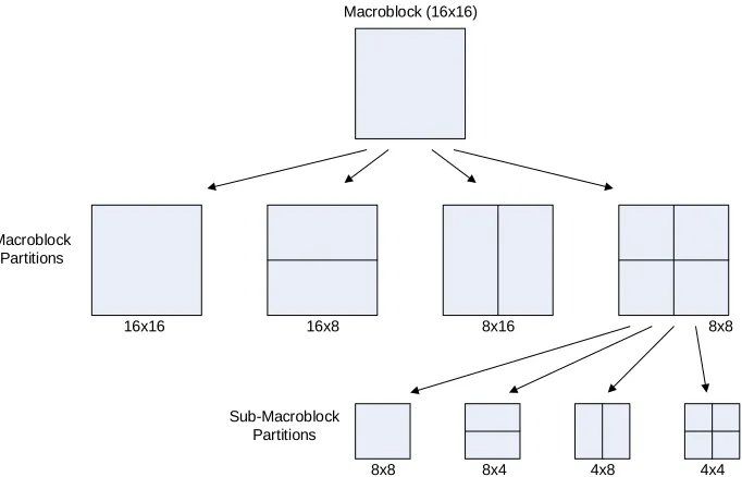
Figure 1: Partitioning of macroblock & sub-macroblock for motion compensated prediction 2
Figure 2: H.264 Encoder ... 3
Figure 3: H.264 Decoder... 3
Figure 4: Power profile of H.264 system ... 5
Figure 5: Full pixel samples (shaded and with upper case letters) and sub-pixel sample positions (unshaded with lower case letters) for quarter sample luma interpolation ... 19
Figure 6: Horizontal and vertical data reuse across 4x4 sub-partitions ... 20
Figure 7: Read pending queue. ... 22
Figure 8: System model top level diagram. ... 24
Figure 9: Arbiter details ... 29
Figure 10: Foreman frame showing partition choices. ... 41
Figure 11: Memory Access Arbitration Results ... 46
Figure 12: Motion Compensator Hits/Misses in the Cache vs. Cache size ... 47
Figure 13: Motion Compensator hit rate in the Cache vs. Cache Size. ... 48
Figure 14: System Power Reduction vs. Cache Size ... 49
Figure 15: Cache Cost vs. Size ... 50
Figure 16: System Cost vs. Cache Size ... 51
Figure 17: Motion Compensator Hits in the Cache ... 51
Figure 18: Matrices of the three different transforms applied in H.264 ... 61
1
CHAPTER 1: Introduction
Nearly every mobile computing device today contains the ability to display streaming video. Specialized video CODECs (enCOder/DECoder pair) are an expected
component in most media processors, and the power consumption of these CODECs have a large impact on the battery life and customer satisfaction with their smart-phones and tablets. This work seeks to develop new techniques to reduce the power consumption of video CODECs and extend the battery life of these mobile devices by focusing on the largest contributor off-chip memory power.
1.1.
Background
16x16 16x8 8x16 8x8 Macroblock
Partitions
Sub-Macroblock Partitions
8x8 8x4 4x8 4x4
Macroblock (16x16)
Figure 1: Partitioning of macroblock & sub-macroblock for motion compensated prediction
Figure 2 is the block diagram of the H.264 encoder. In the encoder, a decoder path like the one in Figure 3 is used. Like previous ISO/IEC video coding standards, only the
decoder and not the CODEC (enCOder/DECoder pair) is standardized. By restricting the bit stream and syntax, and by defining the decoding process, all standard decoders will produce similar output given an encoded bit stream conforming to the standard constraints. Such a limitation of the scope permits implementation freedom in a manner appropriate to the application.
3 Figure 2: H.264 Encoder [3]
Figure 3: H.264 Decoder [3]
There are two types of prediction P, intra prediction and inter prediction. Intra prediction exploits the spatial redundancy among neighboring blocks in a video frame whereas inter prediction exploits the temporal redundancy of a video sequence. Finally a filter is used to eliminate the blocking artifact that is a disadvantage of block-based video coding. This deblocking filter helps generate a smoother picture.
5
1.2.
Motivation
The following figure shows the power profile of the H.264 decoder. The motion compensation engine and the off chip memory, with the highest power percentages, are clearly the ideal candidates to focus on for a low power solution.
Figure 4: Power profile of H.264 system [5]
Table 1 shows the breakdown of memory accesses among various blocks in the H.264 decoder. Again, the motion compensation engine is responsible for the biggest portion of memory accesses.
Table 1: Memory access ratio of H.264 decoder modules (W: frame width, H: frame height)[7]
Deblocking Filter, 17%
Motion Comp., 26% Memory,
20%
Intra, 9%
Others, 2%
Q-1, 3%
Syntax,
12% Hadamard, IDCT 6%
CAVLC, 5%
Module Max memory access bytes Ratio (≈) Ref. picture store W*H + 2*(W/2)*(H/2) 10 %
De-blocking (W/16)*(H/16-1)*(16*4+4*4*2)*2 5% Display feeder W*H + 2*(W/2)*(H/2) 10%
One interesting observation from Table 1 is that, even though the de-blocking filter and the motion compensator are touching the same number of unique pixels (same frame size), motion compensation has 15X the memory accesses of the de-blocking filter. This is because the interpolation filter reads the same reference pixel multiple times: when the pixel is interpolated and when the pixel is in the neighborhood of
another pixel being interpolated.
Current techniques being used to reduce memory accesses highlighted above include:
Only read the neighboring pixels needed for interpolation based on the motion
vector [7].
Cache neighboring reference pixels locally to prevent reading them again while interpolating the next sub-partition [9].
These techniques, while reducing the number of memory accesses, do not take advantage of some opportunities that would offer additional power savings.
Memory power down: When the required memory bandwidth is less than the
7
Reference Pixel Reuse: Depending on the sub-partition motion vector, the
motion compensator can require up to 6 neighboring pixels to estimate one pixel in the new frame. Using a local cache and allowing reference pixel caching across MBs boundary we can make sure that every reference pixel is not read more than once from memory thus bounding the number of memory accesses to the reference frame size. According to Table 1 this would reduce the motion compensator memory reads by up to a factor of 15.
Prefetching reference data: Different sub-partitions estimated by the motion
compensator could have different motion vectors requiring a different interpolation filter to be used. The filter pipeline can be made to re-configure on the fly so that it does have to flush the previous sub-partition data before starting on the new one. For this to be effective, reference data for the new sub-partition has to be available right when the last reference pixel of the previous sub-partition goes into the filter pipeline. This could be achieved by prefetching
reference data from the next sub-partition ahead of time. Also, by doing this, external memory could be put in power down mode for a longer period before the motion compensator runs out of reference data.
1.3.
Review of Present Status
Researchers have attempted to tackle the problem of reducing memory accesses using approaches which can be categorized as follows:
1.3.1.
Reducing reference data accesses
According to the H.264 specification, the sub-pixel filter in the motion compensation requires, based on the motion vector, up to six reference pixels to be read in order to produce one pixel. These reference pixels might come from neighboring sub-partitions which also need to be read from off chip memory. By default, all neighboring reference pixels are read to perform interpolation, a total of (M+5) x (N+5) pixels. However, the interpolated sub-pixel type, and therefore the interpolation filter used, can be determined from the motion vector. [7], [13] and [14] show how this information can be used to only read the neighboring pixels needed by the interpolation filter in question.
9
1.3.2.
Pipeline EfficiencyThe interpolation of pixels in a sub-partition requires the use of pixels from neighboring sub-partitions. These pixels will then be re-used when interpolating these neighboring sub-partitions. To minimize memory accesses, researchers use a cache to store the neighboring pixels locally to prevent reading them while interpolating the next
sub-partition as shown in [9]. Two new observations in this work extend the concept from [9] to increase memory and pipeline efficiency:
The caching concept may be extended beyond the macroblock boundary. The idea
is that once you move from one macroblock to another you could use cached reference pixels just as you would within a macroblock.
When transitioning from one sub-partition to another, we could eliminate pipeline stalls waiting for the filter to finish with the current sub-partition until starting on the next one. This could be achieved by prefetching reference data for the next sub-partition ahead of time and switching the filter pipeline on the fly to start processing the next sub-partition. Note that the next sub-partition could potentially have a
different motion vector which means that the filter pipeline needs to be modified to handle different motion vectors simultaneously.
The above extensions would allow reference pixel data to be always readily available to the interpolator and increase pipeline efficiency. This is the essence of the second technique in this research; Reference Data Scheduling.
1.4.
Proposed Techniques
1.4.1.
Memory Access ArbitrationReducing memory accesses reduces memory utilization and creates an opportunity to power down memory devices when not in use. By bunching up memory requests, active memory request scheduling guarantees idle periods and eliminates the latency penalty of memory power down events. The request scheduling is done by the memory arbiter
described in section 4.1.4 and has the following assumptions:
o The total required memory bandwidth is a fraction of the available bandwidth. This might be a low performance scenario.
o The two clients accessing memory, the deblocking filter and the motion compensator, have built-in latency tolerance without affecting performance. The result is reduction of power dissipated by external memory devices with noticeable impact on performance.
1.4.2.
Reference Data SchedulingEliminating pipeline stalls helps reduce power dissipation by increasing the amount of time the logic could be power gated or clock gated. To that end, surveyed research made heavy use of reference data caching to reduce stalls due to memory fetches. The following techniques offer additional reduction of pipeline stalls:
o Extend caching to re-use pixels across macro blocks instead of limiting it to sub-partition inside the macro block.
o When switching to a new sub-partition, use the new motion vector to prefetch reference data ahead of time.
11
CHAPTER 2: Power Reduction Techniques
2.1.
Memory Access Arbitration
For a given configuration, if B is the total available memory bandwidth and X is the memory bandwidth required by the motion compensator, then theoretically, we should be able to power down the memory modules (B-X)/B of the time. To get close to this power down ratio, a memory arbiter would take requests from the motion compensator and the deblocking filter and issue them to the memory devices. The memory arbiter would have the following specifications:
1) Batching up memory requests and issuing them in a bursty manner while allowing the memory modules to be put in power down mode in between bursts. The arbiter would have programmable low and high watermarks. When the number of batched requests exceeds the high watermark, the arbiter will start issuing the requests until the number of queued requests reaches the low watermark.
2) Memory power down causes the motion compensator to see larger memory read latency than normal. This would require the compensator to implement latency tolerance by prefetching data in advance and storing it in a latency hiding buffer. When the data in the buffer runs low, the predictor can signal the arbiter that it is in critical need of data which the arbiter will try to service as soon as possible.
3) To ensure that the write stream coming from the deblocking filter is also bursty, a coalescing buffer will be used to accumulate the writes. This buffer will also implement a high and low watermarks policy to decide when to flush the buffer. 4) Since memory devices are not efficient when read and write accesses are finely
interleaved, the memory arbiter will bunch these accesses to minimize overhead.
B. Sizing the coalescing buffer for blocking filter writes C. Arbitration Policy and Assumptions
Here we present calculations to determine the requirements for each of these aspects. This is a feasibility analysis to determine that these requirements can be realistically met in an energy-saving CODEC architecture.
A. Sizing the latency buffer for motion compensation access
Latency Buffer (LB) Size = Read Bandwidth (RBW) * Read Latency (RL) Ideally we want to design the smallest latency buffer to support the highest performance configuration, so :
Min LB size = Max RBW * Min RL i. Read Latency (RL)
RL = Arbiter holdoff + Memory Pwr up + Read return latency Where
- Arbiter holdoff is the time between the arbiter seeing the read request and acting on it.
- Memory power up is the time between the arbiter deciding to power up memory until it can issue the read request.
- Read return latency is the time between issuing the read request and the read data arriving at the input of the latency buffer.
Since we are using the calculation of RL to size the latency buffer, we need to look for the worst case latency. This should include programmable knobs like arbiter holdoff. Furthermore, the time between issuing the read and when the read data actually returns is only a handful of clocks, thus the equation for RL reduces to: RL = Memory Pwr Up
13 ii. Bandwidth (BW)
BW is dependent on:
Num. of frames/sec
Size of frames
The sampling format ( 4:2:2, 4:4:4…)
Number of reference frames needed to predict current frame
The read BW for motion compensation can be summarized as follows:
I.
BWMC = Num of frames/sec *
Num of luma and chroma samples/frame * Num of bits/sample *
Num of Reference Frame(s)
The write BW for the deblocking filter is the same as the read BW for the motion compensation when the number of reference frames is one. This is because the deblocking filter need only to write one frame at a time.
BWFilter = BWMC / # reference frames
The key assumption here is that the motion compensator is able to re-use pixels across the whole frame and no reference pixel is read twice. This is why the Reference Data Scheduling technique is important.
The total BW for the H.264 decoder can be described as follows.
f * # lines * # luma/line
where f = 3 (4:4:4) 2 (4:2:2) 3/2 (4:2:0)
Total BW = BWMC + BWFilter
= (1+ # reference frames) * #frames/sec *
So for 1080p: = (1+ # reference frames) * 25 *
2 * 1920 * 1080 * 8
= (1+ # reference frames) * 400 * 1920 * 1080
Worst case ( B macroblock , bi predicted) => # reference frames = 2 => Total BW for 1080p (worst case) = 296 MB/s
Assuming
=> 8B * 800 * 0.7 = 4.480MB/s = 4.48GB/s
Total available BW from a fast memory configuration is:
=> 1.86GB/s
Total available BW from a slow memory configuration is:
=> 1.12GB/s
From all the above numbers we can conclude that we have room for memory power down. Min LB = Max BW * Mem PwrUp
= 296MB/s * 200 tck
= 222Bytes 64b memory = 8B DDR3 800MHz 70 % efficiency
32b memory = 4B DDR2 667MHz 70 % efficiency
15 222Bytes is pretty small, so we have plenty of room in the LB size. However we should size the buffer based on a “typical” memory read latency. This typical memory is somewhere between the “best” and “worst” case latency.
Best Case Latency
a. Memory is already powered up
b. The read is to a page that is already open
c. The bus is not being used to drain the write buffer ( for the deblocking filter accesses)
Average Case Latency
a. Memory is already powered up
b. The read is not to a page that is already open
c. The bus is being used to drain the write buffer ( for the deblocking filter accesses)
Worst Case Latency
a. Memory is not powered up
b. The read is not to a page that is already open
c. The bus is being used to drain the write buffer ( for the deblocking filter accesses)
Note that the worst case latency could be reduced if the decoder pipeline provided an early “Need to Read” signal which will hide some of the power up latency. What this means is that if for some reason the actual latency turned out to be at our typical latency, then the motion compensator will stutter. However, this should be rare due to early power up and some arbiter optimizations. Thus, using typical latency to size the buffer should be a reasonable compromise to save power and will be verified by simulation.
Average latency is a function of the following:
1. The read is not to a page that is already open: We need to issue a page management command
value is when a targeted bank has a page operation such that we need to close an open page and open a new one.
2. The bus is being used to drain the write buffer: Assume we can interrupt the write stream and then add some guard band to account for letting writes go so that we don’t block the filter.
Therefore latency = precharge activate read data
Latency = trp + trcd +tcl
DDR2-800E = 15 + 15 + 15 = 45ns DDR2-667D = 15 + 15 + (5x300) = 45ns DDR2-533C = 15 + 15 + (4x3.78) = 45 ns
So typical latency = 45 ns (this is from pin to pin)
=> Latency Buffer Size = 296 MB/s * 45ns = 13B
The fact the buffer need to cover memory latency is small is good news. This means that we could increase the latency tolerance of the motion compensator at a relatively low cost which would have two advantages:
1- Keep memory powered down for longer stretches of time and exit power down mode less frequently.
2- Allow bigger batches of write requests which would increase the memory bus efficiency by having less turnaround time.
17 B. Sizing the coalescing buffer for blocking filter access
Requirements for the write buffer:
Needs to be deep enough to absorb deblocking filter writes at the frame rate *
frame size for the duration required to keep the motion compensation from stuttering.
Coherency. Make sure that frames that are being read by the motion estimator
are flushed first if it is in the write buffer.
Need to provide an urgency indicator to the arbiter when close to full.
The depth of write buffer affects the read latency and the BW efficiency. A write buffer would allow the memory arbiter to bunch writes and reads and prevent costly turn around time on the memory bus. It also reduces the chance of a read burst getting interrupted to serve writes.
In a similar fashion to our calculation of the latency buffer for the motion compensator,
BW filter = 400 * 1920 * 1080
= 98MB/s
Another configurable knob is how long to hold off writes, either due to memory power down or because the arbiter is doing reads, before issuing them to
memory. Assume we block for T secs,
=> 98MB/s * T sec => 98T MB
C. Memory Arbiter
There are two key points:
i. Arbitration policy
The arbitration policy is configurable via the following knobs:
Request bandwidth: Each client will have a programmable request bandwidth
knob which tells the arbiter how many requests this client needs to issue before it can switch to the other client.
Sticky timer: Each client will have a programmable timer which tells the arbiter
how many cycles to park on a client that has not satisfied its request bandwidth but has not request before it can switch to the other client.
We’re assuming just 2 core clients, the motion compensator (C1) and the filter (C2). So basically switch from C1 to C2 if:
C1 met its BW sharing & (C2 has a request || C1 didn’t
have a request for X1 cycles)
C1 did not meet its BW sharing && ( C2 has a request
& C1 did not have a request for X1 cycles)
where X1 is the number of cycles to wait for C1 requests before bailing out on C1.
i. Power up/down
Self refresh
Active power down ( check the spec on semantics & how each mode is
entered and exited)
Entry and Exit Criteria:
19
2.2.
Reference Data Scheduling
2.2.1.
Reference Pixel Re-use
In motion compensated prediction, based on the interpolation type (see Table 2 below), reference pixels from neighboring sub-partitions might be used when interpolating pixels in the current sub-partition.
Table 2: Interpolation filters and reference data size of one MxN Luma partition Interpolation position Interpolation filters Minimized reference
data size
G No MxN
a,b,c 6-tap horizontal Mx(N+5) d,h,n 6-tap vertical (M+5)xN e,f,g,i,j,k,p,q,r 6x6 tap filter (M+5)x(N+5)
A aa B
E F
C bb D
K L
G a b c H I J
M N P Q
R S
s
g g d e f h i j n p q
g k r
m
T hh U
e
e ff
cc d
d
Table 2 shows how to determine the interpolation type from the motion vector. Example:
Given reference pixel G with a motion vector (½, ½), the predicted pixel according to Figure 5 would be pixel j. Now, according to Table 2, predicting pixel j requires a 6x6 tap filter and (M+5) x(N+5) reference data.
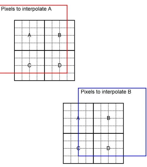
Figure 6: Horizontal and vertical data reuse across 4x4 sub-partitions
Figure 6 shows how pixels that were read to predict one sub-partition can be re-used when
21 some of the same reference pixels used for A will also be used when interpolating sub-partition B pixels.
The idea here is to keep the common pixels around to prevent reading them twice and
increase memory access efficiency. A key challenge is when the two neighboring sub-partition A and B have different sizes and/or motion vectors. In this case, the prediction logic needs to be smart enough to know how to re-position the re-used pixels in the input buffer to the interpolation logic.
The pixel reuse logic determines whether an entry read from the reference pixel cache needs to be marked for reuse. At a high level, it takes as input from the motion compensator:
Current sub partition bounding box + motion vector
Next sub partition bounding box + motion vector
2.2.2.
Reference Data Prefetching
When the motion compensated prediction moves from one sub-partition to the next, the motion vector value might change which would change the type of the interpolation filter used, what reference pixels are pushed through the filter, and the crossbar configuration.
During the sub-partition switch, our goal is for the pixel cache and the crossbar to feed the interpolator with data every clock cycle with no stuttering. While the current sub-partition is being interpolated, a prefetcher will look ahead at the next sub-partition and, based on the
motion vector, determines what reference data needs to be read from memory. It will prefetch the data into the pixel cache so that it is ready for interpolation.
Current sub partition bounding box + motion vector
Next N sub partitions bounding box + motion vectors.
For these 2 concepts of pixel reuse and data prefetching, a pixel cache is needed and that is managed by a Cache Manager. The Cache Manager interfaces to the memory arbiter and the reference Pixel Cache and its main function is:
1. Keeps track of what lines are in the cache so that we can dismiss MC reads and prevent them from being issued to memory.
2. Makes sure that data is read from the cache in the same order that the MC issued the read request.
3. Manages the Read Pending Queue and Cache Lookup Table structures. a. Read Pending Queue:
i. Contains entry for all requests issued to memory ii. Contains a list of all MC reads (issued + dismissed)
iii. Indicates whether read data is available ( hit in the cache or coming from memory)
Figure 7: Read pending queue.
b. Cache lookup table. Each table entry has: i. Line Address
23 1. Empty
2. MC Pending
3. MC Prefetch Pending 4. Prefetch
5. Reuse
iii. Age counter 4. Invalidates lines on writes
5. Implements the following cache entry replacement policy
if (MC request) grab an empty line
else grab a prefetched line (FIFO) else grab a reused line (FILO)
else hold off the request (bad – means the latency buffer sizing was incorrect)
else if (Prefetch request) grab an empty line
else grab a prefetched line (FIFO) or hold off request based on input from prefetcher to prevent trashing.
CHAPTER 3: System Model
3.1.
Model Architecture
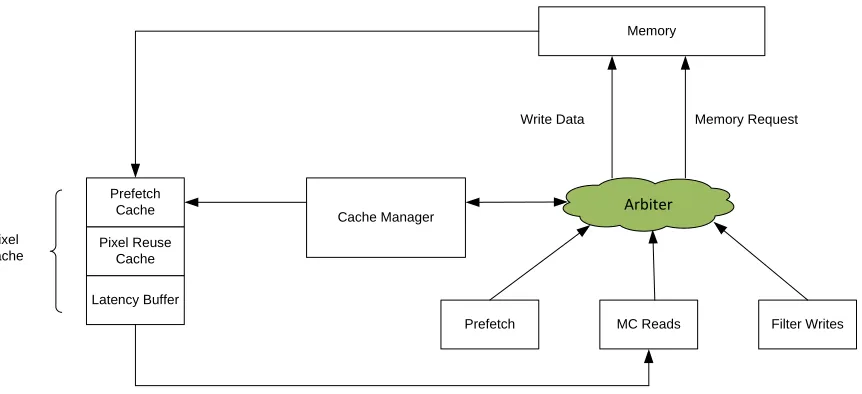
The following figure shows the high level block diagram of the system model used to verify the theory behind these techniques. All blocks in this figure are implemented using SystemC classes. The prefetcher, motion compensator and deblocking filter will issue read or write requests to memory. The arbiter will select between these requests, snoop and update the cache, and issue requests to memory. The cache manager implements the tag cache lookup along with the caching policies. The pixel cache handles memory read return data as well as providing the motion compensator with read data.
Pixel Cache
Latency Buffer
Memory Request
Pixel Reuse Cache Prefetch
Cache Cache Manager
Prefetch MC Reads Filter Writes Write Data
Memory
Arbiter
25 3.1.1. Motion Compensator
The motion compensator class instantiates a traffic generator class which implements the following functionality:
a. Reads a sequence of blocks from a user file. The file contains a list of different size macro blocks for the motion compensator to read from memory. A batch of macro blocks forms a sub partition. At the end of a sub partition, the user file will have a command to pass the sub-partition to the deblocking filter which will write it to
memory.
b. Before passing them to the motion compensator, the generator expands macro blocks to include neighboring reference pixels. The number of neighboring pixels included depends on the motion vector for this macro block.
c. After expanding a macro block, the generator will dice it into 2x2 pixel regions (quads) each with a corresponding memory address.
d. The generator will go over all the macro blocks specified in the user file until it reaches the end of the block sequence.
Here is a snippet of a user file describing a block sequence:
IMAGE WIDTH :256 Image dimensions used for IMAGE HEIGHT : 256 address generation.
0 : 0,0 7,7 Upper left and lower right coordinates of macro block to read from estimate.
1 : 0,0 7,7 Write command for passing to the deblocking filter.
0 : 8,0 11,3
0 : 12,0 15,3 Macro blocks forming a Sub-partition.
The motion compensator will issue one read request to memory for each quad of pixels it receives from the traffic generator. It receives quad data, in order, from the pixel cache which it processes at a configurable rate. The motion compensator can have a certain number of read requests in flight that it cannot exceed. A read request is retired after the corresponding response has been received from the pixel cache and processed.
The motion compensator is responsible for indicating to arbiter, via the mc_arb_urgent signal, when it is running low on read data. The arbiter uses this information to prioritize motion compensator reads over other memory clients and to power up memory if needed. The motion compensator derives its urgency in the following manner:
a. The mc_arb_urgent signal is set high (urgent) when the number quad data in the input buffer goes below a configurable low watermark.
b. The mc_arb_urgent signal is set low (normal) when the number of quad data in the input buffer goes above a configurable high watermark.
Finally, the motion compensator is responsible for conveying a sub-partition to the deblocking filter after issuing read requests for all the macro blocks in that sub partition.
3.1.2. Deblocking filter
The deblocking filter is responsible for removing blocking artifacts from a sub-partition that has been estimated by the motion compensator. It accepts “blocks” from the motion
compensator which are defined by their upper left and lower right pixel coordinated.
typedef enum {
BLOCK_RD = 0, BLOCK_WR = 1 } block_type;
27 int x;
int y; } location;
typedef struct {
location up_left; location lo_right; block_type type; } block;
The filter will process the block and write it to memory one quad at time at a configurable rate. The filter is responsible for computing the memory address of every quad using the same parameters and computations as the motion compensator’s traffic generator.
Finally, the write data buffer for the filter lives in the arbiter class. As described later, the arbiter, based on the write buffer occupancy, will derive the urgency of the filter’s memory write requests.
3.1.3. Prefetcher
The prefetcher’s role is to look ahead in the block sequence and read reference pixels for macro blocks that the motion compensator has not started processing yet. The advantage of doing that is to reduce the motion compensator’s read latency (i.e. no stuttering) and, more importantly, minimize powering up memory as the motion compensator can be serviced directly from the cache.
The prefetcher will receive future macro blocks from the motion compensator’s traffic generator using the same “block” packet defined above. It will dice the block into quads, generate a memory address for every quad and issue a request to memory.
later, the arbiter will service prefetch requests opportunistically when the memory is powered up.
Finally, the prefetcher issues it requests at a configurable rate which allows for an additional knob to reduce the prefetch request traffic.
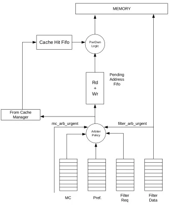
3.1.4. Arbiter
The arbiter class will act as a consumer for the three memory requestors in the system. The arbiter will have an input fifo to buffer a certain number of requests from each requestor before it will start blocking new requests until a slot in the fifo becomes available.
The arbitration policy used by the arbiter is designed to meet to the following criteria:
1. Prioritize clients that are urgent in order to guarantee a certain performance level for the system.
2. Maximize the memory bus efficiency by reducing the read to write and write to read turnaround times.
3. Power down memory as aggressively as possibly while adhering to the above two criteria.
29
MC Pref. Filter
Req
Filter Data Arbiter
Policy Rd + Wr PwrDwn
Logic
From Cache Manager
Pending Address
Fifo MEMORY
filter_arb_urgent mc_arb_urgent
Cache Hit Fifo
Figure 9: Arbiter details
The filter_arb_urgent signal is set high (urgent) when the number quad data in the
write buffer goes above a configurable high watermark.
a. The filter_arb_urgent signal is set low (normal) when the number of quad data in the write buffer goes below a configurable low watermark.
Here is the pseudo code used to implement the arbiter’s policy:
arb_pick_mc = FALSE;
arb_pick_filter = FALSE;
arb_pick_prefetcher = FALSE;
if (mc_arb_urgent)
arb_pick_mc = TRUE;
else if (cur_filter_urgent)
arb_pick_filter = TRUE;
else if (doing_reads && MC has requests)
arb_pick_mc = TRUE;
else if (doing_reads && Preftcher has requests)
arb_pick_prefetcher = TRUE;
else if (doing_writes && filter has requests)
arb_pick_filter = TRUE;
else if (MC has requests)
arb_pick_mc = TRUE;
else if (filter has requests)
arb_pick_filter = TRUE;
else if (Preftcher has requests)
arb_pick_prefetcher = TRUE;
Here is the pseudo code for the logic that is trying to minimize read to write turn around.
31 num_back2back_reads++;
num_back2back_writes=0;
if (num_back2back_reads == ARB_MAX_NUM_B2B_READS)
num_back2back_reads=0;
doing_reads = FALSE;
doing_writes = TRUE;
else
doing_reads = TRUE;
doing_writes = FALSE;
else if (arb_pick_filter)
num_back2back_writes++;
num_back2back_reads=0;
if (num_back2back_writes == ARB_MAX_NUM_B2B_WRITES)
num_back2back_writes=0;
doing_writes = FALSE;
doing_reads = TRUE;
else
doing_writes = TRUE;
doing_reads = FALSE;
Once the arbiter picks a winner from the three potential requestors, it will: a. Pop the request from the winner’s request fifo.
b. Send the request to the cache manager to snoop the cache.
c. Push the request into the Pending Address FiFo to wait for the hit/miss response from the cache manager.
Miss: The data corresponding to the request is not present in the pixel cache. The arbiter
can go ahead and issue the read request to memory since the cache manager already reserved an entry for it.
Hit: The data corresponding to the request is present in the pixel cache. The arbiter should
dismiss the read request to memory since the cache manager already locked the corresponding entry in the pixel cache to prevent it from getting evicted.
Note that, for reads, the arbiter needs to tell the cache manager whether the request source is the motion compensator or the prefetcher. This is because the Pixel Cache will need to know whether to forward the response data to the motion compensator or keep it in the cache if the if the source was the prefetcher.
Also, to be able to stream reads to memory, the interface between the arbiter and the cache manager will be pipelined where the arbiter could have up to N requests outstanding before it could get the response for the oldest outstanding request. N is computed as the latency from
the arbiter request to the cache manager’s response (assuming no blocking due to cache being full) divided by the rate of the arbiter requests.
For writes requests, the arbiter will send a request to the cache manager to invalidate the line if it is present in the cache. This is needed to make sure no stale data in the pixel cache are sent to the MC.
The cache manager response packets to the arbiter will go into the Cache Hit FiFo. Here’s the pseudo code of the logic used by the arbiter to drain the Pending Address and Cache Hit FiFos:
if (Head of Pending Address FiFo is a write request &&
Write data buffer has quad data)
Pop an entry from the Pending Address Fifo;
Take quad data from the write buffer.
33 else if (Head of Pending Address Fifo is a read &&
Cache Hit Fifo has a valid entry)
if (cache response is a miss)
Issue read request to memory
Pop an entry from the Pending Address Fifo
Pop an entry from the cache Hit Fifo
Note how read requests which cache response is a hit will be dropped inside the arbiter and not issued to memory.
Finally, the following describes the logic implemented to put the memory in power down
mode.
if (mc_arb_urgent || filter_arb_urgent)
if (memory_in_powerdown)
Wake memory from powerdown mode.
memory_in_powerdown = FALSE;
memory_powerdown_counter = ARB_CYCLES_TO_PWRDN;
else if (memory_powerdown_counter > 0)
memory_powerdown_counter--;
else if (memory_powerdown_counter ==0)
Put memory in powerdown mode.
memory_in_powerdown = TRUE;
It is important to note the following arbiter’s behavior when memory is powered down: a. The arbiter policy would still pick a winner from the three clients’ request fifos.
b. If the Pending Address FiFo is not full, the arbiter will issue a cache manager snoop request.
3.1.5. Cache Manager
The cache manager class is responsible for managing the pixel cache, allocating cacheline(s) for read requests issued by the arbiter and responding to the arbiter with Miss/Hit messages. The pixel cache is a slave to the cache manager which will have a tag table to keep track of the state of all the cachelines.
For this purpose, the cache manager instantiates a cache model with the following characteristics:
1. 64 Byte cacheline size.
2. Tags are produced by a hash function based on the cacheline aligned address. 3. Replacement policy is Least Recently Used.
The LRU replacement policy is implemented using a doubly linked list of nodes representing cachelines in the cache.
- When an existing cacheline is referenced (hit in the cache), the exiting node is moved to the front of the list.
- When a new cacheline is allocated (miss in the cache), the newly created node is placed at the front of a linked list.
- If attempting to add a new node and all cachelines are busy, a node is removed from the rear of the list causing a cacheline to be freed up.
35 a. ALLOC: This will instruct the pixel cache to await read return from memory and store
the data in the cacheline index specified in the packet.
b. EMIT: This will instruct the pixel cache to send the data stored in the cacheline specified by the index in the message to the motion compensator.
c. ALLOC_EMIT: This will instruct the pixel cache to await read return from memory
and store the data in the location indicated in the message. The data will also be sent to the pixel cache output.
d. INVALIDATE: Invalidate the cacheline specified by the index in the message. This instruction is not strictly needed since the cache manager, through the cache model, maintains the available tags in the cache and invalidating a cacheline is just a matter of removing the corresponding node from the cache model’s linked list.
Here is the pseudo code for the logic in the cache manager that is processing the arbiter’s requests:
If (Arbiter request fifo has a valid entry)
Pop the arbiter request.
Align to cacheline size and perform a tag lookup
If (request is READ)
Send hit response packet to arbiter
If (request hits in cache)
If (request is WRITE)
Invalidate the corresponding cacheline.
Send INVALIDATE to the Pixel Cache
else if (source != Prefetcher)
Send EMIT to the Pixel Cache
Else
If (request is READ)
Send ALLOC_EMIT to Pixel Cache
Else
// This is a Prefetcher request
Send ALLOC to Pixel Cache
Note that upon a tag lookup, the cache model along with the hit information will return an index in the cache that represents:
- The location of an already occupied cacheline in the case of a hit. - The location of an empty/reused cacheline in the case of a miss.
The cache manager will send the cacheline index along with the command to the Pixel Cache.
3.1.6. Pixel Cache
The pixel cache class implements the physical cache storage. It acts as a slave to the cache
manager by receiving “commands” and executing them. It also receives response data from memory for read requests made by the arbiter.
The following pseudo code describes the logic in the Pixel cache that processes cache manager commands:
if (cache manager command fifo has a valid request)
if (command == EMIT)
Send the cacheline specified by the
command to the motion compensator.
else if ((command==ALLOC) || (command==ALLOC_EMIT))
Wait for memory response data to be available
37
if (command==EMIT)
Forward data to motion compensator
else if (command==INVALIDATE)
// Do nothing
Pop the cache manager’s command.
3.1.7. Memory
The memory model uses is a SystemC class that performs two main functions:
1. When it receives read request from the arbiter, it forms the response data and forwards it to the pixel cache.
2. When it receives a write request from the arbiter, it drains the corresponding write data and drop both request and data on the floor.
3.2.
Model Interfaces
for each of the other interfaces in the system (arbiter->cache manager, cache manager <-> pixel cache, and arbiter -> memory).
3.2.1. Arbiter
The following are the arbiter’s interfaces to other blocks in the system.
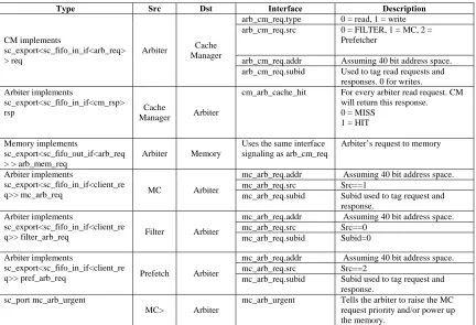
Table 3: Arbiter Interfaces
Type Src Dst Interface Description
CM implements
sc_export<sc_fifo_in_if<arb_req> > req
Arbiter Cache Manager
arb_cm_req.type 0 = read, 1 = write arb_cm_req.src 0 = FILTER, 1 = MC, 2 =
Prefetcher
arb_cm_req.addr Assuming 40 bit address space. arb_cm_req.subid Used to tag read requests and
responses. 0 for writes. Arbiter implements
sc_export<sc_fifo_in_if<cm_rsp>
rsp Cache
Manager Arbiter
cm_arb_cache_hit For every arbiter read request. CM will return this response. 0 = MISS
1 = HIT
Memory implements
sc_export<sc_fifo_out_if<arb_req > > arb_mem_req
Arbiter Memory
Uses the same interface signaling as arb_cm_req
Arbiter’s request to memory
Arbiter implements
sc_export<sc_fifo_in_if<client_re
q>> mc_arb_req MC Arbiter
mc_arb_req.addr Assuming 40 bit address space. mc_arb_req.src Src==1
mc_arb_req.subid Subid used to tag request and response.
Arbiter implements
sc_export<sc_fifo_in_if<client_re
q>> filter_arb_req Filter Arbiter
mc_arb_req.addr Assuming 40 bit address space. mc_arb_req.src Src==0
mc_arb_req.subid Subid=0
Arbiter implements
sc_export<sc_fifo_in_if<client_re
q>> pref_arb_req Prefetch Arbiter
mc_arb_req.addr Assuming 40 bit address space. mc_arb_req.src Src==2
mc_arb_req.subid Subid used to tag request and response.
sc_port mc_arb_urgent
MC> Arbiter
mc_arb_urgent Tells the arbiter to raise the MC request priority and/or power up the memory.
3.2.2. Cache Manager
39 Table 4: Cache Manager Interfaces
Type Src Dst Interface Description
PC implements
sc_export<sc_fifo_in_if<cm_req> > cm_pc_req
Cache
Manager Pixel Cache
cm_pc_req.type 00 = ALLOC. 01 = EMIT. 10 = ALLOC_EMIT. 11 = INVALIDATE
cm_pc_req.index Index in the cache to store and/or read the CM data.
cm_pc_req.subid Subid used to tag read requests and responses.
3.2.3. Pixel Cache
The following are the Pixel Cache’s interfaces to other blocks in the system.
Table 5: Pixel Cache Interfaces
Type Src Dst Interface Description
PC implements
sc_export<sc_fifo_out_if<mem_d ata> > mem_pc_data
Memory Pixel cache
mem_pc_data.data Read response data mem_pc_data.cnt Number of data transfers mem_pc_data.src Source of read request
1=MC, 2=Prefetcher mem_pc_data.subid Subid used to tag read
requests and responses. MC implements
sc_export<sc_fifo_out_if<mem_d
ata> > pc_mc_data Pixel
Cache Motion Comp.
pc_mc_data.data Read response data pc_mc_data.cnt Number of data transfers pc_mc_data.src Source of read request
1=MC, 2=Prefetcher pc_mc_data.subid Subid used to tag read
CHAPTER 4: Experimental Results
4.1.
Model Assumptions
To limit the implementation scope of the model and focus on producing data for analysis rather than building a full-fledged H.264 decoder, the following design assumptions were made.
1. Instead of capturing a read request stream from a real motion compensator, a traffic generator was built that allows the user to specify a custom macro block sequence. The user would describe the sequence one block at a time using:
a. The block upper left and lower right coordinates.
b. Indicating whether a block is a macro block for read or a sub-partition to be written by the deblocking filter.
c. The height and width of the frame.
The traffic generator will take care of generating a sequence of read and write requests as well as computing the memory addresses.
41 Figure 10: Foreman frame showing partition choices.[3]
This example frame is coded as a P slice frame with the choice of partitions overlaid on the frame. P slice frames use partitions with a single motion vector and a single reference frame. Note that the area chosen for the study has both macro blocks coded using a single 16x16 partition as well as smaller partitions around complicated area of movements like the mouth.
specify how many cycles it takes the motion compensator to consume a chunk of reference pixel data. Also, in reality, the number of neighboring pixels read when estimating a macro block depends on the motion vector received with the macro block specification. For modeling purposes, however, the number of neighboring pixels read for a macro block is dictated by a configurable parameter. Finally, the deblocking filter uses a similar
mechanism by producing a write request at a configurable frequency to try to mimic the behavior of a real filter.
3. In order to map pixel coordinates to memory address the following assumptions were made:
a. Each pixel is 16bit wide.
b. Macro blocks are traversed in 2x2 pixel regions (quads) which are stored in a contiguous 64bit block in memory.
c. Memory width is 64bit which matches the request size so request, read or write, map to a single data transfer.
Based on the above, the equation to generate the memory address of a pixel quad is:
Frame Offset +
((quad anchor Y * Frame Width) + quad anchor X) * 4 * Bytes per Pixel.
Where:
Frame offset is the start of the frame in memory. Quad anchor is the upper left pixel of the quad.
43 4. It was originally expected that this work would make use of a transaction-level model that accurately represented synchronous DRAM command latencies. Unfortunately, this model was never completed, and was considered out of the scope of this work. Therefore,the decision was made to write a simple memory model that does not implement the full DRAM functionality. This decision allowed the arbiter to be much simpler as it does not
have to implement a full-fledged memory protocol. Instead the arbiter’s implementation can focus on the ideas being presented here.
5. In order to quantify the power savings from putting the memory in self refresh mode, we used a Micron x16, 512Mb, 133 MHz, Mobile DDR device running at 1.8V. This memory has the following characteristics[18]:
P(Sref) = IDD6a × VDD = 0.3mA × 1.8V = 0.54mW
P(Std_modes) = P(PRE_PDN) + P(PRE_STDBY) + P(ACT_PDN) + P(ACT_STBY) + P(REF) + P(ACT) + P(WR) + P(RD) + P(DQ) = 89.79mW P(Average) = P(Std_modes) × %Std + P(SRef) × %SRef
Where %Std and %SRef are the percentage of time the memory is in standard mode and self refresh mode respectively. Note that the standard mode power considers a typical usage scenario as defined in [18] and uses a weighted average of the power of the various memory operations (page management, reads, writes, refresh, etc.).
6. To accurately model %SRef, we have to take into account the self refresh entry and exit latency.
a. The entry latency, defined from the arbiter’s last read/write request to memory going into self refresh, is the memory read latency plus burst length. For Micron LPSDR-166 this is 7 cycles [19].
b. The exit latency, defined from memory existing self refresh to arbiter issuing the first read/write request, is tXSR (self refresh to read command). Micron
4.2.
Memory Access Arbitration
The first chart below shows when the memory was powered down (value=1) and when it was powered up (value=0) over the time of the simulation. At the beginning of the simulation, the motion compensator asserts the mc_arb_urgent signals to reflect that its data pool is below the low watermark. This prevents the arbiter from powering down the memory until it services enough read requests from the motion compensator to get its data pool above the high watermark. At that point, the motion compensator deasserts the urgent signal allowing the arbiter to power down the memory.
While the memory is powered down, the motion compensator will be processing reference pixel data and reducing the data pool amount as can be seen in the second chart. At some point, the data pool goes below the low watermark causing the mc_arb_urgent signal to assert at which point the arbiter will power up memory and service enough read requests to reduce the urgency of the motion compensator. This cycle will be repeated throughout the simulation.
Note the asymmetry between power up and power down periods which is due to the difference between the motion compensator processing rate and the memory rate. This characteristic is typical of H.264 decoders and is the premise of the Memory Access Arbitration scheme. Power up memory for short period of times and run it at maximum bandwidth to allow for longer power down periods.
45 service the additional requests. This would result in a net power reduction due to higher power down to power up ratio as well as less power transitions.
Finally, the fourth chart shows the filter write data pool size over the simulation time. Note that the filter works out of phase with the motion compensator as it waits for a whole block to
be estimated before using frame n-1 reference pixel before it generates frame n reference pixels. The filter write data pool will start empty and builds up because memory is powered down and the arbiter is not draining. At some point, the pool exceeds the high watermark causing the filter_mc_urgent signal to be asserted at which point the arbiter will power up memory and drain the pool. The key thing here is that with the right pool sizes, we can have the motion compensator and the filter go urgent and power up memory around the same time. That way when memory is power down, the motion compensator pool is close to full and filter pool is close to empty. The opposite would be true when we power up where the motion compensator pool would be almost empty and the filter pool almost full.
For the block sequence in question, the memory is put in self refresh 1,269,376 cycles out of 1,415,320 cycles the simulation was run. This sets %Sref to 89.69% and %Std to 10.31%. The average power is:
89.79mW x 10.31% + 0.54mW x 89.69% = 9.74mW
Figure 11: Memory Access Arbitration Results 0 0.2 0.4 0.6 0.81 1.2
100000 100500 101000 101500 102000 102500 103000 103500 104000 104500 105000
1=Pwrdn,
0=Pwrup
Simulation Cycles
Memory
Self
Refresh
‐20 0 20 40
8000 9000 10000 11000 12000 13000 14000 15000 16000
Simulation Cycles
MC
Data
Pool
28 30 32 34
8000 9000 10000 11000 12000 13000 14000 15000 16000
Simulation Cycles
Number
of
Outstanding
MC
Read
Requests
0 10 20 30
8000 9000 10000 11000 12000 13000 14000 15000 16000
Simulation Cycles
47
4.3.
Reference Data Scheduling
The chart below shows the fraction of the motion compensator memory reads that hit in the cache (blue) as opposed to the ones going to memory (red) for various cache sizes. As expected, increasing the number of entries in the direct mapped cache reduces the number of evictions and allows the motion compensator to hit in the cache when it goes back in raster order and revisits a partition that is neighboring an already processed partition.
Figure 12: Motion Compensator Hits/Misses in the Cache vs. Cache size
The graph below shows the motion compensator hit rate as a percentage of total memory reads for various cache sizes. As expected, the benefit of increasing the cache size will flatten out as the number of misses approach the size of the frame. As stated earlier, the best we can do here is read every reference pixel once.
7000 7200 7400 7600 7800 8000 8200 8400 8600
64 128 256 512 768 1024
Total
MC
Memory
Reads
Number of Cache Entries
MC Misses
Figure 13: Motion Compensator hit rate in the Cache vs. Cache Size.
The graph below shows the percentage of system power saved as a function of cache size. The graph was derived from data presented in section 1.2 where we can see that 75% of memory
accesses come from the motion compensator and 20% of the system power is spent in off chip memory. Assuming that a reduction in memory accesses corresponds to a proportional reduction in memory power, then we can translate the motion compensator hit rate of H into power savings as follows.
Off chip memory savings = H * 75%
System savings = Off chip memory savings * 20% = H * 75% * 20% = H * 15%
89.00% 90.00% 91.00% 92.00% 93.00% 94.00% 95.00% 96.00% 97.00% 98.00%
0 200 400 600 800 1000 1200
Hit
Rate
49 Figure 14: System Power Reduction vs. Cache Size
The graph below shows the cache area for the various sizes chosen for the study. This data was
derived using TSMC 28nm process. According to [26], the area per bit for a 28nm SRAM is 0.127um2. With every cache entry requiring 512 bit of data storage and 26 bit of address tag storage, we can derive the total cache size. Note that we are assuming 20% overhead for SRAM read and write decoding logic.
13.40% 13.60% 13.80% 14.00% 14.20% 14.40% 14.60%
0 200 400 600 800 1000 1200
System
Power
Reduction
Figure 15: Cache Cost vs. Size
The graph below shows the increase in the area of a typical H.264 decoder when a pixel cache
is integrated into the design. The reference decoder being considered is described in [27] and takes up 5.9mm2 in 28nm process. Note that the design in [27] includes a pixel cache, but the size is not reported. The graph shows that the pixel cache is small compared to the total size of the decoder, and that adding a pixel cache is an economical way to reduce the off-chip memory portion of the H.264 decoder overall power.
0 10000 20000 30000 40000 50000 60000 70000 80000 90000
0 200 400 600 800 1000 1200
Cache
Size
(um2)
51 Figure 16: System Cost vs. Cache Size
The bar chart below shows how the motion compensator hit to miss ratio changes when the prefetcher is turned on with a 512 entries cache.
Figure 17: Motion Compensator Hits in the Cache
0.00% 0.20% 0.40% 0.60% 0.80% 1.00% 1.20% 1.40%
0 200 400 600 800 1000 1200
System Area Incr ea se
Number of Cache Entries
7700 7800 7900 8000 8100 8200 8300 8400 8500 8600 8700
Prefetcher off Prefetcher
throttled
Prefetcher non‐
throttled Number of Reads
Prefetch reads
MC Misses
When the prefetcher is turned off, the motion compensator reads hit 96.13% in the pixel cache. These hits are due to data reuse where reference pixels are kept around to be reused by the interpolator filter in the motion compensator. The fact that we are reusing reference pixels across macro blocks boundary helps quite a bit.
When the prefetcher is turned on and is not being throttled, the motion compensator hit rate goes up to 99.08% at the expense of 2.92% extra reads issued to memory.
We also looked at an intermediate usage case where the prefetcher is turned on but is throttled to only issue one read request every 16 cycles. The hit rate was pretty much unchanged but the number of extra prefetcher memory reads went down to 2.47%. This suggests that throttling the prefetcher might be a good compromise between motion compensator hit rate and memory power.
53
CHAPTER 6: Conclusion
In this work we proved that Memory Access Arbitration and Reference Data Scheduling can considerably reduce off-chip memory power. This was done by simulating these two techniques using a SystemC cycle accurate model and input stimulus that mimics real H.264 traffic.
Memory Access Arbitration implemented by the memory arbiter allows memory to be accessed in bursts with idle periods in between where memory is put in self refresh mode. It also reduces memory bus inefficiency due to read to write and write to read turnaround.
Reference Data Scheduling reduces the motion compensator memory read requests by keeping reference pixels in an on chip pixel cache to be reused by the interpolation logic. An added prefetcher helps in reducing the motion compensation read latency by increasing its hit rate in the pixel cache. That in turn reduces the motion compensator power as it eliminate pipeline stalls and allows it to be more power efficient (race to sleep).
REFERENCES
[1] T.Wiegand, G.J Sullivan, G.Bjntegarrd and A. Luthra, “Overview of the H.264/AVC video coding standard”, IEEE Trans. On Circuits Syst Video Technol., vol.13, no.7 pp.560-576, July 2003.
[2] J. Ostermann, J.Bormans, P.List, D. Marpe, M. Narroschke, F. Pereira, T. Stockhammer, and T.Weidi, “Video coding with H.264/AVC: tools, performance, and complexity”, IEEE Mag. On Circuits and Syst., vol.4, pp.7-28, First quarter 2004.
[3] Iain E.G.Richardson, “H.264 and MPEG-4 video compression”, John Willey & Sons, September 2003 , ISBN 0-470-84837-5
[4] J.Lainema and M.Karczewicz, “TML 8.4 Loop Filter Analysis,” ITU-T SG16 Doc. VCEG-N29,2001
[5] T. Lin, T. Liu and C. Lee, “A Low-Power H.264/AVC Decoder”, IEEE VLSI-TSA International Symposium, April 2005 pp.283-286
[6] M. Horowitz, A .Joch, F. Kossentini, A. Hallapuro, “H.264/AVC baseline profile decoder complexity analysis”, IEEE Transactions on Circuits and Systems for Video Technology, vol. 13, pp.704-716, July 2003.
[7] R. Wang, M. Li, J. Li, Y.Zhang, “High Throughput and Low Memory Access Sub-pixel Interpolation Architecture for H.264/AVC HDTV Decoder”, IEEE Transactions on Consumer Electronics, vol. 51, No. 3, August 2005.
[8] Adrian Wise, Rob Whitton and Yazid, “Model for estimating prediction bandwidth for H.26L”, JVT-E093, 2002..
[9] Hansoo Kim and In-Cheol Park, “High-Performance and Low-Power Memory-Interface Architecture for Video Processing Application”, IEEE Transactions on Circuits and Systems for Video Technology, vol. 11, pp.1160-1170, Nov. 2001.
[10] Marco Winzker, Peter Pirsh and Jochen Reimers, “Architecture and Memory Requirements for stand-alone and hierarchical MPEG-HDTV-Decoders with Synchronous DRAMs”, ISCAS’95 IEEE International Sym. pp.609-612, May 1995.
55
[12] Joint Video Team (JVT) of ISO/IEC MPEG and ITU-T VCEG, “Draft ITU-T recommendation and final draft international standard of joint video specification (ITU-T Rec. H.264/ISO/IEC 14 496-10 AVC”, JVTG050, 2003.
[13] Ronggang Wang, Mo Li, Jintao Li, “High Throughput and Low Memory Access Sub-pixel Interpolation Architecture for H.264/AVC HDTV Decoder”, IEEE Transactions on
Consumer Electronics, vol 51. No. 3, August 2005
[14] Yu Li, Yanmei Qu, Yun He, “Memory Cache Based Motion Compensation Architecture for HDTV H.264/AVC Decoder”, IEEE Int. Symposium on Circuits and Systems, 2007, p.2906-2909.
[15] Bruno Zatt, Altamiro Susin, Sergio Bampi, Luciano Agostini, “HP422-MoCHA: AH.264/AVC High Profile Motion Compensation Architecture for HDTV”, Circuits and Systems, 2008. ISCAS 2008. IEEE Int. Symposium on Circuits and Systems,. Issue 18-21 May 2008, p.25-28.
[16] Iain E.G.Richardson, “The H.264 Advanced Video Compression Standard”, John Willey & Sons, 2003 , ISBN 978-0-470-51692-8
[17] Gary J. Sullivan, Jens-Rainer Ohm, Woo-Jin Han, and Thomas Wiegand, “Overview of the High Efficiency Video Coding (HEVC) Standard”IEEE Transactions on Circuts and Systems for Video Technology, vol 22, NO. 12, December 2012.
[18] Micron Technical Note TN-46-12, “Mobile DRAM Power-Saving Features/Calculations”, May 2009
[19] Micron Data Sheet, “Mobile LPSDR SDRAM”, March 2011
[20] Chih-Da Chien, Ho-Chun Chen, Lin-Chieh Huang, and Jiun-In Guo, “A Low-power Motion Compensation IP Core Design for MPEG-1/2/4 Video Decoding” . IEEE International Symposium Circuits and Systems, May 2005
[22] Sheng-Zen Wang , Ting-An Lin , Liu, Tsu-Ming , Chen-Yi Lee, “A New Motion Compensation Design For H.264/AVC Decoder”, IEEE International Symposium Circuits and Systems, May 2005
[23] Vcodex, www.vcodex.com
[24] Guide to SystemC, www.doulos.com/knowhow/systemc
[25] Tsu-Ming Liu, Ting-An Lin, Sheng-Zen Wang, Wen-Ping Lee, Jiun-Yan Yang, Kang-Cheng Hou, and Chen-Yi Lee, “A 125 uW, Fully Scalable MPEG-2 and H.264/AVC Video Decoder for Mobile Applications” IEEE Journal of Solid-State Circuits, vol. 42, no.. 1, January 2007
[26] Mark LaPedus, “TSMC devises SRAM cell at 28-nm” EE Times, June 17, 2009
![Figure 3: H.264 Decoder [3]](https://thumb-us.123doks.com/thumbv2/123dok_us/1553707.1190736/12.612.116.497.82.313/figure-h-decoder.webp)
![Figure 4: Power profile of H.264 system [5]](https://thumb-us.123doks.com/thumbv2/123dok_us/1553707.1190736/14.612.222.434.212.374/figure-power-profile-of-h-system.webp)
![Figure 5: Full pixel samples (shaded and with upper case letters) and sub-pixel sample positions (unshaded with lower case letters) for quarter sample luma interpolation [12]](https://thumb-us.123doks.com/thumbv2/123dok_us/1553707.1190736/28.612.139.503.227.649/figure-samples-letters-positions-unshaded-letters-quarter-interpolation.webp)