A Dynamic Reconcile Algorithm for Address
Generator in Wimax Deinterleaver
Kavya J Mohan
1, Riboy Cheriyan
2M Tech Scholar, Dept. of Electronics and Communication, SAINTGITS College of Engineering, Kottayam, Kerala, India1 Associate Professor, Dept. of Electronics and Communication, SAINTGITS College of Engineering, Kottayam, Kerala,
India2
ABSTRACT: In this paper a new reconcile algorithm for address generator supporting varying modulation schemes in the
WiMAX deinterleaver is been put forward. WiMAX can be fixed or mobile, and uses forward error correction along with interleaving and deinterleaving techniques for combatting the transmissions errors. Interleaving and deinterleaving are inverse operations with varying complexity, with deinterleaving having upper hand. The address generator for the WiMAX deinterleaver supports QPSK, 16-QAM and 64-QAM modulation schemes in a dynamic manner thus making address generator circuitry in the deinterleaver complex and resource inefficient. In this paper the mobile WiMAX system which uses the deinterleaving system with a new high speed resource efficient algorithm for address generator is been proposed. The new algorithm for address generator is modelled using VHDL and FPGA parameter analysis are carried out with recent literatures.
KEYWORDS: WiMAX (Worldwide interoperability for microwave access), forward error correction, deinterleaving, address generator, broadband wireless access (BWA), WiFi (Wireless Fidelity).
I. INTRODUCTION
Nowadays the prevailing broadband wireless access systems are reaching their maximal performance and new broadband wireless systems such as WiMAX or 4G (Fourth generation), WiBro, 3GPP etc. are conceived to uplift the performance barriers set by the older technologies. The WiMAX can be fixed or mobile based upon the location of base station and subscriber station. In mobile WiMAX system the base station is mobile and the subscriber station can be fixed or mobile, it can support more than thousands of users in line of sight or non-line of sight scenario within a range of 30-50 km and can offer a data rate of 50-70 Mbps. For the wireless communication systems to be efficient transmitter must send the information without much overhead to receiver side, it can be possible only if the transmission is error free and reliable. For error free transmission the transmitter must use forward error correction methods to detect and correct errors without the need for re-transmission.
The transmission errors mainly occurs due to co-channel interference, noise, fading etc. and can be random errors or burst errors respectively. The random errors can be detected and corrected by using the inherent forward error correction (FEC) techniques but the burst errors are difficult to combat using the common FEC methods. For detecting and correcting burst errors interleaving techniques can be used, when we use interleaving techniques in transmitter side, deinterleaver must be used in the receiver side to perform the reverse operation. Interleaving and deinterleaving are contrary to each other and it is a two-step process which is explained in section 2.
WiMAX performs its operation based upon the IEEE standard specified in [1] which pronounces the code rates, interleaver depths within the specified modulation schemes. WiMAX can be regarded as a replacement for the existing last mile wired network, it can create an ad hoc communication network which can be deployed for disaster affected areas with ease [2]. Deinterleaver performs its operation based on the addresses which are generated from the address generator unit based upon the QPSK, 16-QAM or the 64-QAM modulation schemes respectively. Overall performance of deinterleaver depends upon the address generator unit’s performance, thus to enhance the performance of the deinterleaver unit the address generator has to optimized and made simpler and faster. In this paper a new algorithm for the address generator is been proposed based upon a correlation and the algorithm supports varying modulation schemes in the WiMAX deinterleaver, the algorithm has been found to more resource efficient in comparison to recent works [5], [9].
This paper is divided into four sections the first section deals with introduction, second section deals with the technical details of the proposed new algorithm, third section deals with the simulated waveforms and FPGA constraints are studied and the fourth section concludes this paper with a proposal to a future work.
II. TECHNICAL DETAILS FOR THE PROPOSED DESIGN
A. Necessity of deinterleaver in WiMAX
The deinterleaver is used in the receiver side of the WiMAX system which is shown in fig 2.1. In the transmitter side source produces the information bits which are then sent to the FEC encoder which produces the encoded bits, the encoded bits are to be produced in same rate as the source produces the bits.
Fig.2.1. WiMAX transreciver block diagram
Interleaver is used to assist the FEC encoder sub block. The interleaver does the interleaving of the encoded bits so as to make the encoded bits resistant to both random and burst errors respectively. The mapper does the mapping of encoded bits into corresponding symbols based upon QPSK, 16-QAM or 64 QAM techniques then it is send to the receiver via channel [7].
B. Proposed Design
In the proposed algorithm deinterleaving takes place based upon the two permutations which are stated as equations (1) and (2) respectively in [9].
(1)
(2)
In equations (1) and (2) interelaver depth is denoted by Ncbps, the number of columns by j, the number of row by d=16 for
WiMAX and parameter s=Ncpc/2 where Ncpc is the number of coded bits per sub carrier which takes the value 1, 2 or 3 for
QPSK, 16-QAM or 64-QAM respectively, denotes the floor function, which makes the direct hardware implementations complicated thus deterring the performance of the address generator in the deinterleaver. Equation (2) produces the deinterleaver addresses, which has to be produced by the address generator unit. The IEEE standard specifies the various code rates, modulation schemes and the respective interleaver depths are shown in table 1.
Table.1. Permitted Interleaver/Deinterleaver Depth in IEEE 802.16e
Table.2. Deinterleaver addresses for varying modulation techniques
Interleaver depth (Ncbps)
Modulation Schemes with allowed code rate
QPSK 16-QAM 64-QAM
1/2 3/4 1/2 3/4 1/2 2/3 3/4
96 144 192 288 288 384 432
192 288 384 576 576 - -
288 432 576 - - - -
384 576
480 - - - -
576 - - - -
Modulation type Deinterleaver address
QPSK scheme
0 16 32 48 64 80
1 17 33 49 65 81
2 18 34 50 66 82
3 19 35 51 67 83
16-QAM scheme
0 16 32 48 64 80
17 1 49 33 81 65
2 18 34 50 66 82
19 3 51 35 83 67
64-QAM scheme
0 16 32 48 64 80
17 33 1 65 81 49
34 2 18 82 50 66
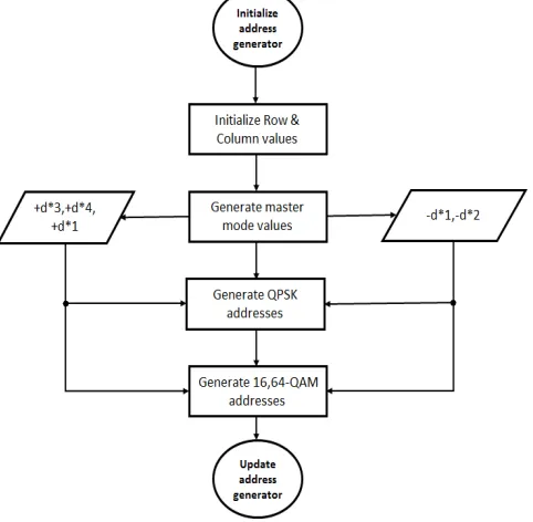
Table 2 shows the four rows and six columns deinterleaver addresses which are obtained from MATLAB after processing equations (1) and (2). Number of rows and columns varies in accordance to code rates and modulation schemes as depicted in table 1. Equations (1) and (2) cannot be effectively implemented in FPGA due to the presence of floor function. The existing methods for implementing it in FPGA uses LUT (look-up-table) approach [5] and a pattern matching approach [9] but our new correlation based approach shows better performance than these methods and the FPGA performance analysis is explained in section 3. The design is modelled in VHDL and simulated using ModelSim 6.2b software and Xilinx 14.6 was used to extract the FPGA constraints. The new algorithm is depicted using a flowchart which is shown in fig 2.2 and according to the proposed algorithm hardware replicas are designed and developed for modelling the design in HDL.
Fig. 2.2. Flowchart for the proposed new algorithm
Using the flowchart, system generates deinterleaver addresses. The algorithm works under the influence of a FSM controller (shown as the master mode state in fig 2.3) which produces the master mode values and its corresponding control signals and reset values. The FSM takes the row and column values and process it using the predefined algorithm. Based upon the modulation scheme in which the WiMAX system is working the algorithm dynamically produces the addresses. For synthesizing the algorithm, master mode value generation is carried out by hardware models which are shown in fig 2.3 and fig 2.4 respectively.
New algorithm was able to produce the addresses as stated in table 2 and the addresses were verified using MATLAB. The row and column values are given based upon the code rates and the interleaver depths which are specified in table 1 [7], [10]. The random row and column values are fed to the hardware rendering to the code rates selection and which is easily carried out by using a multiplexer or a selector. The arithmetic units which are used for developing the hardware models are in built units of Xilinx 14.6 tool.
(a) (b)
Fig.2.4. (a) The 16-QAM hardware models for the new algorithm. (b) The 64-QAM hardware models for the new algorithm
The FSM controller produces the master mode values and conferring to these values the selector selects the correlation values and then these values are transformed into corresponding deinterleaver addresses using the new algorithm. The hardware models have different row and column initial values and selector values.
Fig 2.5 shows the top-level model for the proposed design. The FSM controller gets initialized agreeing to the address generator parameters and then based upon algorithm the FSM control signals are produced.
III. EXPERIMENTAL RESULTS AND DISCUSSIONS
A. Simulated Waveforms
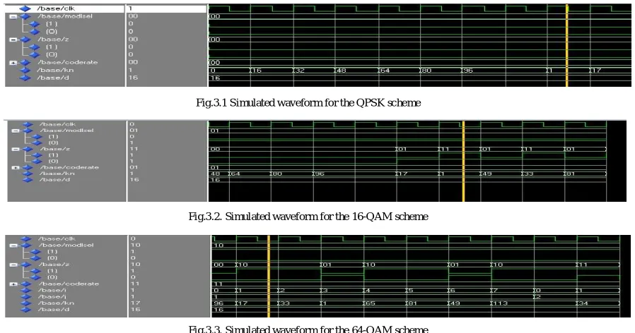
Fig 3.1 to fig 3.3 shows the simulated waveforms of the proposed work, the code rates were selected using the signal coderate, and the modulation scheme were selected using modlsel signal. The deinterleaver addresses are generated and is shown on the waveform by signal kn. The design was modelled using VHDL and simulated using ModelSim 6.2b software tool.
Fig.3.1 Simulated waveform for the QPSK scheme
Fig.3.2. Simulated waveform for the 16-QAM scheme
Fig.3.3. Simulated waveform for the 64-QAM scheme
The values after the cursor in fig.3.1, fig.3.2 and fig.3.3. Shows the deinterleaver addresses of the second row for the QPSK, 16-QAM and 64-QAM modulation schemes respectively.
B. FPGA constraints
The hardware models shown in fig 2.3 to fig 2.5 were modelled in VHDL and was synthesized in Xilinx 14.6 ISE and was compared with recent works, and the results are shown below.
FPGA parameters Performance of pattern
matching method [9]
Performance of LUT method [5]
Performance of proposed new algorithm
Slices
3.46%
17.661.33%
Flip Flops
0.50%
0.780.10%
4 input LUTs
3.35%
17.151.05%
Clock Frequency
121.820 MHz
62.51 MHz137.328 MHz
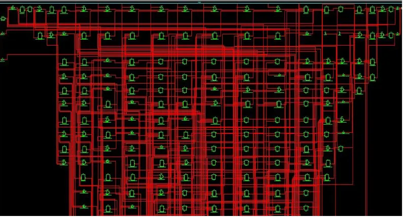
Fig.3.4. Technology schematic of the new algorithm in Spartan 3E device
Fig.3.5. FPGA performance analysis
IV. CONCLUSION
The IEEE 802.16e or the mobile WiMAX is going to be a great assurance for the upcoming wireless broadband systems in terms of performance and in future will replace the existing last mile or wired networks. The WiMAX must provide reliable transmissions which is accomplished by using interleaver in conjunction with the forward error correction encoder blocks, the receiver uses deinterleaver with address generator unit which hampers the performance of the system. In this paper a new high performance algorithm for address generator is been proposed and was modelled in VHDL and FPGA constraints were studied and compared with recent works, the proposed work has outclassed the existing works in terms of FPGA constraints. In future this algorithm can be expanded to WiFi system by considering the security protocol of both WiMAX and WiFi systems.
REFERENCES
[1] IEEE Standard for Local and Metropolitan Area Networks—Part 16: Air Interface for Fixed Broadband Wireless Access Systems—Amendment 2, IEEE Std. 802.16e-2005, 2005
[2] Jochen Schiller, “Mobile Communications”2nd ed.pearson prentice hall,2011.
[3] W. Konhauser, “Broadband wireless access solutions—Progressive challenges and potential value of next generation,” Wireless Pers. Communication, vol. 37, no. 3/4, pp. 243–259, May 2006.
[4] B. Li, Y. Qin, C. P. Low, and C. L. Gwee, “A survey on mobile WiMAX,” IEEE Commun. Mag., vol. 45, no. 12, pp. 70–75, Dec. 2007.
[5] A. A. Khater, M. M. Khairy, and S. E.-D. Habib, “Efficient FPGA imple-mentation for the IEEE 802.16e interleaver,” inProc. Int. Conf. Micro-electron., Marrakech, Morocco, 2009, pp. 181–184
[6] I. Kuon and J. Rose, “Measuring the gap between FPGAs and ASICs,”in Proc. Int. Symp. Field Programm. Gate Arrays, Monterey, CA, USA, 2006, pp. 21–30.
[7] Local and Metropolitan Networks—Part 16: Air Interface for Fixed Broadband Wireless Access Systems, IEEE Std. 802.16-2004, 2004
[8] J. G. Andrews, A. Ghosh, and R. Muhamed, Fundamentals of WiMAX: Understanding Broadband Wireless Networking. Upper Saddle River, NJ, USA: Prentice-Hall, 2007, ch. 8
[9] B. K. Upadhyaya and S. K. Sanyal,” Efficient FPGA Implementation of Address Generator for WiMAX Deinterleaver,” IEEE Trans. Circuits Syst. II, 2013, pp. 492-496