ISSN (Online) : 2319 - 8753
ISSN (Print) : 2347 - 6710
I
nternationalJ
ournal ofI
nnovativeR
esearch inS
cience,E
ngineering andT
echnologyAn ISO 3297: 2007 Certified Organization, Volume 2, Special Issue 1, December 2013
Proceedings of International Conference on Energy and Environment-2013 (ICEE 2013)
On 12th to 14th December Organized by
Department of Civil Engineering and Mechanical Engineering of Rajiv Gandhi Institute of Technology, Kottayam, Kerala, India
RAREFACTION EFFECT ON FLUID FLOW THROUGH
MICROCHANNEL
Sunildutt
M.G University Kottayam, Kerala, 686008 India
ABSTRACT
Micro-fluidics is an area of science and engineering in which the behavior of fluid is different from the predictions of the conventional flow theory. If the hydrodynamic diameter of a channel is comparable with the mean free path of the gas molecules moving inside the channel, the fluid can no longer be considered to be in thermodynamic equilibrium and rarefaction effects can occur. To avoid enormous complexity and extensive numerical cost encountered in modeling of nonlinear Boltzmann equations, the Navier-Stokes equations can be solved considering the concepts of slip flow regime and applying slip velocity boundary conditions at the solid walls. This paper presents the simulation of the laminar incompressible fluid flow through micro-channel over the slip flow regime and the appropriate boundary condition is implemented by means of a user defined function routine into finite volume solver Fluent. Three different Knudsen numbers have used to investigate the effects of rarefaction.
NOMENCLATURE
h Characteristic Length, m f Friction Factor Kn Knudsen Number
Po Poiseuille Number Re Reynolds Number λ Mean Free Path, m
µ Dynamic viscosity, Pa-s
ρ Density,
Slip Velocity, m/s
σ Tangential Momentum Accommodation Coefficient T Fluid Temperature, K
U Fluid Velocity, m/s
1.INTRODUCTION
Microfluidics is the science and technology involved in liquid transport, separation, mixing and analysis, for micro-volumes of fluids. It find applications in biochemical reaction chambers, infrared detectors, heat-exchangers and so on. The advantages are simplicity in operation, miniaturization and low costs. The rarefaction is an important parameter in gas flows through microchannels, which can take place at low-pressure gas flows in ordinary channel or in microchannel with normal pressures. Rarefaction occurs when the channel dimension becomes comparable to the mean free path of the fluid molecules and slip flow is the regime of slight rarefaction. Knudsen number is a measure of the degree of rarefaction which is defined as the ratio of mean free path to the characteristic length scale of the system. Knudsen number lies between 0.001 - 0.1 constitutes the slip flow regime. At micro level, the surface effect became more important than volume effects and chemical affinity between wall and gas affect the flow
characteristics. The slip flow can’t be directly solved using the solver Fluent 6.3, so a User defined
function written in C-source code is activated in the solver for implementing slip boundary condition. In most macro-scale applications, the fluid flow in channels is in turbulent flow regime but in micro-scale and nano-scale applications, most fluid flows are in laminar regime. In microchannels even though the fluid density would not rely on low-density regime, but because of the value of length scale which would be in order of mean free path, it could be in slip flow regime.
2. MAXWELL’S SLIP FLOW MODEL
The classical description of the velocity slip in rarefield gases flowing over a solid surface is the
Maxwell slip boundary condition. The mathematical descriptions in Maxwell’s model are derived from
the observed behavior of physical systems rather than from theoretical knowledge. The Maxwell model is used for both simple and complex flow configurations and no accuracy losses occur when converting kinetic theory dependent models to three dimensional, non-isothermal and compressible flows. So
Maxwell’s model is the widely used and accepted model. Maxwell suggested tangential slip velocity
based on the kinetic theory of gases. It is assumed that a percentage of the wall collisions were specular where as a remained percentage were diffuse. Such an assumption allows an exchange of momentum between the gas and the wall. The Tangential Momentum Accomodation Coefficient is defined as the fraction of transfer of momentum from the incident molecules to the gas molecules reflected from the wall. As slip increases, Knudsen number increases, the pressure gradient and velocity maximum diminishes. Since slip velocity allows the fluid near the walls to keep part of its momentum, the pressure gradient decreases and in order to conserve the mass flow rate the maximum velocity occurs in the core region decreases with increasing Knudsen number.
3. SLIP FLOW THEORY
Maxwell’s model assumes that in a rarefied gas flow parallel to a wall, molecules approaching the
wall will do so with an equilibrium velocity distribution, such as elsewhere in the bulk flow. On colliding with the wall, gas molecules are said to be reflected either specularly or diffusely, with the proportion of each determined by the tangential momentum accommodation coefficient. Both specularly and diffusively reflected molecules are initially incident to the wall with the same equilibrium velocity distribution. Due to the collisions at the interface, the diffusely reflected molecules will have exerted a tangential stress on the wall, and the specularly reflected molecules will not. Thus, the post wall-collision velocity distributions of the specularly and diffusely reflected molecules cannot be the same, implying that the composite stream of all the receding molecules has a non-equilibrium velocity distribution. The fluid approaching the wall from the bulk flow is assumed to be composed of molecules with an equilibrium velocity distribution.The stream of molecules receding from the wall is assumed at the microscopic level to be equivalent to a simple effusive flow. The number of molecules leaving the surface is multiplied by the velocity of the gas at the wall, the unknown slip velocity to produce the receding streams contribution
Poiseuille number is a factor for friction measurements, defined as the product of friction factor and local Reynolds number. The equation used for determining Poiseuille number is given as
where dP/dx denotes the average pressure gradient, the pressure drop occurs along the channel. Joe A. Rached et al. [1] numerically investigated the effects of Knudsen number on the velocity and temperature fields for the microchannel flow. A control- volume based numerical method is used to solve the Navier-Stokes and energy equations with slip velocity and temperature jump conditions at the walls.
Morini et al. [2] theoretically investigated the conditions for experimentally evidencing rarefaction effects on the pressure drop. It was demonstrated that for a fixed geometry of the microchannel cross -section, it is possible to calculate the minimum value of the Knudsen number for which the rarefaction effects can be observed experimentally. Three-dimensional numerical analysis for fully developed incompressible fluid flow and heat transfer through triangular microchannels over the slip flow regime was carried by Mostafa Shojaeian et al. [3]. The influences of Knudsen number, aspect ratio and Reynolds number on the fluid flow and heat transfer characteristics are extensively investigated. Webb [4] introduced microchannels as next generation devices for electronic cooling. The heat flux in these cases can reach to 100 W per sq.cm. Hettiarachchi et al.[5] numerically studied three dimensional laminar slip-flow and heat transfer in rectangular microchannels having constant temperature walls using the finite-volume method for thermally and simultaneously developing flows. They defined a modified convection-diffusion coefficient at the wall-fluid interface to incorporate the temperature-jump boundary condition.
Zhang et al.[6] established a numerical model for three-dimensional compressible gaseous slip flow in microchannel. They studied the influences of gas compressibility, rarefaction effect and size effect on fluid flow characteristics and found that the accuracy of the result is improved by modifying the gas viscosity. Ji et al. [7] studied the influence of roughness in slip flow regime with first order slip boundary conditions. They simulated the roughness with rectangular elements on two parallel plates with different spacing and heights to investigate the effect of wall roughness on friction factor and found that the effect of wall roughness reduces with increasing Knudsen number.
In the present work the effect of rarefaction on fluid flow through microchannel is investigated for three different Knudsen numbers. Navier-Stokes equations with slip flow at walls can be used to describe the physical processes. Slip condition is implemented by providing Maxwell velocity slip boundary condition on the wall by using a User Defined Function.
4.GOVERNING EQUATIONS
The flow satisfies the velocity slip condition at the wall and Maxwell’s first order slip boundary
condition is provided on the wall.
5.METHODOLOGY
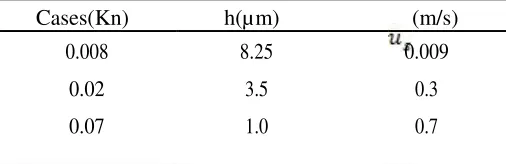
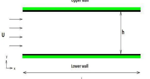
Three typical problems are studied to understand the effect of rarefaction on fluid flow characteristics. A rectangular channel is the physical domain of the problem which is viewed as two parallel plates placed one over the other. The length of the channel is 200 µm and the characteristic length is different for different Knudsen numbers. The simulation is carried out with incompressible air flowing at a free stream velocity in the positive x direction, U = 40 m/s and free stream temperature T = 300K with Mach number = 0.1. The wall temperature is set as Tw = 350K. The details are shown in TABLE 1.
TABLE 1. DETAILS AND RESULTS OF CASES Cases(Kn) h(µm) (m/s)
0.008 8.25 0.009 0.02 3.5 0.3 0.07 1.0 0.7
6.USER DEFINED FUNCTION IMPLEMENTATION
User defined function (UDF) is used for defining the boundary conditions, material properties etc. UDF is used for customization of boundary conditions, material property definitions, surface and volume reaction rate etc. The following steps involved in slip velocity routine is as follows:
· The Maxwell slip model defines the slip velocity as a function of tangential velocity gradient. These velocity gradients can be obtained using C_U_G(c, t).
· DEFINE_PROFILE macro can be used to specify the slip velocity computed from the Maxwell model at the wall.
· Get the velocity and velocity gradient at the cell centre using C_U(c,t) and C_U_G(c,t).
· Calculate the slip velocity using Maxwell slip model, close the face loop and interpret the UDF.
7.GRID INDEPENDENCE AND VALIDATION
The 2D problem geometry is created by using Gambit 2.2 software. Then the geometry is meshed into smaller cells. Boundary layer griding is provided near the channel walls so that slip occuring in the fluid-wall region can be analysed. Higher the number of cells the greater is the accuracy with more rigorous calculations and lower convergence limit. This is then exported as a 2D mesh file to be solved in solver Fluent 6.3. Fine grids have been employed over all the solid-fluid interfaces to resolve accurately the gradient of field variables. Grid independence study is conducted by using successively smaller cell sizes for the improvement of the results. To evaluate the grid size effect on the accuracy of numerical solutions, grid independence tests were performed as the grid size was refined until acceptable differences between the last two grid sizes were found. Three different grid sizes (800 × 480, 600 × 240, 400 × 120) were examined. By balancing between the computation time and accuracy, the grid size (400 × 120) is selected.
FIGURE 1. PHYSICAL DOMAIN OF PROBLEM
FIGURE 2. BOUNDARY LAYER GRID MESHING
The validation is done by modelling a rectangular channel of height 10µm and length of the channel is 200 µm. Air has been choosen as the working gas with inlet Mach number of 0.02 and inlet temperature of 300K. The wall temperature is set at 350K. A first order slip flow boundary condition is used to represent the velocity slip along the wall for Kn = 0.003 and Re = 9. The geometry is meshed in smaller cells and boundary layer griding is provided near the channel walls so that slip occuring in the fluid-wall region can be analysed. Higher the number of cells, the greater is the accuracy with more rigorous calculations and lower convergence limit. The grids are refined near the wall region to obtain highly accurate numerical solutions.
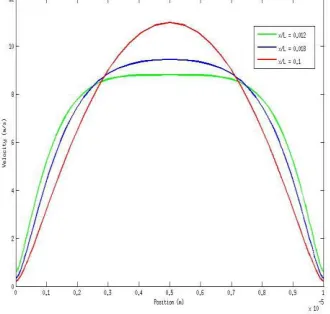
FIG 4. shows the development of fully developed velocity profile. For various values of x/L close to the inlet the maximum velocity is off centerline until a fully developed profile is established. At the wall close to the inlet ie. at x/L = 0.012, the velocity slip at the wall is largest in the domain. But as x/L increases, the hydrodynamic boundary layer increases, which causes the centerline velocity to increase and the velocity slip at the wall to decrease. At x/L = 0.018 developing velocity profile is obtained. Flow in the entrance region is called hydrodynamically developing flow since in this region where the velocity profile develops. The region beyond the entrance region in which the velocity profile is fully developed and remains unchanged is called the hydrodynamically fully developed region which is obtained at x/L = 0.1
FIGURE 3. SLIP VELOCITY ALONG MICROCHANNEL LENGTH
8. RESULTS AND DISCUSSIONS
The slip flow is modelled through a microchannel of length 200 µm with characteristic lengths 8.75 µm, 3.5 µm and 1µm respectively and the corresponding Kn numbers are 0.008, 0.02 and 0.07. The Re numbers used are 47, 19 and 5 respectively. The simulation results shows that slip velocity is a decreasing function of axial dimension and is independent of radial component of velocity. The friction factor decreases as Knudsen number increases, so the slip increases with increasing Knudsen number. Poiseuille number is significantly lower for the flow with a higher Knudsen number than that with a lower Knudsen number because the slip condition implies less shear stress against the wall and there is a reduction in friction factor. The value of the maximum velocity is always smaller in the case of higher slip flow. As the fluid slips at the wall in the slip case, the centreline velocity should decrease to conserve the mass flow rate. For Kn = 0.008 the maximum centreline velocity is about 61.1 m/s and for Kn = 0.07 the maximum centreline velocity is about 57.6 m/s.
FIGURE 5. SIMULATION OF FLUID FLOW THROUGH MICROCHANNEL FOR Kn = .008
FIGURE 6. SIMULATION OF FLUID FLOW THROUGH MICROCHANNEL FOR Kn = .02
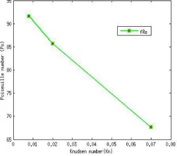
FIGURE 7. SIMULATION OF FLUID FLOW THROUGH MICROCHANNEL FOR Kn = .07 Poiseuille number is determined by plotting a graph for pressure gradient along the microchannel length. It is clear that higher the Knudsen number, Poiseuille number will be smaller. The lower Poiseuille number is expected since the slip condition implies less shear stress against the wall and a higher Knudsen number means larger slip.
9.CONCLUSION
The slip flow is modelled through a rectangular microchannel and the following conclusions are reached. The friction factor decreases as Knudsen number increases, so the slip velocity increases with increasing Knudsen number. But with the increase of slip velocity, the velocity maximum diminishes. Poiseuille number is significantly lower for the flow with a higher Knudsen number than that with a lower Knudsen number. So Slip effect reduces the friction in microchannel flow and fluid can be driven through it with a lesser power consumption.
REFERENCES
[1] Joe A. Rached, Nancy M. Daher, 2006. “Numerical prediction of slip flow and heat transfer in microchannels”. International Journal of
Thermal Sciences, 2(5), June, pp. 870-881
[2] Morini G.L., Lorenzini M., Spiga M., 2005. “A criterion for experimental validation of slip-flow models for incompressible rarefied gases
through microchannels”. Microfluid Nanofluid, 1, 190-196
[3] Mostafa Shojaeian, Seyed Ahmad Reza Dibaji, 2010. “Three dimensional numerical simulation of the slip flow through triangular
microchannels”.International Journal of Heat and Mass Transfer, Vol:37, August, pp.324-329
[4] Webb R. 2005. “Next generation devices for electronic cooling with heat rejection to the air”. Journal of Heat Transfer-127
[5] H.D. Madhawa, Mihajlo, William M, 2008. “Three dimensional laminar slip flow and heat transfer in a rectangular microchannel with
constant wall temperature”. International Journal of Heat and Mass Transfer, Vol:51, August, pp 5088-5096
[6] Zhang T.T., Jia L., Wang Z.C., Li C.W., 2009. “Slip flow characteristics of compressible gaseous in microchannels” Energy Conservation and Management, Vol:50, June, pp.1676-1681
[7] Yan Ji, Kun Yuan, J.N. Chung, 2006.“Numerical simulation of wall roughness on gaseous flow and heat transfer in a microchannel ” International Journal of Heat and Mass Transfer, Vol:49, July, pp. 1329-1339
[8] M. Hakak Khadem, M. Shams, and S. Hossainpour, 2009 “Effects of rarefaction and compressibility on fluid flow at slip flow regime by